Design of a Novel Ku/X-Band Reflectarray/Transmit-Array Antenna
with Frequency Selective Surface
Fei Xue1, 2, Hongjian Wang1, 2, *, Xingchao Dong1, 2, Yang Liu1, 2, and Xingwei Zhang1, 2
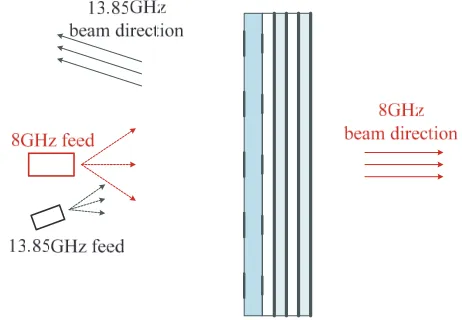
Abstract—A planar reflectarray/transmitarray antenna which reflects/transmits the incident fields radiating from feed antenna is presented. The antenna works as a reflectarray at 13.85 GHz and a transmitarray at 8 GHz. The unit cell is composed of three layers. The first layer consists of a crossed-dipole element and a square ring frequency selective surface (FSS) on the top and bottom surfaces of a dielectric substrate. The second and third layers are identical and consist of a square ring slot element on both sides of a dielectric substrate. An air gap is inserted between layers. The aperture of the antenna is 225 mm which equals 10.4 wavelengths at 13.85 GHz and 6 wavelengths at 8 GHz. The reflectarray/transmitarray antenna is fabricated, and NSI planar near-field system is used to measure the performances of the prototype. Good agreement between the simulated and measured results has been achieved. The measured gain is 27.1 dB in reflection mode at 13.85 GHz resulting in a 38% aperture efficiency and 23.1 dB in transmission mode at 8 GHz resulting in a 45.7% aperture efficiency.
1. INTRODUCTION
Long distance communication requires high gain antennas. The traditional high gain antenna mainly refers to parabolic reflector and phased array antennas. However, both of them have some drawbacks. Parabolic reflector antenna is always bulky and nonplanar. The complex feeding network of the phased array antenna restricts its application to some extent. Reflectarray antenna has emerged in recent years as another high gain antenna [1, 2]. The most important virtues of a reflectarray are its flatness, low profile, low cost and beam steering ability. The reflectarray elements illuminated by a feed antenna are designed to adjust the phase of the incident wave and form a desired phase front in the far field.
Transmitarray antenna is another kind of high gain antenna newly emerged in recent years [3, 4]. A transmitarray antenna consists of a feed antenna and a flat array with many radiating elements. Each element is used to compensate for the phase of the incident wave resulting in a focused beam on the other side of the planar array.
The frequency selective surface (FSS) has been widely used in the design of multi-band reflectarray. In [5], a dual-band, linearly polarized FSS-backed reflectarray was presented, and a double square ring element was used as the cell element of the X- and Ka-bands. A single square ring was used as the FSS element to substitute the ground plane of Ka-band. A dual-band FSS was used as the ground plane to reduce the mutual couplings between the two operating bands in [6]. The measured results of the single-layer prototype showed good radiation performance and low mutual couplings between the two bands. In [7], a two-layer FSS made by a single square ring and two pairs of dipoles at each layer is designed for Ku/Ka tri-band applications. The FSS provides a transmission range of 10.7 GHz–12.05 GHz and strong reflections around 20 GHz and 30 GHz with stable performance.
Received 18 January 2017, Accepted 25 March 2017, Scheduled 5 April 2017
* Corresponding author: Hongjian Wang ([email protected]).
1 CAS Key Laboratory of Microwave Remote Sensing, National Space Science Center, Chinese Academy of Sciences, Beijing 100190,
both in reflection mode and transmission mode. Measured results show the gain of 27.1 dB with aperture efficiency of 38% in reflection mode at 13.85 GHz and 23.1 dB with aperture efficiency of 45.7% in transmission mode at 8 GHz.
Figure 1. The configuration of the reflectarray/transmitarray antenna.
2. ELEMENT DESIGN AND PHASE CHARACTERISTICS
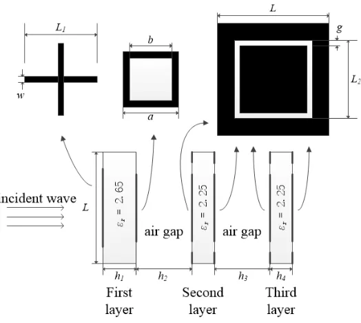
The element construction of the reflectarray/transmitarray antenna is presented in Fig. 2. The element consists of three dielectric substrate layers with εr = 2.65 for the first layer and εr = 2.25 for the
second and third layers. As shown in Fig. 2, a crossed-dipole element and a square ring element are separately printed on the two sides of the first dielectric substrate. The square ring structure is a band-stop FSS element which reflects the 13.85 GHz and transmits other bands. The second layer consists of a square ring slot element printed on both sides of the dielectric substrate. The third layer is identical to the second one. There is an air gap between layers. The lattice period of element L is set to 15 mm, which equals 0.69 wavelengths in reflection mode at 13.85 GHz and 0.4 wavelengths in transmission mode at 8 GHz. The reflection and transmission characteristics of the element are analyzed in HFSS, and master-slave boundaries with Floquet port are used to model periodic structures. The final optimized parameters are as follows: w= 0.6 mm,a= 5.6 mm, b= 3.9 mm, g = 0.75 mm, h1 = 3 mm, h2 =h3= 2 mm, h4 = 2 mm.
Figure 3 shows the reflection and transmission performance of the FSS structure. As can be seen, the square ring FSS structure reflects 13.85 GHz and transmits 8 GHz.
Figure 2. The configuration of the element.
Figure 3. Reflection and transmission coefficient of the FSS structure.
angles have little influence on reflection phase and magnitude. The reflection magnitudes of the element are greater than −0.3 dB at 13.85 GHz for different incident angles.
Figure 5 depicts the transmission phase and magnitude of the element for different incident angles at 8 GHz. Similarly, it can be seen that incidence angles have little influence on the transmission phase and magnitude of the element. The transmission magnitudes of the element are greater than −1.5 dB in most of the dimension range at 8 GHz for different incident angles, except the large angles (θ≥30◦). The mutual coupling between reflection and transmission modes is also investigated, as shown in Fig. 6. It can be concluded that transmission mode has little effect on the reflection mode and vice versa, which indicates low mutual coupling levels between the two modes.
Figure 4. Reflection phase and magnitude of the element for different incident angles at 13.85 GHz.
Figure 5. Transmission phase and magnitude of the element for different incident angles at 8 GHz.
(a) (b)
Figure 6. Effect ofmutual coupling between reflection mode and transmission mode. (a) Transmission mode on reflection mode. (b) Reflection mode on transmission mode.
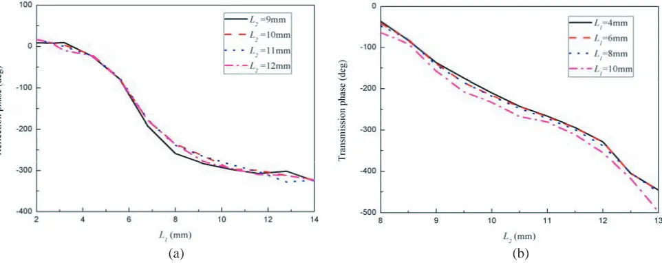
Figure 8 depicts the transmission phase and magnitude of the element at 8 GHz and 13.85 GHz. According to Fig. 8, the transmission magnitude of the element is larger than −1.6 dB at 8 GHz (transmission mode), while it is below−10 dB at 13.85 GHz (reflection mode) for the dimension range from 8.7 mm to 12.5 mm, and the transmission phase of the element is about 280◦ at 8 GHz in that range. It can be concluded from Fig. 7 and Fig. 8 that the element is a suitable choice to design a reflectarray/transmitarray antenna.
3. REFLECTARRAY DESIGN AND PERFORMANCE
Figure 7. Reflection phase and magnitude of the element at 13.85 GHz and 8 GHz.
Figure 8. Transmission phase and magnitude of the element at 8 GHz and 13.85 GHz.
(a) (b)
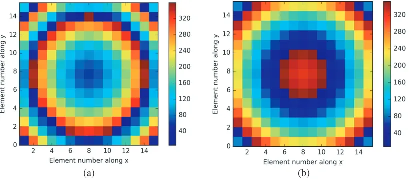
Figure 9. Phase distribution of the reflectarray/transmitarray antenna aperture. (a) Reflection mode at 13.85 GHz. (b) Transmission mode at 8 GHz.
feed blockage, and the main beam points to the mirror direction of the feed offset angle. A Ku-band pyramidal horn antenna is designed as the feed in reflection mode. The simulated gain of the feed is 15.4 dB with illumination taper at the edge of antenna aperture of about −9 dB. In transmission mode at 8 GHz, the focal distance F is 193.5 mm, which shows an F/D of 0.86. Since there is no feed blockage in transmission mode, the antenna is designed to be center-fed by an X-band pyramidal horn. The simulated gain of the feed horn is 13.6 dB with edge taper of −7.6 dB.
Figure 9 shows the designed phase distribution on the aperture of reflection mode at 13.85 GHz and transmission mode at 8 GHz. Fig. 10 shows photographs of the reflectarray/transmitarray antenna. The top and bottom surfaces of the first dielectric substrate layer are shown in Fig. 10(a). The second layer has two identical surfaces, and Fig. 10(b) shows one side of the second dielectric substrate layer. The third layer is identical to the second one. Fig. 11 shows the measurement setup for reflection and transmission modes.
Figure 10. Photographs of the designed antenna. (a) Top and bottom surface of the first dielectric layer. (b) One side of the second dielectric layer.
(a) (b)
Figure 11. Measurement setupof the antenna. (a) Reflection mode. (b) Transmission mode.
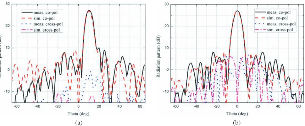
and simulated results. The measured gain is 27.1 dB at 13.85 GHz with the sidelobe levels of−17.1 dB and −19 dB for E-plane and H-plane, respectively. The measured cross-polarization level is below
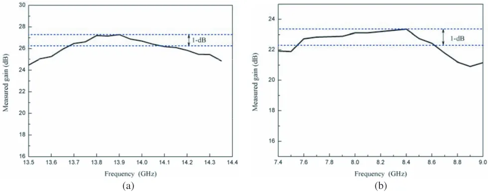
−27.8 dB and−20 dB forE-plane andH-plane, respectively. Fig. 13 depicts the measured and simulated radiation patterns of the antenna in transmission mode at 8 GHz. It can be concluded that the measured gain is 23.1 dB at 8 GHz with sidelobe levels of −16.5 dB in E-plane and −19 dB in H-plane. The measured cross-polarization levels are below−33 dB and−28.1 dB inE-plane andH-plane, respectively. Fig. 14 plots the measured gain against frequency for both reflectarray and transmitarray. It can be observed that the 1-dB gain bandwidths for the reflection and transmission modes are 3.1% and 13.5%, respectively.
The aperture efficiency ε is calculated using ε = Gm/Dideal, Dideal = 4πA/λ20, where Gm is the
(a) (b)
Figure 12. Measured and simulated radiation patterns in reflection mode at 13.85 GHz. (a) E-plane. (b)H-plane.
Figure 13. Measured and simulated radiation patterns in transmission mode at 8 GHz.
Table 1. The performance of reflectarray/transmitarray antenna.
Mode reflection transmission
Center Frequency (GHz) 13.85 8
Aperture Size (Number of wavelengths) 10.4 6
Feed Mode Offset-fed Center-fed
Measured Gain (dB) 27.1 23.1
Sidelobe level (dB) <−17.1 <−16.5 Cross-pol Level (dB) <−27.8 <−28.1
Aperture Efficiency (%) 38 45.7
(a) (b)
Figure 14. Measured gain versus frequency. (a) Reflection mode. (b) Transmission mode.
4. CONCLUSION
The design of a reflectarray/transmitarray antenna is presented. The antenna can work in reflection and transmission modes at 13.85 GHz and 8 GHz, respectively. The element is a three-layer structure. A crossed-dipole element and square ring FSS are printed on the upper and lower surfaces of the first dielectric substrate layer. The second and third layers are identical and consist of a square ring slot element on both sides of the dielectric substrate. An air gap is added between layers. A 225×225 mm2 reflectarray/transmitarray antenna prototype is fabricated and measured. Both the measured and simulated results show a good radiation performance of the antenna.
REFERENCES
1. Huang, J. and J. A. Encinar, Reflectarray Antennas, John Wiley & Sons, Institute of Electrical and Electronics Engineers, 2008.
2. Tsai, F. C. E. and M. E. Bialkowski, “Designing a 161-element Ku-band microstripreflectarray of variable size patches using an equivalent unit cell waveguide approach,” IEEE Transactions on Antennas and Propagation, Vol. 51, No. 10, 2953–2962, 2003.
3. Ryan, C. G. M., M. R. Chaharmir, J. Shaker, et al., “A wideband transmitarray using dual-resonant double square rings,”IEEE Transactions on Antennas and Propagation, Vol. 58, No. 5, 1486–1493, May 2010.
4. Rahmati, B. and H. R. Hassani, “Low-profile slot transmitarray antenna,” IEEE Transactions on Antennas and Propagation, Vol. 63, No. 1, 174–181, Jan. 2015.
5. Chaharmir, M. R., J. Shaker, and H. Legay, “Dual-band Ka/X reflectarray with broadband loop elements,” IET Microwave, Antennas &Propagation, Vol. 4, No. 2, 225–231, 2010.
6. Chen, Y., L. Chen, H. Wang, X. T. Gu, and X. W. Shi, “Dual-band crossed-dipole reflectarray with dual-band frequency selective surface,” IEEE Antennas and Wireless Propagation Letters, Vol. 12, 1157–1160, 2013.
7. Abdollahvand, M., J. A. Encinar, K. Forooraghi, Z. Atlasbaf, and J. E. Page, “Tri-band FSS for Ku/Ka bands reflector antennas,” 2016 10th European Conference on Antennas and Propagation (EuCAP), Davos, Switzerland, 2016.
9. Rahmati, B. and H. R. Hassani, “High-efficient wideband slot transmitarray antenna,” IEEE Transactions on Antennas and Propagation, Vol. 63, No. 11, 5149–5155, Nov. 2015.