A SINGLE CHIP DESIGN AND
IMPLEMENTATION OF AES -128/192/256
ENCRYPTION ALGORITHMS
L.Thulasimani *
*Lecturer, Department of Electronics and Communication Engineering PSG College of Technology, Coimbatore
and
. M.Madheswaran
Principal
Muthayammal Engineering College, Rasipuram
ABSTRACT
In this paper an efficient hardware architecture design and implementation of all candidates of AES encryption standards AES-128, AES-192 and AES-256 on the same hardware is proposed. AES algorithm proposed by NIST has been widely accepted as best cryptosystem for wireless communication security. The hardware implementation is useful in wireless security like military and mobile phones. This contribution investigates implementation of AES Encryption with regards to FPGA and VHDL.Optimized and synthesized VHDL code for AES-128, AES-192 and AES-256 for encryption of 128-bit data is implemented. Xilinx ISE 9.2i software is used for simulation. Each algorithm is tested with sample vectors provided by NIST output results are perfect with minimal delay. The proposed design consumes less power and area which is suitable battery driven mobile phones. Throughput reaches the value of 666.67 Mbps for encryption of 128- bit data with AES-128 key with FPGA device XC2V6000BF957-6. Key words: Rijindael Cipher, reconfiguration, encryption, decryption
1.INTRODUCTION:
128-bit data input and 128-128-bit data output is developed and the flow chart is shown in fig 1. In this paper the proposed work in which encryption process is explained with the flow of steps along with their algorithms which are iteratively used for encrypting and decrypting and the results along with discussions are presented.
Section 2 of the paper provides a description of the Rijndael Algorithm. Section 3 outlines the design of the proposed Rijndael implementations. Performance results are given in section 4. Finally, concluding remarks are made in section 5.
2.DESCRIPTION OF AES ALGORITHM:
Advanced Encryption Standard is the successor of Data Encryption Standard which was in use during the early 1977 to 1990. In DES encryption is based on a symmetric key algorithm that uses a 56-bit key. However by the mid 1990’s, it was clear that the DES with 56-bit is insecure for many applications since the key is very small. Then it was upgraded to Triple DES which was believed to be practically secure although there are theoretical attacks. Thus in Nov-26-2001 the FEDERAL INFORMATION PROCESSING STANDARDS PUBLICATION 197(FIPS 197) specifies an algorithm called Advanced Encryption Standard (AES). AES is based on the principle known as Substitution Permutation network (SP-network) which means there will be a series of linked mathematical operations in the block cipher algorithm.AES encrypts a data block of 128-bits which is fixed with three different key sizes 128,192,256 bits. The operations are based on Rinjdael algorithm. The input of AES algorithm is 128-bit or 16 byte data which can be specified as a block. The basic unit of processing in the AES algorithm is a byte. All byte values in the AES algorithm will be presented as the concatenation of its individual bit values (0 or 1) between the braces in the order (b7, b6, b5, b4, b3, b2, b1, b0). These bytes are interpreted as finite field elements using a polynomial representation as follows
b7X7+ b6X6+ b5X5+ b4X4+ b3X3+ b2X2+ b1X+b0 =
Internally in AES algorithm operations are performed on a two-dimensional array of bytes called the state. The state consists of four rows of bytes, each containing Nb bytes, where Nb is the block length divided by 32 (4 for 128-bit key, 6 for 192-bit key, 8 for 256-bit key). Likewise the key length and number of rounds(iterations) differ from key to key as shown in table 1.
Table1 Different keys and its attributes
Algorithm Key length (Nk words) Block Size (Nb words) Number of rounds (Nr) AES-128 4 4 10
AES-192 6 4 12 AES-256 8 4 14
AES Encryption:
Encryption is the process of converting the plain text into a format which is not easily readable and is called as cipher. The cipher is got by doing a series of mathematical operations iteratively.
a) Sub Bytes:
In this sub bytes step the data in the plain text is substituted by some pre-defined values from a substitution box. The substitution box which is used commonly is rinjdael substitution box. The substitution box is invertible.
b) Shift Rows:
In shift rows operation the rows in the 4×4 matrix is shifted to left r bits and r varies with the rows of the matrix(r=0 for row1, r=1 for row2, r=2 for row3, r=3 for row 4). This process is illustrated in fig 2.
This has the effect of moving positions of lower positions in the row, while the lowest bytes wrap around to the top of the row.
c) Mix Columns:
Mix column is calculated using the below formula.
a(x) = {2}x3 + {3}x2 + {1}x + {1}.
The mix column transformation operates on the state column by column, treating each column as a four term polynomial. The columns are considered as polynomials over GF (28) and multiplied modulo x4 + 1 with a
fixed polynomial a(x) which is got from the above formula. This can also written as a matrix multiplication s’(x) = a(x) s(x)
d) Add Round Key:
In the add round key step the 128 bit data is xored with the sub key of the current round using the key expansion operation. The add round key is used in two different places one during the start that is when round r=0 and then during the other rounds that is when 1 ≤ round≤ Nr, where Nr is the maximum number of rounds. The formula to perform the add round key is S’(x) = S(x) R(x)
where S’(x) – state after adding round key ,S(x) – state before adding round key and R(x) – round key
e) Key Expansion:
The key expansion has three steps: Byte Substitution subword(),Rotation rotword() and Xor with RCON
(round constant).The input to key schedule is the cipher key K. Key expansion generates a total of Nb(Nr + 1) words. The algorithm requires an initial set of Nb words, and each of the Nr rounds requires Nb words of key data. The resulting key schedule consists of a linear array of 4-byte words, denoted [wi ], with i in the range 0 ≤ i < Nb(Nr + 1).The subword () function takes a four byte input and applies the byte substitution operation and produces an output word. The rotword() takes a word [a0, a1, a2, a3] as input and performs a cyclic permutation to produce [a1, a2, a3, a0] as output word. The round constant word array rcon[i] is calculated using the below formula in rinjdale finite field.
rcon[i]= mod + + +x+1
The first Nk words of the expanded key are filled with the cipher key. Every following word w[i] is equal to the xor of previous word w[i-1] and the word Nk positions earlier w[i-Nk]. For words in positions that are a multiple of Nk, a transformation is applied to w[i-1] prior to the XOR, followed by an XOR with a round constant Rcon[i]. This transformation consists of a cyclic shift of the bytes in a word rotword() and byte substitution subword().
But in key expansion of 256-bit cipher if Nk=8 and i-4 is a multiple of Nk then subword () function is applied to w [i-1] prior to the xor. The algorithm for the key expansion routine is given in table 2. Thus with all the above operations the algorithm for the encryption of the data is as follows. Since it begins and ends with the add round key operation there is no wasted un keyed step in the beginning or the end. The table 3 shows the algorithm for implementation of all three AES encryption.
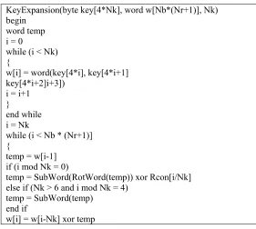
Table 2 Algorithm for key expansion
KeyExpansion(byte key[4*Nk], word w[Nb*(Nr+1)], Nk) begin
word temp i = 0
while (i < Nk) {
w[i] = word(key[4*i], key[4*i+1] key[4*i+2]i+3])
i = i+1 }
end while i = Nk
while (i < Nb * (Nr+1)] {
temp = w[i-1] if (i mod Nk = 0)
temp = SubWord(RotWord(temp)) xor Rcon[i/Nk] else if (Nk > 6 and i mod Nk = 4)
temp = SubWord(temp) end if
i = i + 1 }
end while end
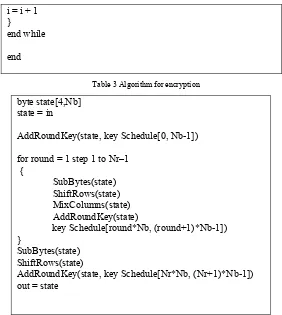
Table 3 Algorithm for encryption
byte state[4,Nb] state = in
AddRoundKey(state, key Schedule[0, Nb-1]) for round = 1 step 1 to Nr–1
{
SubBytes(state) ShiftRows(state) MixColumns(state) AddRoundKey(state)
key Schedule[round*Nb, (round+1)*Nb-1]) }
SubBytes(state) ShiftRows(state)
AddRoundKey(state, key Schedule[Nr*Nb, (Nr+1)*Nb-1]) out = state
3.HARDWARE IMPLEMENTATION OF RIJNDAEL ENCRYPTION ALGORITHM
Figure 1. Flow Chart Of AES Encryption Implementation
3.1Testing and Verification
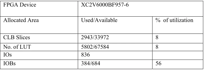
To ensure the proposed design gives a better results in terms of area and throughput the design is implemented Xilinx 9.2 and FPGA device XC2V6000BF957-6 used for downloading. In table 1. The device utilization summary of complete algorithm i.e. AES-128, AES-192, AES-256 in same hardware is shown.
Table 1. Device utilization summary of AES Encryption
The proposed design is compared with other different design implementation in Xilinx FPGA device. The proposed device is implemented in XC2V6000BF957-6 to have sufficient memory to implement the entire three different rijndael algorithms. The maximum core frequency is 62.5 MHz Each round are completed in one clock cycle and one clock cycle for registering the input, so total clock cycle need for processing 128-bit data is 12 clocks for AES-128. As a result 666.7 Mbps of throughput is achieved. Throughput calculated by other researchers is listed in table2.
FPGA Device XC2V6000BF957-6
Allocated Area Used/Available % of utilization CLB Slices 2943/33972 8
No. of LUT 5802/67584 8 IOs 836
IOBs 384/684 56
Cipher Text
Key(128/192/256) Plain Text
Key
scheduler
Round
Key 1
Round
Key 2
Round
Key n
Round
Key 1
Round
Key 2
Round
Key n
Sub Bytes
Shift rows
Mix Columns
AddRound
Key
Sub Bytes
Shift rows
AddRound
Key
Sboxx
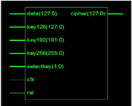
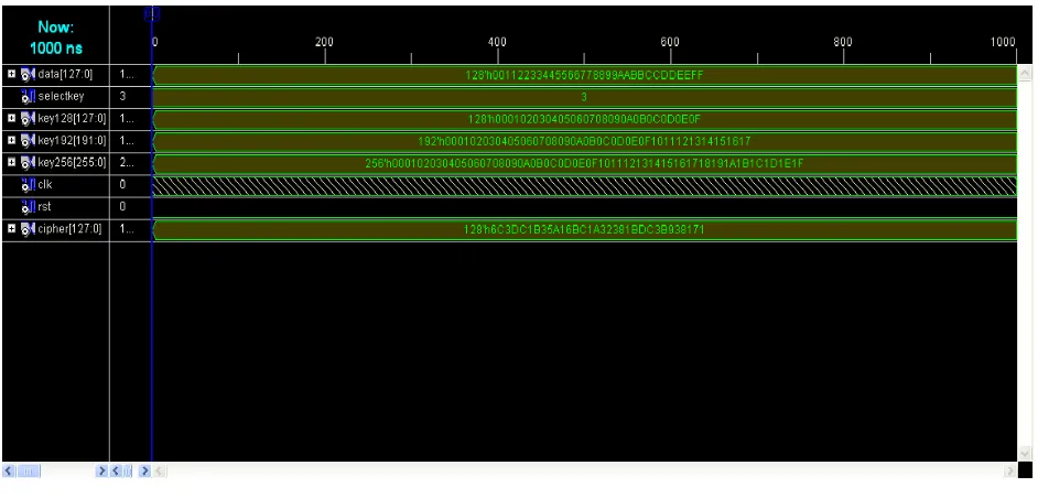
The table 2. Show s that proposed design outperforms all designs based on iterative looping in terms of area and throughput. The performance of AES-192 and AES 256 is also verified and simulation results are given. The novel architecture to implement all AES candidates in same hardware proposed is shown in figure 2. the simulation results of various AES key lengths is shown in figure 3,4 and 5.
Figure 2 schematic Diagram AES-128/192/256 Architecture
Figure 3 Simulation output of AES-128 Encryption
Design Device Area (CLBs) Throughput Mbits/Sec
Gaj XCV1000BG560-6 2902 331.5 Dandalis XCV 1000 5673 353.0 Proposed
Figure 4. Simulation output of AES-192 Encryption
Figure 5.Simulation output of AES-256 Encryption
Conclusion:
design approach in order to minimize the hardware utilization. Thus it can reduce the space by enclosing three different encryption standards in a single architecture and the power consumption can also be reduced which makes it usable in battery operated network devices having Bluetooth and wireless communication devices like software radio. Throughput reaches the value of 666.7Mbps for AES-128 encryption with FPGA device XC2V6000BF957-6.
REFERENCES
[1] J. Daemen, V.Rijmen: The Rijndael Block Cipher: AES Proposal : First AES Candidate Conference (AES1) : August 20-22, 1998 [2] A. Dandalis, V.K. Prasanna, J.D.P. Rolim: A Comparative Study of Performance of AES Candidates Using FPGAs: The Third Advanced
Encryption Standard (AES3) Candidate Conference, 13-14 April 2000, New York, USA.
[3] T. Ichikawa, T. Kasuya, M. Matsui: Hardware Evaluation of the AES Finalists: The Third Advanced Encryption Standard (AES3) Candidate Conference, 13-14 April 2000, New York, USA.
[4] K. Gaj, P. Chodowiec: Comparison of the Hardware Performance of the AES Candidates using Reconfigurable Hardware: The Third Advanced Encryption Standard (AES3) Candidate Conference, 13-14 April 2000, New York, USA.
[5] Xilinx VirtexTM-E 1.8V Field Programmable Gate Arrays: URL: http://www.xilinx.com: November 2000.
[6] A.J. Elbirt, W. Yip, B. Chetwynd, C. Paar: An FPGA Implementation and Performance Evaluation of the AES Block Cipher Candidate Algorithm Finalists: The Third Advanced Encryption Standard (AES3) Candidate Conference, 13-14 April 2000, New York, USA. [7] M.McLoone, J.V. McCanny: Apparatus for Selectably Encrypting and Decrypting Data: UK Patent Application No. 0107592.8: Filed
March 2001.
[8] B. Weeks, M. Bean, T. Rozylowicz, C. Ficke: Hardware Performance Simulations of Round 2 Advanced Encryption Standard Algorithms: The Third Advanced Encryption Standard (AES3) Candidate Conference, 13-14 April 2000, New York, USA
[9] Announcing the ADVANCED ENCRYPTION STANDARD (AES)” Federal Information Processing Standards Publication 197 November 26, 2001
[10] Dennis Ka Yau Tong, Pui Sze Lo, Kin HongLee, Philip H.W. Leong, “A System Level Implementation of Rijndael on a Memory-slot based FPGA Card”, Proceedings of the 2002IEEE International Conference on Field Programmable Technology (FPT), Hong Kong,pp. 102-109, 2002
[11] A.J. Elbert, E. Yip, B. Chetwynd, C. Paar: An FPGA Implementation and Performance Evaluation of the AES Block Cipher Candidate Algorithm Finalists, IEEE Transactions on VLSI, August 2001, vol. 9, no. 4, pp. 545-557.
[12] M. McLoone, J.V McCanny: High Performance Single-Chip FPGA Rijndael Algorithm Implementations, CHES 2001, pp. 65-76.
AUTHORS PROFILE
L. Thulasimani has obtained her BE and ME degree from Coimbatore Institute of Technology, India in 1998 and 2001 respectively. She has started her teaching profession in the year 2001 in PSNA Engineering College, Dindigul. At present she is an Lecturer in department of Electronic and Communication Engineering in PSG college of Technology, Coimbatore .She has published 4 research papers in International and National conferences. She is a part time Ph.D research scalar in Anna University Chennai. Her areas of interest are Wireless security, Networking and signal processing. She is a life member of ISTE and IEEE.