MODEL FOREBODING CONTROL OF BUCK-BOOST
DIRECT CURRENT - DIRECT CURRENT
CONVERTER FOR CONSTANT VOLTAGE
APPLICATIONS
Dr.Ravi Kumar
1, B.JohnWesley
2, P.Edukondalu
3ABSTRACT
This paper proposes a Model Predictive Control methodology for a non-inverting Buck-Boost DC-DC
converter for its efficient control. PID and MPC control strategies are simulated for the control of
Buck-Boost converter and its performance is compared using MATLAB Simulink model. MPC shows better
performance compared to PID controller. Output follows reference voltage more accurately showing that
MPC can handle the dynamics of the system efficiently. The proposed methodology can be used for constant
voltage applications. The control strategy can be implemented using a Field Programmable Gate Array
(FPGA).
Keywords : Buck-Boost DC-DC Converter, FPGA, MPC
I. INTRODUCTION
There are many control strategies available for the control of power converters. Proportional Integral and Derivative (PID) control is commonly used control methodology. The widely used linear PID control depends on the decision of the operation point that restricts the performances [1]. Model predictive control (MPC) is an advanced method of process control that has been in use in the process industries in chemical plants and oil refineries since the 1980s. It has also been used in power system balancing models during recent years. [2] Model predictive controllers rely on process dynamic models obtained by system identification; most often linear empirical models are used. The main advantage of MPC is that it allows the current timeslot to be optimized, taking into account future timeslots. A finite time-horizon is optimized, but only the current timeslot is implemented. MPC take control actions by anticipating future events. PID and LQR controllers do not have this predictive ability. MPC is a digital control.
Model Predictive control is normally used as a supervisory control strategy with the control action taking place in minutes or hours [5]. Conventional controllers like PID control is used as low level control with control action taking place in seconds. But the conventional controllers will not consider the constraints in the process. If we can make use of control strategies which take care of constraints also as low level controller, we can increase the efficiency and reliability of the system. Supervisory controls such as MPC is not used as low level control because of the hardware limitation to handle constraints. But with the use of Field Programmable Gate Arrays, this limitation can be avoided and MPC can be used as a regulatory control. With the increasing power demand in the modern world, the use of renewable energy sources is becoming much more important. Renewable energy technologies are clean sources of energy which have much lower environmental impact than conventional sources of energy. This paper also concentrates in the integration of solar and wind energy for constant voltage battery charging. With the use of buck-boost converter desired output voltage can be obtained for a wide range of input voltage.
Figure 1. Hierarchy of process control[5]
The low complexity control law can be implemented using VHDL or Verilog suitable for practical deployment in low cost FPGA or ASIC device. FPGA implementation can also be done using LabVIEW platform [6].
II BUCK-BOOST DC-DC CONVERTER
supplied one. A PWM signal can be given as the control signal. The PWM signal must have constant frequency and controlled duty cycle ratio. The duty cycle is varied for attaining desired output voltage. The schematic representation of buck-boost converter is shown in Fig. 2.
Figure 2. Schematic representation of non-inverting buck boost converter
A simplified model of the system is derived for the control design. Effect of dead time and non-linearity’s of the circuit components are neglected. The ON resistance of the power transistors is lumped with the inductor resistance into RL. The resulting model is described by:
III MODEL PREDICTIVE CONTROL
In recent years the model predictive control (MPC) gained significant interest from academic community as an alternative to classical control methods for power electronics. Even some industrial high volume products were announced recently that are claimed to be MPC based [7]. The main advantage of MPC with respect to conventional control is systematic treatment of system constraints. Optimization with respect to a given criterion typically gives a boost in converter performance as well [8].
In this paper we employ the MPC methodology to control a non-inverting buck-boost converter, which is a very common converter topology and is often considered as a benchmark for control design. We specifically aim at low and medium power converters where cost-effective solutions are essential, and high sampling rates are required.
IV. SOLAR AND WIND INTEGRATION
In the laboratory setup we have 5 Solar PV modules of rating 75W with open circuit voltage Voc=21.5 V. The
Figure 3.
Battery Charging Application
V SIMULINK MODEL
MATLAB Simulink model has been created for PID and MPC control of Buck-Boost converter and its performance is analyzed.
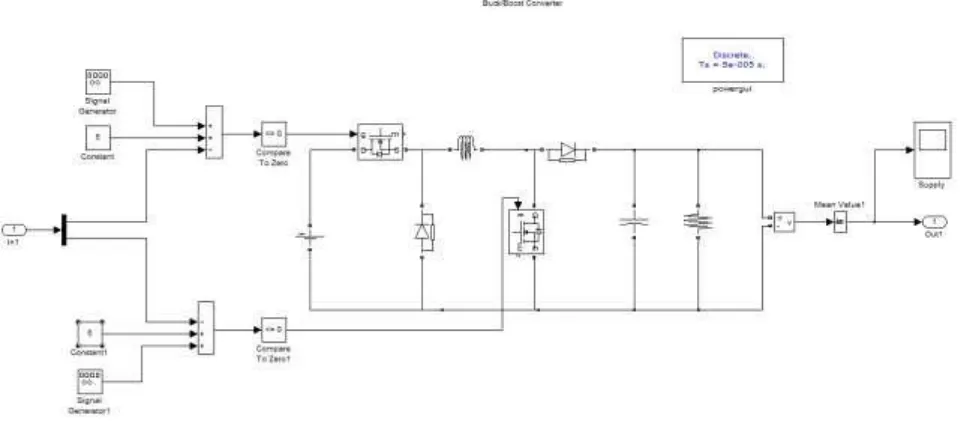
Figure 4. Open loop control of buck-boost converter
The buck-boost converter is operated in buck mode by controlling the switch T1. Switch T2 is kept in open condition. Here we want to keep output voltage at 20V. The error voltage is supplied to the PID controller which is then compared with the inductor current to obtain the switching pulse to the switch T1. Here inductor current is taken as the state variable.
The buck-boost converter is operated in boost mode by controlling the switch T2. Switch T1 is kept in open condition. Here also we are trying to keep output voltage at a constant level of 20V. The error in the output voltage is fed to the PID controller which is then compared with the inductor current to determine the switching pulses to be given to switch T2. Inductor current is taken as the state variable.
Figure 6. Simulated Result Of Output Voltage - Buck Mode
Figure 7. Applied PWM Signal To Switch – Buck Mode
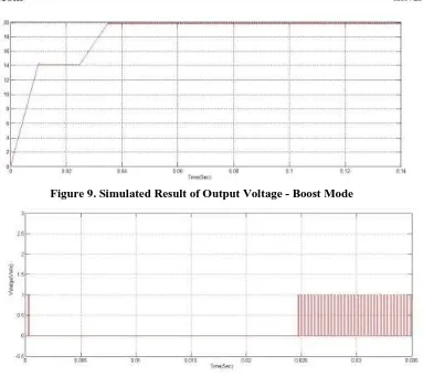
Figure 9. Simulated Result of Output Voltage - Boost Mode
Figure 10. Applied PWM Signal To Switch - Boost Mode
VI. SIMULATION RESULT
Performance of PID and MPC controller for buck-boost converter is studied using MATLAB Simulink model. Unlike model predictive controller (MPC), PID controller directly compares the collected data value with a reference data value, and then use the compared error value for the new input in order to minimize it and keep the system data value reach and stay at the set point [9]. The parameters of PID controllers used in the calculation must be tuned according to requirements of system performance.
Figure 12. MPC Controlled Buck-Boost Converter
A Simulink model for studying the performance of MPC on buck-boost converter has been developed. MPC Controller Toolbox in MATLAB is used for designing MPC controller.
Figure 13. Simulated Result Of Output Voltage – Mpc Controller
VII FUTURE SCOPE
VIII. CONCLUSION
MATLAB simulation of buck-boost is carried out for both PID and MPC controller. Results are compared for the two controller. MPC is found to show better results compared to conventional PID controller. Compared to the PID control, MPC shows better result. Time taken to reach the set value is considerably less in case of MPC control. Output follows the set-point more accurately. In case of PID control the output reaches the set value of 20 V in 0.35 seconds, whereas in case of MPC controller the output reached set pint in less than 0.2 seconds. The results showed the advantage of MPC for dealing with the system dynamic over PID and could be designed for more complex and fast system dynamics even in presence of constraints.
REFERENCES
[1] Benjamin J Patella, Aleksandar Prodic, Art Zirger, Dragan Maksimovic, High-frequency digital PWM controller IC for DC-DC converters, IEEE Transactions on Power Electronics, 18(1), 2003, 438-446 [2] Arnold, M., & Andersson, G. (2011, August). Model predictive control of energy storage including
uncertain forecasts. In Power Systems Computation Conference (PSCC), Stockholm, Sweden.
[3] Spinu, V., Oliveri, A., Lazar, M., & Storace, M. (2012, October). FPGA implementation of opti mal and approximate model predictive control for a buck-boost DC-DC converter. In Control Applications (CCA), 2012 IEEE International Conference on (pp. 1417-1423). IEEE.
[4] Mariéthoz, S., Mäder, U., & Morari, M. (2009, November). High-speed FPGA implementation of observers and explicit model predictive controllers. In IEEE IECON, Ind. Electronics Conf., Porto, Portugal.
[5] Seborg, D., Edgar, T. F., & Mellichamp, D. (2006). Process dynamics & control. John Wiley & Sons. [6] Gopi, S., Vaidyan, V.M(2013, December). Implementation of FPGA based model predictive control
for MIMO systems . In Systems, Process & Control (ICSPC), 2013 IEEE Conference on (pp. 21-24). IEEE.
[7] Sreesha, C., Vaidyan, V. M., & Vaidyan, M. V. (2013, December). Novel petrinet and labview based approaches for automation of small scale soap industry with FPGA and comparative evaluation. In Systems, Process & Control (ICSPC), 2013 IEEE Conference on (pp. 25-30). IEEE.
[8] Thangavelu, A., Varghese, M. V., & Vaidyan, M. V. (2012, September). Novel FPGA based controller design platform for DC-DC buck converter using HDL Co-simulator and Xilinx System Generator. In Industrial Electronics and Applications (ISIEA), 2012 IEEE Symposium on (pp. 270-274). IEEE.
![Figure 1. Hierarchy of process control[5]](https://thumb-us.123doks.com/thumbv2/123dok_us/9260476.1464366/2.595.220.320.305.637/figure-hierarchy-of-process-control.webp)