Design and Simulation of E and U shape
Microstrip PatchAntenna for Biomedical
Applications on HFSS
Amit Kirti Saran, Ramit Kirti Saran, Geeta
B-Tech Student, Dept. of Electronics and Communication Engineering,Apex Institute of Technology, APJ Abdul Kalam Technical University, Lucknow, U.P, India
B-Tech Student, Dept. of Electronics and Communication Engineering,Apex Institute of Technology, APJ Abdul Kalam Technical University, Lucknow, U.P, India
Assistant Professor, Dept. of Electronics and Communication Engineering, AIT, Rampur, Uttar-Pradesh, India
ABSTRACT: This paper exhibits the outline and creation of E and U shape microstrip patch radio wire (antenna) for wideband application. The shape will instigates the expansive transfer speed which is required in different applications as biomedical application (treatment of disease, tumour, and so on.), correspondence, air ship, rocket applications, and so forth. Coaxial feed procedure is utilized as a part of the test. The execution of the outlined receiving wire was resolved in term of bandwidth, gain, return loss, VSWR, and radiation pattern. The design was optimized to meet the best possible result. Substrate utilized Roger RT/duroid 6010/6010(tm) which has a dielectric constant of 10.2. The result demonstrates the wideband radio wire (antenna) to work from 5.289 to 6.4580 GHz frequency band with ideal resonant frequency at 5.57 GHz.
KEYWORDS: E and U shape microstrip patch radio wire (antenna) with SMA Connector technique, HFSS (High Frequency Structural Simulator) adaptation 13.0.
I. INTRODUCTION
Microstrip antenna is popular for low profile applications at frequencies above 100MHz. It consists of a very thin Metallic strip placed an small fraction of wavelength above the ground plane. The ground plane and strip are separated by a dielectric sheet referred to as substrate. In high-performance aircraft, spacecraft, satellite, and missile applications, where size, weight, cost, performance, ease of installation, and aerodynamic profile are constraints, and low-profile antennas may be required. Presently there are many other government and commercial applications, such as mobile radio and wireless communications that have similar specifications.
(a) Microstrip Antenna (b) Side view(c) Coordinate system of each radiating slot
In fig (a), here a dielectric is sandwich in between the ground plane and patch. This patch is excited by a coax feed method.
Fig (b) in this figure a side view of microstrip patch antenna which shows the field inside the dielectric. The maximum radiation occurs at the corner and minimum at the center.
Fig(c)this figure shows antenna operated in spherical coordinates system i.e. (r,θ,∅). This shows the azimuthal and polar angle for microstrip patch antenna.
There are many advantages of microstrip antenna are of smaller size, light weight which occupies very less volume and are easily comfortable to non-planar surface. It is a versatile as it can be designed to produce variety of patterns and polarization, compatible for embedded antenna in handheld wireless devices such as cellular phones and pagers.
But the major operational disadvantages of
microstrip antennas are their low efficiency, low power, high Q(sometimes in excess of 100),very narrow frequency bandwidth, which is typically only a fraction of a percent or at most a few percent.
II.
A
NTENNATHEORYANDDESIGNHere in the microstrip patch antenna , the patch plane is separated from ground by a dielectric constant(
r), having height h. there are basically four ways to excite or provide wave guide to antenna, namely ˡ inset, ²coax(SMA connector), ³aperture coupling, and proximity coupling. In generally inset feed method is not used because of low bandwidth, that‟s why we use SMA connector (coax method) for its large bandwidth.Figure.2 SMA Connector of microstrip antenna
There are also various other ways to enhance the bandwidth of an antenna usually by increasing the height of dielectric constant, also by changing the feed point inantenna, using multiple resonance, using folded patch and using slotted radiating element.
Figure.3 microstrip of E and U shaped patch antenna
In this design an Roger RT/duroid 6010/6010(tm) has been used realize broadband characteristics. This design uses substrate material with relative permittivity (ε) of 10.2. The dielectric constant of a microstrip antenna affects both its radiation pattern and bandwidth. As the dielectric constant of the substrate increases, the antenna bandwidth decrease which increasesthe Q factor of the antenna and therefore decreases the bandwidth but this effect can be reduced to a great extent by increasing the size of substrate. The patch is a combination of inverted E and inverted U. SMA connector, having a coax of „vacuum‟ and a probe of „pec‟ material whose dielectric constant is 1.
III. DESIGN EQUATIONS
To design a patch some mathematical calculations are required. For this purpose some equations are proposed here: To determine the width of a patch plane i.e. the width of main patch(E) shape is given by:
2
2
1
2
r r r rc
Vo
W
f
f
(1)Where
Vo
is the speed of light in free space,f
r is resonant frequency,
r is dielectric constant,h is a height of asubstrate.
Determine the effective dielectric constant of the microstrip antenna using (2)
1
1
12
1
2
2
r r reffh
W
(2)Once Wis found using (1), determine the extension of the length
L
(
0.3)(
0.264)
(0.412)
(
0.258)(
0.8)
ref ref
W
h
L
h
W
h
(3)The actual length of the patch can now be determined from equation (4) L
2
2
reffC
L
L
fr
(4)The bandwidth of antenna calculated by
Band Width = (
f
hf
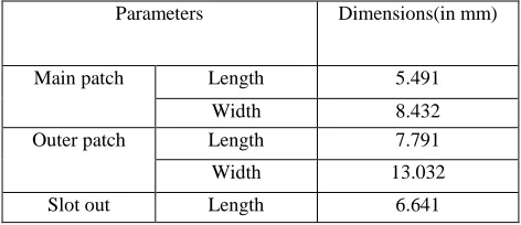
l) (5)Table 1. Design parameter of microstrip patch antenna
Parameters Dimensions(in mm)
Main patch Length 5.491
Width 8.432
Outer patch Length 7.791
Width 13.032
Width 10.732
Rectangles 1,2 Length 4.491
Width 1
SMA connector(coax)
Radius 1.2
Dielectric 1
position 0
Probe Radius 0.697
Position 0
Substrate and Ground
Length 60
Width 60
Height(substrate) 3.2
IV. RESULTS AND DISCUSSION
The simulation and experimental studies of the antenna are done using Ansoft HFSS software respectively. Fig 4 shows the simulated return loss characteristics of the proposed antenna. The value of return loss at 5.6125 GHz is -50.72db and for 6.01 GHz the value of return loss is -58.35. Return loss occur just because of the Reflection due to the mismatching of source to load. As the return loss increases in negative, it shows the matching is improving at the resonant frequency.
The obtained bandwidth is 1.169, which is very wide and suitable for WLAN, PDA, and Bluetooth etc. Because of higher bandwidth data transfer rate is very high. As we increase the bandwidth the channel capacity also increases.
Figure.4 Return loss graph of antenna
Figure.5. VSWR graph of optimized wideband antenna
Figure 6 this is a 3D radiation pattern of microstrip patch antenna which shows the maximum amount of radiation in the Z-direction. In this design we have minimized the minor as well as side lobe to improve the antenna parameters. This figure shows that there is no reflection/radiation in Z-direction that means no back lobe. The radiation pattern or antenna pattern describes the relative strength of the radiated field. The obtained gain of antenna is 9.3db at resonant frequency.
Table 2. Antenna Parameters
Quantity Value Units
Max U 0.0069243 W/st
Peak directivity 10.024 Peak gain 9.3767
Radiated power 0.008681 W Accepted Power 0.0092799 W Incident power 0.017401 W Radiation Efficiency 0.93546
Peak Realized Gain 5.0006
Here from the table 2, represents the antenna parameters which are obtained after simulation of this design, which shows our obtained peak gain is 9.37, peak directivity is 10.02, incident power, radiated power, accepted power, Max U, and a peak realized gain is 5.00 which are very use full.
V. CONCLUSION
An antenna simulation is done on High Frequency Structure Simulator HFSS (High frequency structural simulator) version 13.Based on the simplified formulation that has been described, a design procedure is outlined which leads to practical designs of rectangular microstrip antennas. The design procedure begins with determining the length, width, height of patch plane by formulae which are given above and also we specify the dielectric constant,Then using the measurements obtained above simulation has been setup for the basic rectangular microstrip antenna and the parameters are optimized for the best impedance matching.
Then the dielectric substrate of 10.2 is used to enhance the bandwidth also increase the gain of antenna.
In this paper E and U Microstrip patch antenna is designed on HFSS, for various applications like WLAN, PDA‟s, and Bluetooth etc. Here E and U microstrip patch antenna is excited by a coax feed method, the material of dielectric is RT duroid 6010(tm). The obtained result of this antenna is peak gain of 9.37db, peak directivity is 10.024db and antenna efficiency is 93%, the minimum value of VSWR for this antenna is 0.0210 at 6.0175 GHz resonant frequency. In future, these antenna parameters can be more improved by parametric studies or changing the dimension of antenna.
ACKNOWLEDGEMENTS
The authors like to express their thanks to the department of ECE of Apex Institute of Technology, Rampur for their continuous support and encouragement during this work.
REFERENCES
1. C.A. Balanis, Antenna Theory, 2nd ed. New York: John Wiley & Sons, Inc., 1997. 2. J.D. Kraus, „Antennas‟, 1988, McGraw-Hill
3. Ge, Y.; Esselle, K.P.; Bird, T.S.; , "E-shaped patch antennas for high speed wireless networks," Antennas and Propagation, IEEE Transactions on , vol.52, no.12, pp. 3213- 3219, Dec. 2004
4. B.-K. Ang and B.-K. Chung, "A wideband e-shaped microstrip patch antenna for 5 - 6 GHz wireless communications," Progress In
Electromagnetics Research, Vol. 75, 397-407, 2007.
5. Yang, F.; Xue-Xia Zhang; Xiaoning Ye; Rahmat-Samii, Y.; "Wide-band E-shaped patch antennas for wireless communications," Antennas and
Propagation, IEEE Transactions on , vol.49, no.7, pp.1094-1100, Jul 2001
6. Hadian, A.M.; Hassani, H.R.; , "Wideband Rectangular Microstrip Patch Antenna with U-Slot," Antennas and Propagation, 2007. EuCAP 2007. The
7. Vedaprabhu, B.; Vinoy, K.J.; , "A double U-slot patch antenna with dual Wideband characteristics," Communications (NCC), 2010 National
Conference on , vol., no., pp.1-4, 29-31 Jan. 2010
8. Smith, R. A., D. Saslow, K. A. Sawyer, W. Burke, M. E. Costanza, W.P. Evans, R. S. Foster, E. Hendrick, H. J. Eyre, and S. Sener, \American cancer society guidelines for breast cancer screening: Updated 2003,"CA: A Cancer J for Clinician, 141{169, 2003}.
9. P. Katehi, N. Alexopoulos, and I. Hsia, "A bandwidth enhancement method for microstrip antennas,, vol.35 no.1, pp.5-12, Jan 1987.
10. I. B. Pauria, Sachin Kumar, Sandhya Sharma”Design and Simulation of E-Shape Microstrip Patch Antenna for Wideband Applications”International
Journal of Soft Computing and Engineering (IJSCE) ISSN: 2231-2307, Volume-2, Issue-3, July 2012 11. Micro Lambda, "E+ SMA connectors & Hermetic Seals," SMA connectors datasheet, 2011.
12. Vedaprabhu, B.; Vinoy, K.J.; , "A double U-slot patch antenna with dual Wideband characteristics," Communications (NCC), 2010 National
Conference on , vol., no., pp.1-4, 29-31 Jan. 2010
13. Kumar, G., and K. P. Ray. Broadband Microstrip Antennas. Boston: Artech House, 2003.
14. M. Converse, E. J. Bond, S. C. Hagness, and B. D. Van Veen, “Ultrawide-band microwave space-time beamforming for hyperthermia treatment of breast cancer: a computational feasibility study,” IEEE Transactions on Microwave Theory and Techniques, vol. 52, no. 8, pp. 1876–1889, 2004. 15. K. Planche and S. Vinnicombe, “Breast imaging in the new era,” Cancer Imaging, vol. . 4, pp. 39–50, 2004.
16. K. F. Tong, K.M. Luk,K.F. Lee, and S.M.Shum, “ Analysis of a broadband U-slot microstrip antenna,” 10th international conference on Antenna and propagation, pp 14-17, April 1997, conference publication no.436, IEEE 1997.
BIOGRAPHY
Amit Kirti Saran presently studying B.Tech degree in Department of ECE, under APJ Abdul Kalam Technical University at Apex Institute of Technology, Rampur, Uttar-Pradesh, India. His research interest research areas include Antennas and communication systems.
Ramit Kirti Saran presently studying B.Techdegree in Department of ECE, under APJ Abdul Kalam Technical University at Apex Institute of Technology, Rampur, Uttar-Pradesh, India.His area of interest is signal systems and microwave communications.