Dynamic Voltage Compensation for Smart Electric Grid
Stabilization and Utilization
Mr. B.Rajendra Prasad Tenali
Assistant Professor, Department of Electrical and Electronics, B.V.C College of Engineering, Rajahmundry, A.P., India
ABSTRACT
This paper presents a novel modulated power filter compensator (MPFC) scheme for the smart grid stabilization and efficient utilization. The MPFC is controlled by a novel tri-loop dynamic error driven inter coupled modified PID controller. The MATLAB digital simulation models of the proposed MPFC scheme has been fully validated for effective power quality (PQ) improvement, voltage stabilization, power factor correction and transmission line loss reduction. The proposed FACTS based scheme can be extended to distributed/dispersed renewable energy interface and utilization systems and can be easily modified for other specific stabilization, compensation requirements, voltage regulation and efficient utilization.
INTRODUCTION
A power quality problem is defined as any variation in voltage, current or frequency that may lead to an equipment failure or malfunction. In a modern electrical distribution system, there has been a sudden increase of nonlinear loads, such as power supplies, rectifier equipment used in telecommunication networks, domestic appliances, adjustable speed drives, etc. These power-electronic-based loads offer highly nonlinear characteristics.
Due to their non-linearity, the loads are simultaneously the major causes and the major victims of power quality problems. Harmonics, voltage sag/swell and persistent quasi steady state harmonics and dynamic switching excursions can result in electric equipment failure, malfunction, hot neutral, ground potential use, fire and shock hazard in addition to poor power factor and
inefficient utilization of electric energy manifested in increase reactive power supply to the hybrid load, poor power factor and severely distorted voltage and current waveforms. To improve the efficiency, capacitors are employed which also leads to the improvement of power factor of the mains.
Passive filters are traditionally used to absorb harmonic currents because of low cost and simple robust structure. But they provide fixed compensation and create system resonance . The filtering characteristics of passive filters are determined by the impedance ratio of the supply and the passive filter and are often difficult to design.
The shunt active filters are used for providing compensation of harmonics, reactive power and/or neutral current in ac networks, regulation of terminal voltage, suppression of the voltage flicker, and to improve voltage balance in three phase system.
They have the capability of damping harmonic resonance between an existing passive filter and the supply impedance, but they require a large current rating with high current bandwidth and do not constitute a cost-effective harmonic filtering solution for nonlinear loads.
Hybrid filters effectively mitigate the problems of both passive filters and pure active filter solutions and provide cost effective and practical harmonic compensation approach, particularly for high power nonlinear loads.
The combination of low cost passive filters and control capability of small rating active filter
effectively improve the compensation
the rating of the active filters, compared to pure shunt or series active filter solutions.
Many power filter compensation
configurations are proposed in literature to enhance power quality and to improve power factor .The paper validated a novel modulated power filter compensator (MPFC) scheme, designed by the First Author, to improve the power quality and utilization in smart grid application.
The proposed FACTS based system utilizes the tri-loop dynamic error-driven modified PID controller to control the MPFC. The proposed scheme proved success in improving the power
quality, enhancing power factor, reduce
transmission losses and limit transient over voltage and inrush current conditions
MODIFIED POWER FILTER
COMPENSATOR (MPFC):
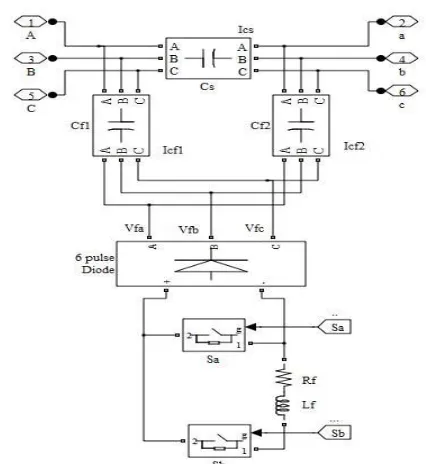
The low cost modulated dynamic series-shunt power filter and compensator is a switched type filter, used to provide measured filtering in addition to reactive compensation. The modulated power filter and compensator is controlled by the on-off timing sequence of the pulse width modulation (PWM) switching pulses that are generated by the dynamic tri loop error driven dynamic modified PID controller. The modified PID controller is equipped with a supplementary error-sequenced compensation loop for fast effective dynamic response in addition to conventional PID activation
Fig. 1 Modified Power Filter Compensator structure
This scheme of MPFC structure comprises a series fixed capacitor bank and two shunt fixed capacitor banks are connected to a modulated PWM switched tuned arm filter through six pulse uncontrolled rectifier. The MATLAB model of this scheme structure is shown in Fig. 1
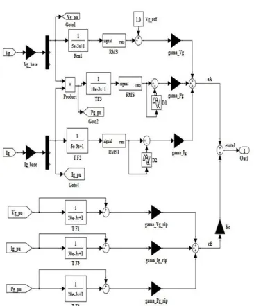
TRI LOOP ERROR DRIVEN MODIFIED PID CONTROLLER:
The tri-loop error-driven dynamic
controller is a novel dual action control used to modulate the power filter compensator. The global error signal is an input to the modified PID controller to regulate the modulating control signal to the PWM switching block as shown in Figs. 2a & 2b. The modified PID includes an error sequential activation supplementary loop to ensure fast dynamic response and affective damping of large excursion, in addition to conventional PID Structure
Fig. 2b MATLAB functional model of the Inter-coupled tri loop error driven modified PID controller
Fig. 3 The single line diagram of the unified EHV study AC system
4. AC STUDY SYSTEM
The sample study AC grid network is shown in Fig. 3. It comprises a synchronous generator (driven by steam turbine) delivers the power to a local hybrid load (linear, non-linear and induction motor load) and is connected to an infinite bus through 300 km transmission line. The system, compensator and controller parameters are given in the Appendix
5. DIGITAL SIMULATION RESULTS
The Matlab digital simulation results using
MATLAB/SIMULINK/Sim-Power Software
Environment for the proposed MPFC scheme under three different study cases are: 5.1. Normal Loading Operation Case The dynamic responses of voltage, current, reactive power, power factor, (THD)v, (THD) i, (FFT)vand (FFT)i
at generator bus (Vg), load bus (VL) and infinite bus (Vb) under normal operation are shown Figs. 4-12. The RMS of voltage and current waveforms of the MPFC are shown in Fig. 13 and Fig. 14. The modulated tuned power filter switching signals that are generated bythe dynamic tri loop error driven dynamic modified PID controller are shown in Fig. 15. The stable voltage signal of synchronous generator power system stabilization (PSS) is depicted in Fig. 16. The Transmission line losses are shown in Table I
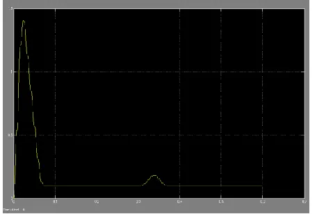
Fig.4 The RMS voltage at AC buses under normal operation ,Generator bus
Fig.4,bThe RMS voltage at AC buses under normal operation, load bus
Fig 5b The RMS current at AC buses under normal operation,load Bus
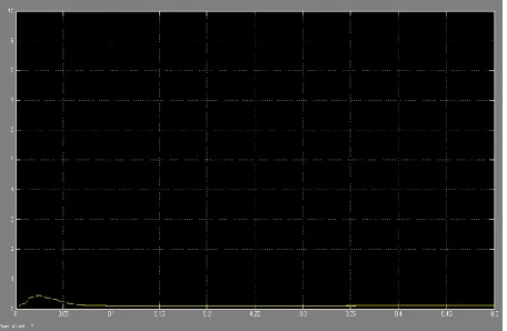
Fig 6aThe reactive power at AC buses under normal operation ,Generator Bus
Fig 6b The reactive power at AC buses under normal operation,Load Bus
Fig 7a The power factor at AC buses under normal operation,Generator Bus
Fig 7b The power factor at AC buses under normal operation, Load Bus
Fig 8a The RMS voltage at the infinite bus under normal operation
Fig 8b The RMS current at the infinite bus undernormal operation
Fig 9b The power fator at the infinite bus undernormal operation
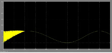
Fig 13The voltage waveforms of MPFC
Fig 14 The current waveforms of MPFC
Fig 14
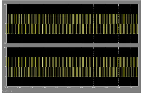
Fig 15 15 Sa and Sb pulsing signals
Fig 16 PSS stable voltage signal
The previous figures confirm the compansation effecteveness as well as the harmonic filtering of the proposed MPFC.
Short Circuit Fault Condition Case
Fig 17a The RMS voltage at generator bus under short circuit (SC) fault condition at bus V
Fig 17b The RMS voltage at load buse under short circuit (SC) fault condition at bus V
Fig 18a The RMS current at generator bus under short circuit (SC) fault condition at bus V
Fig 18b The RMS current at load bus under short circuit (SC) fault condition at bus V
As shown in Figs. 17&18, with using the proposed MPFC scheme, the remote short circuit fault has not any effect on the values of RMS voltage and RMS current of generator and load buses, so these schemes can be considered a good power quality mitigation method.
Hybrid Local Load Excursions Case
The real time dynamic responses of the system for a load excursion are obtained for the following time sequences.
- At t = 0.1 sec, linear load is disconnected for a duration of 0.05 sec.
- At t = 0.2 sec, nonlinear load is disconected for a duration of 0.05 sec.
- At t = 0.3 sec, the induction motor torque is decreased by 50% for a duration 0.05 sec.
- At t = 0.4 sec, the induction motor torque is increased by 50% for a duration 0.05 sec.
Fig 19a The RMS voltage waveform at the generator bus under load excurtions
19b The RMS voltage waveform at the load bus under load excurtions
Fig 20a The RMS current waveform at the load bus under load excurtions
Fig 20b The RMS current waveform at the load busunder load excurtions
Fig 21a The linear load RMS current waveforms
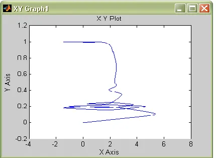
Fig 22The speed-torque relationship of the induction motor
Comparing the dynamic response results without and with using the proposed MPFC under three study cases; normal operation, short circuit fault conditions and hybrid load excursion, it is quite apperent that the proposed MPFC enhanced the
power quality, improved power factor,
compansated the reactive power, stabilized the buses voltag and reduced the transmission line losses.
CONCLUSIONS
This paper presents a novel modulated switched power filter compensator (MPFC) scheme. The MPFC is controlled by a dynamic tri-loop dynamic error driven modified PID controller. The digital simulation model of the proposed MPFC scheme has been validated for effective power quality improvement, voltage stabilization, and power factor correction and transmission line loss reduction. The proposed FACTS based
scheme can be extended to other
distributed/dispersed renewable energy interface and utilization systems and can be easily modified
for other specific compensation requirements, voltage stabilization and efficient utilization. Topology variations and flexible dynamic control techniques can be utilized in renewable energy smart grid interface.
APPENDIX 1) Steam turbine
Pout= 600 MW, speed = 3600 rpm.
2) Synchronous generator 3 phase, 1 pair of poles, Vg = 25 kV (L-L), Sg= 600 MVA, Xd=1.79, Xd'=0.169, X d"=0.135, Xq=1.71, Xq'=0.228, Xq"=0.2, Xl=0.13.
3) Local Hybrid AC Load (90 MVA) linear load: 30 MVA, 0.85 lag pf.
non-linear load: P= 20 kw, Q=22.4 MVAR. induction motor: 3phase, 30 MVA,
no of poles=4,
Stator resistance and leakage inductance (pu) Rs =0.01965 , Ls =0.0397
Rtator resistance and leakage inductance (pu) Rr= 0.01909, Lr =0.0397
Mutual inductance Lm (pu) =1.354 4) Transmission Line
VL-L= 500 kV, 300 km length, R/km=0.01273 Ω, L/km=0.9337 mH
5) Infinte Bus:VL-L= 500 kV
6) MPFC: Cs=30μF, Cf1= Cf2 = 125μF, Rf = 0.25Ω and Lf= 3mH
7) Controller gains (figure 2): γvg=1, γig=0.5, γpg=0.25, γvgrip=1, γig-rip=1, γpg-rip=0.5, Ke=0.1, kp=10, ki=5, kd=0.5 and
PWM frequency fs=1750 Hz.
REFERENCE
[1] J. Arrillaga, D. A. Bradley, P. S. Bodge, Power System Harmonics, Wiley, 1985.
[2] D. Daniel Sabin and Ashok Sundaram, “Quality Enhances”, IEEE Spectrum, No. 2, PP. 34-38, 1996.
power filter", Proc of the IEEE Inter. Symp. on Industrial Electronics, pp 616-621, 1995.
[4] M. Rastogi, N. Mohan, and A.-A. Edris, “Hybrid-active filtering of harmonic currents in power systems,” IEEE Trans. Power Delivery, vol. 10, no. 4, pp. 1994–2000, Oct. 1995.
[5] H. Fujita and H. Akagi, “Apractical approach to harmonic compensation in power system-series connection of passive, active filters,” IEEE Trans. Ind. Applicat., vol. 27, no. 6, pp. 1020–1025, Nov./Dec. 1991.
[6] A. M. Sharaf, Caixia Guo and Hong Huang,“Distribution/Utilization system voltage stabilization and power quality enhancement using intelligent smart filter”, UPEC’95, England, UK, 1995.
[7] M. Aredes, K. Heumann, and E. H. Watanabe, “An universal active power line conditioner,” IEEE Trans. Power Delivery, vol. 13, no. 2, pp. 545–557, Apr. 1998.
[8] M. Rastogi, N. Mohan, and A.-A. Edris, “Hybrid-active filtering of harmonic currents in power systems,” IEEE Trans. Power Delivery, vol. 10, no. 4, pp. 1994–2000, Oct. 1995.
[9] H. Fujita and H. Akagi , “A hybrid active filter for damping of harmonic resonance in industrial power system,” IEEE Trans. Power Electron., vol. 15, no. 2, pp. 215–222, Mar. 2000.