An Isolated Multiport DC-DC Converter for
Different Renewable Energy Sources
K.Pradeepkumar
1, J.Sudesh Johny
2PG Student [Power Electronics & Drives], Dept. of EEE, Sri Ramakrishna Engineering College, Coimbatore, Tamil
Nadu, India1
Assistant Professor, Dept. of EEE, Sri Ramakrishna Engineering College, Coimbatore, Tamil Nadu, India2
ABSTRACT: This paper presents a new isolated multiport dc–dc converter for concurrent power management of several renewable energy sources which can be of similar types. The proposed dc–dc converter uses only one controllable switch in each port to which a source is connected. It has simple configuration and minimum number of power switches. The proposed converter is applied for simultaneous maximum power point tracking (MPPT) control of a wind/solar hybrid generation system consisting of one Wind Turbine Generator (WTG) and two different Photovoltaic (PV) panels. The experimental results are provided to validate the incisiveness of using the proposed converter to achieve MPPT simultaneously for the WTG and both PV panels.
KEYWORDS: Multiport converter, maximum power point tracking (MPPT), photovoltaic (PV), wind turbine generator (WTG) solar energy, wind energy.
I.INTRODUCTION
Nowadays, there is a growing interest in generating electricity from distributed renewable energy sources. In numerous applications, it is required to connect multiple renewable energy sources of different types to a power grid or load. The multiport DC-DC converter has been proposed to efficient power management and grid integration for the multiple origins and development in a new era in a demand quality power in remote communities[8][9]. The isolated dc–dc converter has multiple input ports for connecting different sources, such as photovoltaic (PV) panels, wind turbine generators (WTGs), fuel cells, etc., The multiport dc–dc converter not only regulates the low-level dc voltages of the sources to a constant high level required by the inverter but also provides other important control functions, such as maximum power point tracking (MPPT).
The proposed isolated multiport dc–dc converter for simultaneous power management of multiple renewable energy sources uses only one power electronic switch in each input port connected to a source. The proposed converter does not use any controllable switch on the secondary side of the transformer [2]-[4]. The proposed converter has the least number of switches and thereby a lower cost. The newly introduced converter is applied for power management of a wind/solar hybrid generation systems, which consists of a WTG and two varied PV panels. The power generation from solar and wind energy are designed using perturbation and observation (P&O) MPPT algorithm, in which the WTG and PV panels can be controlled at the same time and extract the maximum power.
II.PROPOSED ISOLATED MULTIPORT DC-DC CONVERTER
MPPT
Fig 1 Block Diagram of the proposed system
Fig 2 Circuit Diagram of the isolated multiport dc–dc converter
The fig 2 shows the circuit diagram of the isolated multiport dc-dc converter. It consists of a low-voltage side (LVS) circuit and a high-voltage-side (HVS) circuit connected by a high-frequency transformer TX. The LVS circuit consists
of m ports in parallel, one energy storage capacitor𝐶𝑠, and the primary winding of the transformer. Each port contains a
controllable power switch, a power diode, and an inductor. The HVS circuit consists of the secondary winding of the transformer connected to a full bridge diode rectifier, and a low frequency LC filter.The transformer’s turn ratio is defined as n= 𝑁𝑝 𝑁𝑠 .
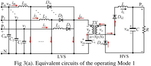
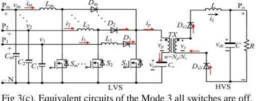
This converter has three operating modes: 1) All switches are on; 2) Switch 𝑆1 is off while at least one of the other switches is on; and 3) All switches are off. The equivalent circuits of the converter in the three operating modes are shown in Figure3.
Fig 3(a). Equivalent circuits of the operating Mode 1
Fig 3(b). Equivalent circuits of the Mode 2:𝑆1 is off and at least one of the other switches is on.
The fig 3(b) which shows the equivalent circuit diagram of mode 2 i.e., switch 𝑆1 is off and at least one of the other
switches is on and also signal flows in the generation system managed by the proposed dc-dc converter.
Fig 3(c). Equivalent circuits of the Mode 3 all switches are off.
The fig 3(c) which shows the equivalent circuit diagram of mode 3 i.e., all switches are off and also signal flows in the generation system managed by the proposed dc-dc converter.
To facilitate the explanation of the converter operation, the state-space equations for different modes are written in the following form:
M * 𝑋 = A * X + B --- (1)
where M = diag(𝐿1, 𝐿2, . . . , 𝐿𝑚,𝐶𝑠 , L,C) is a (m + 3) × (m + 3) diagonal matrix, X = [𝑖1, 𝑖2, . . . , 𝑖𝑚, 𝑣𝑐𝑠, 𝑖𝐿 , 𝑣𝑑𝑐]T is a (m + 3) × 1 state vector, A is the (m + 3) × (m + 3). Coefficient matrix, and B is a (m + 3) × 1 vector containing input signals and some state variables.
The proposed converter is applied for MPPT control of a wind/solar hybrid generation system consisting of a WTG and two PV panels, as shown in Fig 3.
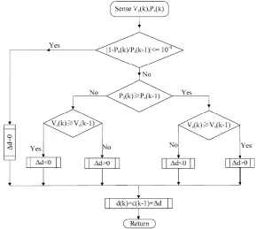
Figure 5 flowchart of the P&O MPPT algorithm
The flowchart of the P&O MPPT algorithm is shown in Fig. 5, where Vs(k) and Ps (k) are the sampled voltage and
power of each source at the kth step, respectively, and ∆d is a predefined perturbation value of the switch duty cycle in
two consecutive switching periods. The updated duty cycle causes a change in the source current, which leads to the variation of the output power of the source. The power variation and duty cycle perturbation in the previous step are used to determine the direction (i.e., positive or negative) of the duty cycle perturbation in the next step.
To test the MPPT results for the two PV panels and the WTG, it is necessary to obtain the ideal maximum power points
(MPPs) of the three sources under various conditions. For a PV panel, the power–voltage (P–V ) characteristic curve
can be assumed unchanged within every 3-min interval in a clear day. Then, the MPPs can be derived by gradually increasing the duty ratio from a low to a high value.
III.SIMULATION OF THE PROPOSED SYSTEM
The proposed converter is applied for MPPT control of a wind/solar hybrid generation system consisting of a WTG and two PV panels, as shown in the Simulink model. The MPPT controller uses a P&O MPPT algorithm to maximize the
output power of the WTG and two PV panels. Since the wind flow changes the updating frequency of 𝑑1is set to be the
highest.
Fig 6 Simulation circuit for the proposed system
The Fig 6 shows the simulation circuit of proposed multiport DC-DC converter which is connecter through the two PV panel and Wind Turbine Generator and it is connected to the load through the inverter.
IV. SIMULATION RESULTS
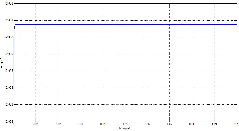
The following results shows the output voltage and current waveforms of PV panel and wind turbine generator
Fig 7(a) PV panel 1 output Voltage waveform
Fig 7(b) PV panel 2 output voltage waveform
The fig 7(b) shows the result of PV panel 2 has the output voltage of approximately 27 V.
Fig 7(c) Wind turbine generator output voltage waveform
V. SIMULATION OUTPUT RESULTFROM INVERTER
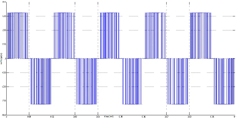
Fig 8 Inverter output voltage waveform
The fig 8 shows the inverter output result for the proposed system. The results are obtained using light load connected to the inverter terminal.
VI.CONCLUSION
An isolated multiport dc–dc converter that uses the minimum number of switches has been proposed for simultaneous power management of multiple renewable energy sources. The proposed converter has been applied for simultaneous power management of a three-source wind/solar hybrid generation system. The experimental results have been provided to show the effectiveness of the proposed converter. The advantage of the proposed multiport dc–dc converter is its simple topology while having the capability of MPPT control for different renewable energy sources simultaneously. Moreover, the proposed converter can be easily applied for power management of other types of renewable energy sources.In future the hybrid energy system can be further altered to some other renewable sources like PV-Fuel cell Hybrid Energy System to meet large load depending on various applications.
REFERENCES
[1] Z. Wang and H. Li, “An integrated three-port bidirectional DC-DC converter for PV application on a DC distribution system,” IEEE Trans. Power Electron., vol. 28, no. 10, pp. 4612–4624, Oct. 2013
[2] H. Matsuo, T. Shigemizu, F. Kurokawa, and N. Watanabe, “Characteristics of the multiple-input DC-DC converter,” IEEE Trans. Ind. Electron., vol. 51, no. 3, pp. 625–631, Jun. 2004.
[3] Y. Chen, Y. Liu, and F. Wu, “Multi-input DC/DC converter based on the multiwinding transformer for renewable energy applications,” IEEE Trans. Ind. Appl., vol. 38, no. 4, pp. 1096–1104, Aug. 2002S.
[4] C. Zhao, S. Round, and J. Kolar, “An isolated three-port bidirectional DC-DC converter with decoupled power flow management,” IEEE Trans.Power Electron., vol. 23, no. 5, pp. 2443–2453, Sep. 2008. J. Kassakian and T. Jahns, “Evolving and emerging applications of power electronics in systems,” IEEE J. Emerging Sel. Topics Power Electron., vol. 1, no. 2, pp. 47–58, Jun. 2013.
[5] O. Lucia, I. Cvetkovic, H. Sarnago, D. Boroyevich, P. Mattavelli, and F. C. Lee, “Design of home appliances for a DC-based nanogrid system: An induction range study case,” IEEE J. Emerging Sel. Topics Power Electron., vol. 1, no. 4, pp. 315–326, Dec. 2013.
[6] J. Carr, J. Balda, and A. Mantooth, “A high frequency link multiport converter utility interface for renewable energy resources with integrated energy storage,” in Proc. IEEE Energy Convers. Congr. Exposit., Sep. 2010, pp. 3541–3548.
[7] W. Qiao, A. Sharma, J. Hudgins, E. Jones, and L. Rilett, “Wind/solar hybrid generation-based roadway microgrids,” in Proc. IEEE Power Energy Soc. General Meeting, Jul. 2011, pp. 1–7.