Subband Array Implementations for
Space-Time Adaptive Processing
Yimin Zhang
Center for Advanced Communications, Villanova University, Villanova, PA 19085, USA Email:[email protected]
Kehu Yang
Electronic Engineering Research Institute, School of Electronic Engineering, Xidian University, Xi’an, Shaanxi 710071, China
Email:[email protected]
Moeness G. Amin
Center for Advanced Communications, Villanova University, Villanova, PA 19085, USA Email:[email protected]
Received 1 January 2004; Revised 30 June 2004
Intersymbol interference (ISI) and cochannel interference (CCI) are two primary sources of signal impairment in mobile commu-nications. In order to suppress both ISI and CCI, space-time adaptive processing (STAP) has been shown to be effective in perform-ing spatio-temporal equalization, leadperform-ing to increased communication capacity as well as improved quality of service. The high complexity and slow convergence, however, often impede practical STAP implementations. Several subband array structures have been proposed as alternatives to STAP. These structures provide optimal or suboptimal steady-state performance with reduced implementation complexity and improved convergence performance. The purpose of this paper is to investigate the steady-state performance of subband arrays with centralized and localized feedback schemes, using different decimation rates. Analytical ex-pressions of the minimum mean-square error (MMSE) performance are derived. The analysis assumes discrete Fourier transform (DFT)-based subband arrays and considers both unconstrained and constrained weight adaptations.
Keywords and phrases:space-time adaptive processing, subband array, array processing, mobile communications, intersymbol interference, cochannel interference.
1. INTRODUCTION
The applications of wireless communications are rapidly ex-panding from voice transmission to a wide class of mul-timedia information. With such increasing needs, wireless communication systems are developing toward higher-speed digital wireless networks. The communication channels are often frequency selective, as a result of long multipath de-lays relative to the symbol period, causing intersymbol in-terference (ISI). In many mobile communication systems, where the frequency resource is reused, cochannel interfer-ence (CCI) represents another source of channel distortion and signal impairment. Therefore, ISI and CCI are two pri-mary sources that limit the communication capacity and the quality of services in mobile communications.
While adaptive arrays are effective for spatial process-ing of CCI suppression; whereas adaptive equalizers are ef-fective for temporal filtering for ISI reduction, neither of them are effective when both the CCI and ISI are present.
The subband (including frequency-domain) adaptive ar-rays can be classified, in terms of their feedback methods, into two classes, namely, centralized feedback and local-ized feedback. In [7], the partial feedback scheme was also introduced as a generalization of the above schemes. For the centralized feedback schemes, Compton has shown that the frequency-domain array provides identical steady-state performance of the corresponding STAP system [15]. Such equivalence, however, is valid only for the undecimated (win-dow sliding) cases. The use of decimation may provide sig-nificant system complexity reduction in subband array im-plementations. The analysis of the performance degradation with the use of decimation has been recently considered by Tran et al. [8] only for ISI without taking the CCI signals into account. On the other hand, for the localized and par-tial feedback schemes, low computations, parallel processing, and faster convergence can be achieved at the cost of sub-optimal steady-state performance [3,7]. Although the inves-tigation of localized subband arrays, according to Compton [15], dated back to early 1970s [16], a detailed performance analysis, to our knowledge, was not available until recently [7,8]. In [7], the performance of discrete Fourier transform (DFT) filter bank-based subband arrays has been consid-ered for the aforementioned three feedback schemes where no decimation is applied. In [8], the performance of local-ized feedback subband array is analyzed for the DFT-based subband arrays in the absence of CCI users. The results of [8] show that, in a frequency-selective multipath fading en-vironment, the subband array performance depends on the number of subbands, input signal-to-noise ratio (SNR), the source directions-of-arrival (DOAs), and the multipath time delays. In addition to the above literature, [3] provides var-ious numerical comparison results between the centralized and localized feedback schemes.
In this paper, we investigate the performance of DFT-based subband arrays with different decimation rates. Both unconstrained and constrained subband array structures are considered. To consider the minimum mean-square error (MMSE) performance, the reference signal is considered to be available. The steady-state performances of subband adaptive arrays with the centralized and localized feedback schemes and different decimation rates are analyzed, and ex-pressions for the MMSE are derived. It is shown that decima-tion compromises the optimum performance for both cen-tralized and localized feedback subband array schemes. The convergence performance of different subband array struc-tures is also investigated and compared.
It is worth noting that there is an extensive literature in frequency-domain equalizations and echo-cancellation methods using single-sensor receivers (see, e.g., [17,18,19, 20] and references therein). These methods provide a fun-damental development in the theory of subband process-ing. However, important differences exist between single-and multi-sensor systems in both formulations single-and perfor-mances. The inclusion of the spatial domain to subband sig-nal processing affects both the processing structure and the performances. Single-antenna receivers cannot deal with the cancellation of CCIs. In addition, we specifically address the
problem of subband arrays with arbitrary decimation rates for both centralized and localized feedback structures.
The rest of this paper is organized as follows.Section 2 introduces the signal model and reviews the analysis of STAP performance. Section 3 considers the subband decomposi-tion, and the aliasing issue with the use of decimation. Section 4formulates the subband arrays with both central-ized and localcentral-ized feedback schemes. The steady-state per-formance of different subband array structures is analyzed in Section 5. Section 6 compares the computational com-plexity between the subband arrays and conventional STAP systems. Section 7 considers the convergence performance where data self-orthogonalization and the step-size selection are addressed. Numerical examples are provided inSection 8 for illustration.
2. SPACE-TIME ADAPTIVE PROCESSING
2.1. Signal model
We consider a base station using an antenna array ofN sen-sors withPusers. Without loss of generality, the user signal of interest is denoted ass1(n). The signals from other users
assp(n),p=2,. . .,P, form the CCIs to the signal of interest.
When frequency-selective channels are considered for each user, the received data vector at the array is expressed as
x(t)=x1(t),. . .,xN(t)
T
=
P
p=1
∞
i=−∞
sp(i)hp(t−iT) + b(t),
(1)
where the superscript T denotes matrix or vector transpose, sp(n) and hp(t) are the nth information symbol and the
channel response vector (including the pulse shaping) of the pth user, respectively, and b(t) is the additive noise vector.
The data vector is sampled att=nT+i∆, whereTis the symbol duration of the signal waveform and ∆is the sam-pling period. The integer ratio ofJ = T/∆is referred to as the oversampling factor. Then, the data vector takes the fol-lowing discrete-time expression:
x(nT+i∆)=
P
p=1
∞
d=0
sp(n−d)hp(dT+i∆) + b(nT+i∆).
(2)
We make the following assumptions.
(A1) The time required for the received waveform as-sociated with a given transmission path to propagate across the array is much smaller than the inverse of the user signal bandwidth.
(A2) The user signalssp(n), p = 1, 2,. . .,P, are
wide-sense stationary (if sampled at the symbol rate, i.e.,J=1) or cyclostationary (if sampled at fractionally spaced symbol cy-cle, i.e.,J >1). These signals are independent and identically distributed (i. i. d.) withE[sp(n)s∗p(n)]=1, whereE(·)
(A3) All channels hp(t), p =1, 2,. . .,P, are linear time-invariant, and of a finite duration within [0, (Dp + 1)T],
whereDpare nonnegative integers.
(A4) The noise vector b(n) is zero-mean and temporally and spatially white with varianceσat each array sensor.
Under these assumptions, we can stack the J samples within each symbol period resulting in the followingNJ×1 vector containing data received at theNJvirtual channels (or extended channels):
2.2. Space-time adaptive processing
When aJM-tap FIR filter is used at the output of each array sensor, or equivalently, anM-tap FIR filter is used at each of theNJvirtual channel, we obtain aMNJ×1 vector that con-tains all the input values at the STAP system at time instant n:
Then, we represent allMsymbol samples captured at theNJ virtual channels of the STAP as
x(n)=
P
p=1
Hpsp(n) +b(n). (7)
Denotew∗ as the weight vector corresponding tox(n). Then the output of the STAP becomes
y(n)=wHx(n), (8)
where the superscript H denotes Hermitian (conjugate trans-pose) operation. When a training signal, which is an ideal
replica of s1(n), is available at the receiver, the optimum
weight vector under the MMSE criterion can be provided us-ing the Wiener-Hopf solution:
wopt=R−o1ro (9)
wherevis a delay [21], which is chosen to minimize the fol-lowing MMSE:
MMSE=Es1(n−v)−wHoptx(n) 2
=1−rH
oR−o1ro. (11)
Substituting (7) in (10), and using assumption (A2), we have
ro=H1ev, (12)
yields only one effective weight for each virtual channel. The optimum value ofvusually occurs around (M+D1)/2−1,
but the actual result depends on the channel characteristics. Typically,J is chosen as either one or two [23]. In addi-tion, it can be shown [21] that, when the channels meet the following conditions:
(1) H1is full column rank,
(2) the columns of H1 are linearly independent of the
columns ofHp,p=2,. . .,P,
the selection ofMandNsatisfying
MNJ≥column rank{H} (14)
yields perfect equalization conditions in noise-free scenarios, whereH=[H1,. . .,HP]. When allHp,p=1,. . .,P, are full
column rank, the above requirement is equivalent to
M≥ 1
3.1. Subband decomposition and subband arrays
convergence and reduce the performance loss in localized feedback schemes [7,21,25,26]. To achieve effective decor-relation between subband signals, the analysis filters are re-quired to be close to the ideal bandpass filters [5,26,27]. This necessitates the use of long analysis filters (i.e., filters with long taps) and, therefore, is usually not desirable. Long analysis filters not only imply a long time delay in the pro-cess of subband decomposition and reconstruction of the signals, but also apply a strict condition to the stationarity of the channel. More importantly, for nonblind subband ar-ray systems, long analysis filters yield ineffective use of the training signals. For these reasons, we consider, in this pa-per, DFT-based filter bank, where the transform matrix of the analysis filters is square. We maintain that long analysis filters remain useful in certain application scenarios such as blind spatio-temporal equalization and echo-cancellation applica-tions, where the training signal is not a problem.
Combining the subband signal processing and array pro-cessing results in subband array propro-cessing. So far, sev-eral subband arrays have been proposed for spatio-temporal equalizations [3,4,5,6,7,8,9,10,12]. For DFT-based sub-band arrays, the performance without decimation has been discussed in [7], whereas the performance with decimation is analyzed for CCI-free situations in [8]. In the latter, only the maximum decimation is considered, that is, the decima-tion rate is the same as the number of subband bins, resulting in a blockwise subband array scheme.
In this paper, we deal with more general cases of DFT-based subband arrays of arbitrary decimation ratesL. That is, for each set of data processed in the subband array process-ing,Loutput data ofy(n) are used. As a result, the process-ing window slides everyLsymbols. It also implies that the weights are updated everyLsymbols. The decimation rate is chosen between one (i.e., no decimation) and the num-ber of subband binsM(i.e., maximum decimation), namely, 1≤L≤M.
3.2. Consideration of decimation
One important issue to be considered in decimated subband signal processing is the alias problem. For simplicity of no-tation and explanation, we illustrate this problem by using a convolution problem for only one of the array sensors.
In the time domain, the output at theith-array sensor amounts to the convolution of a data stream xi(n) and the
weight vector ˜wi = [wi,1,. . .,wi,Q]T. To study the effect of
decimation, we consider a block of input data expressed by a vector ˜xi(n)=[xi(n),. . .,xi(n−M+1)]T, whereM≥Q. Since
the weight vector is updated independently in each block, we adopt the save method, rather than the overlap-add method [17].1Overlap-add method can also be used for
frequency-domain processing, but it requires special atten-tion, since it adds up convolution results of different blocks within which the weight vector may assume different values
1The concepts underlying the overlap-save and overlap-add methods are given in [28,29]. The use of these two methods in subband signal processing is discussed in [17].
0 M−1
˜ xi(n)
0 Q−1
˜ wi
0 Q−1 M−1 M+Q−1
˜ xi(n)∗wi˜
0
Q−1 M−1 M−Q+ 1 Q−2
Q−1
˜ xi(n)∗wi˜ (PeriodM)
Figure1: Illustration of alias problem (“∗” denotes the convolu-tion operator).
[30]. Referring toFigure 1, the convolution of ˜wiand ˜xi(n)
yields a new vector of length M +Q−1, of which, only M−Q+ 1 samples (from theQth sample to theMth sample) take full consideration ofQdata inputs. The rest are incom-plete, in the sense that the output samples do not use allQ input data. In this case, zero-padded data are used instead.
When DFT-based filter banks are used to construct a sub-band array, the data vector, along with the weight vector, is transformed into the subband domain. After the data vector and the weight vector are multiplied in the transform do-main, the result is transformed back to the time domain by using the inverse DFT (IDFT).
It is noticed that the weight vector can be constrained such that, in each virtual channel, only the firstQvalues of its time-domain equivalence are nonzero, whereQ≤M. In the constrained subband arrays, the lengths of data and weight vectors as well as the dimension of DFT can be different. With the use of anM-point DFT transform, the convolution of M-tap data andQ-tap weights yieldsM−Q+ 1 points of alias-free output samples. That is, the decimation rate can take the valueL≤M−Q+ 1 without causing an alias prob-lem. It is pointed out that the alias-free results are achieved at the cost of reduced number of degrees of freedom fromMto Q, which, as we will show later, does not necessarily improve the system performance.
4. SUBBAND ARRAYS
4.1. Formulation of subband array signals
In this section, we formulate the expression of a DFT-based subband array withMsubbands and a decimation factor of L. Let the subband decomposition divide theM samples of data sequence at the output of theith virtual channel,
˜
intoMsubbands, that is, to form the vector
˜
by the following equation:
˜ themth subband is obtained as
x(Tm)(n)=xT(m,1)(n),x
as theMNJ×1 signal vector for all theMsubbands in the subband array, we can relatexT(n) andx(n), defined in (5),
by
xT(n)=Tx(n), (21)
where the transform matrixTis expressed in the form
T=To⊗INJ (22)
and⊗denotes the Kronecker product operator. It is easy to confirm thatTis also unitary, that is,TTH=THT=I
MNJ.
4.2. Adaptive subband arrays
Denote by (w(Tm))∗theNJ×1 weight vector to the signal vec-tor xT(m)(n) at themth subband, and bywT∗ = [(w(1)T )T,. . .,
(w(TM))T]HtheMNJ×1 weight vector to the entire subband
signal vectorxT(n). The subband output is obtained as the
followingM×1 vector:
˜yT(n)=
is anMNJ×Mmatrix. The time-domain output is the last L interested samples out of theM samples of the IDFT of
˜yT(n), expressed as
matrix, and theMNJ×Mmatrix
X(n)=XT(n)T−o1UL (27)
Unconstrained subband arrays
We first consider the unconstrained subband array structure. To help the derivation, we consider the following weight up-date equation based on the LMS algorithm:
wT ←−wT+µXT(n)˜e∗T(n), (28)
whereµis a scalar representing the step size,2 and˜e
T(n) is
theM×1 error signal vector at the transform domain. As we discuss below, the error signal vector is different for the two different feedback schemes. To avoid confusion, nota-tions˜eT,CF(n) and˜eT,LF(n) will be used to specify the
cen-tralized and localized feedback schemes, respectively, for the error vector in the transform domain˜eT(n).
In the centralized feedback scheme, for each block of sub-band array processing, the error between the reference signal and the subband array output is minimized in the time do-main overLsamples, that is,3
˜e(n)=UL˜s1(n−v)−ULT−o1˜yT(n)
=UL
˜s1(n−v)−To−1XTT(n)w∗T
=UL˜s1(n−v)−XT(n)w∗T.
(29)
The corresponding error vector at the subband domain
˜eT,CF(n) is the DFT of the time-domain error and is expressed
as
˜eT,CF(n)=To˜e(n)=ToUL
˜s1(n−v)−To−1XTT(n)wT∗
, (30)
where
˜s1(n)=
s1(n+M−L) · · · s1(n) · · · s1(n−L+ 1)
T
(31)
is a block ofMsymbol values of the reference signal. On the other hand, for the localized feedback scheme, the error between the reference signal and the subband ar-ray output is minimized independently at each subband. The error signal vector˜eT(n) becomes
˜eT,LF(n)=˜sT(n−v)−˜yT(n)
=To˜s1(n−v)−XTT(n)w∗T.
(32)
By comparing (30) and (32), it is evident that, while the centralized feedback scheme minimizes the error over theLsamples, the localized feedback scheme minimizes the error at all the M samples independent of the decimation rate. In particular, when L = M, that is, the subband ar-ray is maximally decimated, UL = IM and, subsequently,
˜eT,CF(n)=˜eT,LF(n). Therefore, the centralized and localized
feedback schemes have the identical performance when the subband arrays are maximally decimated.
2The selection of step size is discussed inSection 7.
3It is noted that, although the same notation is used for the STAP system and different subband array schemes, the optimum value ofvcould differ in different implementations, even under the same signal environment.
Constrained subband arrays
For constrained subband arrays, the weight vector is updated according to
wT ←−wT+µFXT(n)˜e∗T(n), (33)
where
F=ToUQT−o1
⊗INJ=TUQNJT−1 (34)
is used to convert the transform-domain information into the time domain, mask the weights to onlyQnonzero values (L = M−Q+ 1), and then convert the results back to the transform domain, with
UQ=
IQ OQ×(M−Q) O(M−Q)×Q O(M−Q)×(M−Q)
,
UQNJ =
IQNJ OQNJ×(M−Q)NJ
O(M−Q)NJ×QNJ O(M−Q)NJ×(M−Q)NJ
.
(35)
It is clear that, under the same DFT transform dimensional-ity, the constrained subband array algorithm achieves alias-free convolution at the cost of sacrificing the degrees-of-freedom of the independently controllable weights.
For the constrained subband array structure, (29)–(32) remain valid with the understanding that not every element ofwT can be independently optimized.
5. STEADY-STATE PERFORMANCE ANALYSIS
This section derives the expressions of the steady-state MMSE performance. The performance of the unconstrained subband array structure is derived in Section 5.1, whereas, that of the constrained structure is derived inSection 5.2.
5.1. Unconstrained subband arrays
We first consider the performance of the centralized feedback subband arrays. From (28) and the orthogonality principle, E[XT(n)˜e∗T,CF(n)]=0at the steady state. Note thatTHo =T−o1
andTT
o=To, and therefore,
EXT(n)˜e∗T,CF(n)
=EXT(n)T∗oUL
˜s∗1(n−v)−T−1
o
∗
XH
T(n)wT
=MEX(n)˜s∗1(n−v)−X(n)XH(n)w
T
=Mr−RwT
=0,
(36)
where
R=EX(n)XH(n),
The optimum weight vector is the Wiener-Hopf solution
wT,CF,opt=R−1r. (38)
Using the above equation and (29), it is straightforward to obtain the MMSE of the time-domain output error:
MMSECF=1
Similarly, for the localized feedback scheme,
EXT(n)˜e∗T,LF(n) Therefore, the optimum weight vector is
wT,LF,opt=R−T1rT, (42)
and the corresponding MMSE is obtained as
MMSELF=
where Re(·) denotes the real-part operator.
It can be shown that, whenL = 1, that is, when there is no decimation, the MMSE of a centralized feedback sub-band array is the same as the MMSE of the corresponding STAP system [7,15]. Compared with a subband array using the centralized feedback scheme, a subband array with the lo-calized feedback scheme provides inferior performance when L < M, and the performance of the two feedback schemes be-comes identical whenL=M. In this case,RT =R,rT =r,
and (39) is identical to (43).
5.2. Constrained subband arrays
To derive the steady-state performance of the constrained subband arrays, we premultiply (33) byT−1. Using
expres-sion (34), we obtain the following weight update equation in the time-domain equivalence:
It can be shown that [31]
XT(n)=√1
MTX(n)T −1
o . (46)
Substituting (46) in (44) yields
T−1w
elements are zero. From (47), it is clear that, at the steady state,
EXQ(n)To−1˜e∗T(n)
=0 (48)
is satisfied.
Denote by ˜wT the weight vector before the constraints,
that is, wT = Fw˜T. For the centralized feedback scheme,
Notice thatRQis of rankQNJand, therefore, is rank deficient
ifQ < M. We define the following matrix pseudoinversion:
Then, the optimum weight vectors are obtained from (49) as
˜
wT,CF,opt=TR#QrQ,
wT,CF,opt=Fw˜T,CF,opt=TUQNJR#QrQ.
(52)
The error signal vector for constrained centralized feedback subband arrays is given by
˜
e(n)=UL˜s1(n−v)−XT(n)wT∗
=UL˜s1(n−v)−XT(n)T∗UQNJ
R∗Q#r∗Q =UL˜s1(n−v)−ULGT
R∗Q#r∗Q,
(53)
and the MMSE is given by
MMSECF=1−
1 Lr
H
QR#QrQ. (54)
For the localized feedback scheme,
EXQ(n)To−1e∗T(n)
=EUQNJX(n)T−o1
T∗o˜s1(n−v)−XTT(n)w∗T
∗
=√MEG(n)˜s∗1(n−v)−G(n)GH(n)T−1w˜T
=√MrQ−RQT−1w˜
T
=0,
(55)
where
RQ=EG(n)GH(n), rQ=EG(n)˜s∗1(n−v)
. (56)
The optimum weight vectors are obtained as
˜
wT,LF,opt=T
RQ#rQ,
wT,LF,opt=Fw˜T,LF,opt=TUQNJ
RQ#rQ, (57) where (RQ)# is the pseudoinversion ofR
Q, which is also of
rankQNJ. The error signal vector for constrained localized feedback subband arrays is given by
˜
e(n)=UL˜s1(n−v)−XT(n)w∗T
=UL˜s1(n−v)−XT(n)T∗UQNJ
R∗Q#r∗Q =UL˜s1(n−v)−ULGT
RQ∗#r∗Q.
(58)
The corresponding MMSE is obtained as
MMSELF
=1 +1 L
rH
Q
RQ#RQRQ#rQ−2RerH
Q
RQ#rQ. (59)
WhenQ =M, a constrained subband array is equal to its unconstrained counterpart. Similar to the unconstrained subband array cases, it can be readily shown that, whenL= M, we haveRQ =RQ,rQ = rQ, and (54) and (59) become
identical.
6. DMI IMPLEMENTATION AND
COMPUTATIONAL COSTS
In this section, we consider the computational costs when the direct matrix inversion (DMI) implementation is applied. We use the number of complex multiplication operations as the measure of the computational cost. The unconstrained subband array structures are considered below. Assuming that the pseudomatrix inversion in (51) consumes roughly the same amount of computations as those of matrix inver-sion, the constrained structures require additional computa-tions of 2NJ M-point FFT to perform the weight masking.
When the DMI algorithm is used, the weight vectors for STAP and the centralized and localized feedback subband ar-rays are computed using the Wiener-Hopf solutions given by (9), (38), and (42), respectively, with the covariance matrices and correlation vectors being replaced by the corresponding estimates obtained from a block of data samples [32]. The dimension of all covariance matrices isMNJ×MNJ.
We focus on the computational costs of computing the weight vector from the Wiener-Hopf solutions, and that for the DFT/IDFT operations required for the subband arrays. The Wiener-Hopf solution is equivalent to the Yule-Walker equation with a general right-hand side. With some modifi-cation to the Levison-Durbin recursions developed for Yule-Walker equation, the computation of the weight vector from the Wiener-Hopf solution, for ap×pcovariance matrix case, requiresO(4p2) complex multiplications4[34].
However, for the localized feedback subband array, the covariance matrixRTis block diagonal. To illustrate the
cor-responding computational requirements, we consider in the manner that the weight vector is updated at each subband in-dependently. The weight vector w(Tm,LF,opt) at themth subband is obtained from
wT(m,LF,opt) =RT(m)−1r(Tm), (60)
where
R(Tm)=Ex(Tm)(n)Hx(Tm)(n) (61)
is theNJ×NJcovariance matrix of x(Tm)at themth subband, and
r(Tm)=Ex(Tm)(n)s(m)(n)∗ (62)
is the correlation vector between x(Tm)and the reference signal s(m)(t) at themth subband.
Therefore, for the subband array using the localized feed-back scheme, the weight vector can be obtained fromM par-allel sets of dimensionNJ×NJmatrix problems.
From the above discussion, it is clear that the compu-tational cost of STAP system is O(4M2N2J2). For the
cen-tralized feedback subband array, the computational cost is O(4M2N2J2) per L symbols, resulting in O(4M2N2J2/L)
flops per symbol. On the other hand, for the localized feed-back subband array, the computational cost isO(4MN2J2)
per L symbols, resulting in O(4MN2J2/L) flops per
sym-bol. In particular, whenL =M, the computational cost for the centralized and localized feedback subband arrays are O(4MN2J2) andO(4N2J2), respectively.
For subband arrays, one must consider the computa-tional cost of DFT/IDFT transforms. For every Lsymbols, NJtimes ofM-dimensional DFT transforms are required at the subband signal decomposition, one time DFT is needed for reference signal decomposition, and one time IDFT is required for the signal synthesis at the subband array out-put. Therefore, the computational cost becomes O((NJ + 2)(M/L) log2M)=O((MNJ/L) log2M) per symbol for both subband array schemes. Therefore, the computational cost of DFT/IDFT transforms is smaller than that of weight compu-tations for the centralized feedback scheme, whereas for the localized feedback scheme, it becomes smaller than that of the weight computations only when log2M <4NJ, which is often satisfied.
7. CONVERGENCE PERFORMANCE
In this section, we consider the convergence performance of the subband arrays. The LMS algorithm is used. To take the advantages of subband array processing for improved con-vergence, we perform self-orthogonalization of the data sig-nals in each subband independently after the subband de-composition [6]. Because the number of the virtual chan-nels (NJ) is usually much smaller than that of the total STAP dimensions (MNJ), the additional computational cost of eigendecomposition at each subband is considerably lower than that of the whole-band subspace approach of subband array or STAP systems [21]. Note that, while power nor-malization is effective in improving the convergence perfor-mance in single-antenna equalizers, the effect of power nor-malization alone is not significant in subband arrays [6].
Consider thekth subband, and letR(Tk)denote theNJ× NJcovariance matrix of subband signal vector x(Tk)(n), and is eigendecomposed as
RT(k)=ExT(n)(t)x(Tk)(n)H=V(k)Λ(k)V(k)H. (63)
The new subband signal vector after the self-orthogonaliza-tion is expressed as
x(Tk)(n)←−Λ(k)−1/2V(k)Hx(k)
T (n). (64)
In practice, the covariance matrixR(Tk)can be approximated using sample averaging or recursive update. Note that, while such data self-orthogonalization makes the comparison
more obvious, it is common for all the subband array schemes and does not favor any specific scheme in the con-vergence performance comparison.
We first consider the unconstrained subband array using the centralized feedback scheme. The mean of the weight er-ror vector can be expressed as [32]
EwT(l)−wT,opt
=1−µRS
l
EwT(0)−wT,opt
, (65)
wherewT(l) denotes the subband-domain weight vector at
thelth iteration. From (28) and (30), the matrixRSis
ob-tained as follows:
(A) centralized, unconstrained:
RS=E
XT(n)T∗oUL
T∗o−1XH
T(n)
. (66)
Therefore, the step size is chosen as
0< µ= α trRS
< 2 trRS
, (67)
where 0 < α <2 is a constant and tr(·) denotes the matrix trace. From (28) and (30)–(33), it is straightforward to derive the matrixRSfor other subband array schemes in the similar
manner as follows:
(B) localized, unconstrained:
RS=E
XT(n)XHT(n)
; (68)
(C) centralized, constrained:
RS=E
FXT(n)T∗oUL
T∗o−1XHT(n); (69)
(D) localized, constrained:
RS=E
FXT(n)XTH(n)
. (70)
For the unconstrained subband array with the localized feedback scheme, the weights are updated independently at each subband. In this case, the step-size parameter at themth subband can be chosen as
0< µ(m)= α
trRS(m)<
2
trR(Sm), (71)
where
(E) localized, unconstrained:
R(Sm)=Ex(Tm)(n)x(Tm)(n)H. (72) In the underlying case, due to self-orthogonalization, it fol-lows that tr(R(Sm))=(1/M)tr(RS) and, therefore, the step-size
parameter µ(m), obtained from (71), isMtimes larger than
−7 −8 −9
−10
−11
−12 −13
0 1 2 3 4 5 6 7 8 9
Unconstrained centralized Unconstrained localized
Constrained centralized Constrained localized L
MMSE
(dB)
(a)
−7 −8
−9 −10
−11 −12
−13
−14 −15
−16 −17
0 2 4 6 8 10 12 14 16
Unconstrained centralized Unconstrained localized
Constrained centralized Constrained localized L
MMSE
(dB)
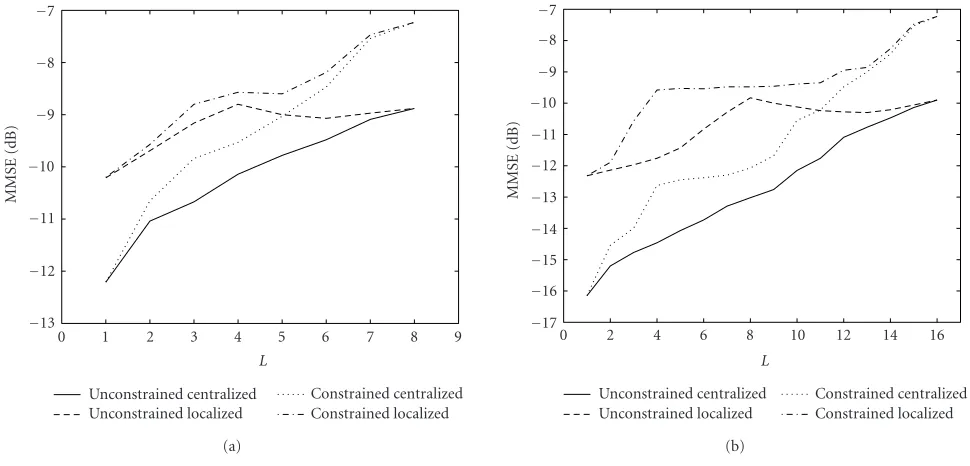
(b) Figure2: MMSE versus the decimation rate: (a)M=8 and (b)M=16.
8. NUMERICAL EXAMPLES
8.1. Steady-state performance
A three-element linear array with half-wavelength interele-ment spacing is considered. Two user signals are illuminating the array. Each has a maximum delay spread of five symbols. Six quasistatic multipath components are randomly gener-ated for each user. The quasistatic channels are assumed to remain constant over the processing period, and to change over time as independent stationary stochastic processes. The mean value of the input SNR is 20 dB for both signals. For each user signal, the input signal power is defined as the total power of all paths. The signals are sampled and processed at the symbol rate (i.e.,J=1).
DMI-like methods are considered in the performance evaluation. One hundred frequency-domain data samples are used for weight and MMSE computations, and the results are averaged over 100 independent trials.
Figure 2shows the MMSE performance, whereM takes the values of 8 and 16, andLassumes a value between 1 and M. For the constrained subband array structure, the num-ber of nonzero weight elements is chosen asQ=M−L+ 1 in each virtual channel. It is evident that the 16-subband ar-ray provides lower MMSE than the 8-subband counterpart. While the change shown inFigure 2is not monotonic due to limited data samples used in the simulations, we maintain that the MMSE generally increases withL.
Among the four schemes of subband arrays, the re-sults show that unconstrained subband array structures out-perform the respective constrained counterparts, and the centralized feedback scheme provides superior performance compared to the localized feedback scheme. As a result, when the same values of M andLare considered, the
un-constrained centralized feedback scheme achieves the best performance, whereas, the constrained localized feedback scheme provides the worst performance.
It is clear from the numerical results that, unlike other structures, the performance of the unconstrained subband arrays with the localized feedback scheme does not change significantly with respect to the decimation rate. This is be-cause the weights are optimized in the frequency domain and, therefore, the subband array does not favor any time-domain samples in a subband block. For the constrained subband arrays, the MSE becomes large as the decima-tion rate increases, because the number of nonzero weights Q = M −L + 1 decreases as the decimation rate L in-creases.
While the decimation compromises the subband array performance, it is however noted, that the use of decimation often greatly reduces the signal processing rate and compu-tational costs. The localized feedback scheme can further re-duce the implementation complexity and it is amenable to parallel implementations. Therefore, the subband arrays in general provide flexible system designs, where performance may be traded offwith the system complexity. Subband ar-rays with decimation and localized feedback schemes may, therefore, provide improved performance to the STAP sys-tem with the same computational costs.
8.2. Convergence performance
0 −2
−4
−6 −8
−10
−12
−14 −16 −18
0 1 2 3 4 5 6 7 8 9 10
×103
Without orthogonalization With orthogonalization
Time (symbol)
MSE
(dB)
(a)
0 −2
−4
−6
−8
−10
−12 −14 −16
0 2 4 6 8 10 12 14 16 18 20
×102 Centeralized
Localized I Localized II
Time (symbol)
MSE
(dB)
(b) 0
−2
−4
−6 −8
−10 −12 −14 −16
0 2 4 6 8 10 12 14 16 18 20
×102 Local, constrained
Local, constrained Central, constrained Central, unconstrained
Time (symbol)
MSE
(dB)
(c)
0 −2
−4
−6
−8
−10
−12
−14
−16
0 1 2 3 4 5 6 7 8 9 10
×102 L=1
L=4, mean value L=8, mean value
Time (iteration)
MSE
(dB)
(d)
Figure3: Comparison of the convergence performance for different subband array schemes. (a) Effect of self-orthogonalization (centralized, M=16,L=1). (b) Convergence performance (M=16,L=1). (c) Convergence performance with respect to symbols (M=16,L=4). (d) Convergence performance with respect to iterations (centralized, unconstrained,M=16).
weights are set to zero. In addition, the MSE is obtained by averaging the results of 100 independent trials.
We first show the effect of data self-orthogonalization at each subband. The subband array with centralized back scheme is used as the example, and the localized feed-back scheme is demonstrated in a similar manner.Figure 3a compares the convergence performance with and without data self-orthogonalization, where the number of subbands is M = 16 and no decimation is applied (L = 1).
Figure 3bshows the convergence performance of the sub-band arrays where no decimation is applied (L = 1). The constrained and unconstrained subband array schemes are identical. For the localized feedback subband array, if the se-lection of the step-size parameterµis guided by (67) (shown as “localized I” in the figure), the convergence performance becomes similar to that of the centralized subband array. On the other hand, when the step-size parameter Mµ is used for the localized feedback scheme (shown as “localized II”), the convergence becomes faster than the centralized coun-terpart, at the expense of larger residual error. Note that the centralized feedback subband array diverges when the step size is set equal toMµ.
InFigure 3c, the convergence is compared for different subband array schemes forL=4. Step sizeµis used for both centralized feedback schemes, whereasMµis used for the lo-calized feedback schemes. It is clear that, because of the re-duction of the degrees of freedom, the constrained feedback schemes provide slightly faster convergence.
Comparing Figures3band3c, it is evident that the dec-imating of the data results in slower convergence. The pri-mary reason behind this is that, in a decimated array, the weights are updated only everyLsamples. InFigure 3d, the convergence performance is compared in terms of the num-ber of iterations, and the convergence for different decima-tion rates (L=1, 4, and 8) are comparable.
9. CONCLUSIONS
We have investigated the MMSE performance of subband ar-rays with arbitrary decimation rates for unconstrained and constrained subband array structures. Both the centralized and localized feedback schemes were considered. Among the four combination schemes of subband arrays, the results showed that when the same number of array and subbands are used, the unconstrained subband array structures outper-form the constrained counterparts, and the centralized feed-back scheme provides superior performance compared to the localized feedback scheme.
ACKNOWLEDGMENT
The work of Y. Zhang and M. G. Amin is supported by the Office of Naval Research Grant no. N00014-98-1-0176.
REFERENCES
[1] A. J. Paulraj and C. B. Papadias, “Space-time processing for wireless communications,” IEEE Signal Processing Magazine, vol. 14, no. 6, pp. 49–83, 1997.
[2] R. Kohno, “Spatial and temporal communication theory us-ing adaptive antenna array,” IEEE Personal Communications, vol. 5, no. 1, pp. 28–35, 1998.
[3] Y. Kamiya and Y. Karasawa, “Performance comparison and improvement in adaptive arrays based on the time and fre-quency domain signal processing,” IEICE Transactions on Fundamentals of Electronics, Communications and Computer Sciences, vol. J82-A, no. 6, pp. 867–874, 1999.
[4] Y. Zhang, K. Yang, and Y. Karasawa, “Subband CMA adap-tive arrays in multipath fading environment,” Electronics and Communications in Japan (Part I: Communications), vol. 83, no. 11, pp. 43–54, 2000.
[5] Y. Zhang, K. Yang, and M. G. Amin, “Adaptive array process-ing for multipath fadprocess-ing mitigation via exploitation of filter banks,”IEEE Trans. Antennas and Propagation, vol. 49, no. 4, pp. 505–516, 2001.
[6] Y. Zhang, K. Yang, and M. G. Amin, “Convergence perfor-mance of subband arrays for spatio-temporal equalization,” in
Proc. 11th IEEE Signal Processing Workshop on Statistical Sig-nal Processing (SSP ’01), pp. 544–547, Orchid Country Club, Singapore, August 2001.
[7] Y. Zhang, K. Yang, M. G. Amin, and Y. Karasawa, “Perfor-mance analysis of subband arrays,” IEICE Transactions on Communications, vol. E84-B, no. 9, pp. 2507–2515, 2001. [8] X. N. Tran, T. Taniguchi, and Y. Karasawa, “Performance
analysis of subband adaptive array in multipath fading envi-ronment,”IEICE Transactions on Fundamentals of Electronics, Communications and Computer Sciences, vol. E85-A, no. 8, pp. 1798–1806, 2002.
[9] Y. Zhang and K. Yang, “Subband adaptive arrays with different decimations,” inProc. IEEE Sensor Array and Multichannel Signal Processing Workshop (SAM ’02), pp. 398–402, Rosslyn, Va, USA, August 2002.
[10] T. Sekiguchi and Y. Karasawa, “CMA adaptive array anten-nas using analysis and synthesis filter banks,” IEICE Trans-actions on Fundamentals of Electronics, Communications and Computer Sciences, vol. E81-A, no. 8, pp. 1570–1577, 1998. [11] A. O. Steinhardt and N. B. Pulsone, “Subband STAP
pro-cessing, the fifth generation,” inProc. IEEE Sensor Array and Multichannel Signal Processing Workshop (SAM ’00), pp. 1–6, Cambridge, Mass, USA, March 2000.
[12] J. M. Khalab and M. K. Ibrahim, “Novel multirate adaptive beamforming technique,” Electronics Letters, vol. 30, no. 15, pp. 1194–1195, 1994.
[13] R. Hudson, D. Korompis, F. Lorenzelli, A. Wang, and K. Yao, “Subband processing for broad-band microphone arrays,”
Journal of VLSI Signal Processing Systems for Signal Image and Video Technology, vol. 14, no. 1, pp. 43–55, 1996.
[14] J. Benesty and D. R. Morgan, “Frequency-domain adaptive fil-tering revisited, generalization to the multi-channel case, and application to acoustic echo cancellation,” inProc. IEEE Int. Conf. Acoustics, Speech, Signal Processing (ICASSP ’00), vol. 2, pp. II789–II792, Istanbul, Turkey, June 2000.
[15] R. T. Compton Jr., “The relationship between tapped delay-line and FFT processing in adaptive arrays,” IEEE Trans. An-tennas and Propagation, vol. 36, no. 1, pp. 15–26, 1988. [16] B. L. Lewis and F. F. Kretschmer Jr., “Naval research laboratory
report of limited distribution,” Tech. Rep., Naval Research Laboratory, Arlington, Va, USA, February 1974.
[17] J. J. Shynk, “Frequency-domain and multirate adaptive filter-ing,”IEEE Signal Processing Magazine, vol. 9, no. 1, pp. 14–37, 1992.
[18] A. Feuer and R. Cristi, “On the steady state performance of frequency domain LMS algorithms,” IEEE Trans. Signal Pro-cessing, vol. 41, no. 1, pp. 419–423, 1993.
[19] B. Rafaely and S. J. Elliot, “A computationally efficient fre-quency-domain LMS algorithm with constraints on the adap-tive filter,” IEEE Trans. Signal Processing, vol. 48, no. 6, pp. 1649–1655, 2000.
[21] K. Yang, Y. Zhang, and Y. Mizuguchi, “A signal subspace-based subband approach to space-time adaptive processing for mobile communications,” IEEE Trans. Signal Processing, vol. 49, no. 2, pp. 401–413, 2001.
[22] K. Yang, Y. Zhang, and T. Ohira, “Array configuration de-sign for space-time adaptive processing systems,” in Proc. IEEE Sensor Array and Multichannel Signal Processing Work-shop (SAM ’02), pp. 145–148, Rosslyn, Va, USA, August 2002. [23] A.-J. van der Veen, “Resolution limits of blind multi-user multi-channel identification schemes—the bandlimited case,” inProc. IEEE Int. Conf. Acoustics, Speech, Signal Processing (ICASSP ’96), vol. 5, pp. 2722–2725, Atlanta, Ga, USA, May 1996.
[24] P. P. Vaidyanathan, Multirate Systems and Filter Banks, Pren-tice Hall, Englewood Cliffs, NJ, USA, 1993.
[25] H. Ochi, Y. Higa, and S. Kinjo, “A subband adaptive filter with the optimum analysis filter bank,” inProc. IEEE Int. Conf. Acoustics, Speech, Signal Processing (ICASSP ’95), vol. 2, pp. 993–996, Detroit, Mich, USA, May 1995.
[26] D. Marelli and M. Fu, “Performance analysis for subband identification,” IEEE Trans. Signal Processing, vol. 52, no. 1, pp. 142–154, 2004.
[27] T. Q. Nguyen, “Near-perfect-reconstruction pseudo-QMF banks,”IEEE Trans. Signal Processing, vol. 42, no. 1, pp. 65–76, 1994.
[28] L. R. Rabiner and B. Gold, Theory and Application of Digital Signal Processing, Prentice Hall, Englewood Cliffs, NJ, USA,
1975.
[29] A. V. Oppenheim, R. W. Schafer, and J. R. Buck, Discrete-Time Signal Processing, Prentice Hall, Englewood Cliffs, NJ,
USA, 2nd edition, 1999.
[30] G. A. Clark, S. R. Parker, and S. K. Mitra, “A unified approach to time- and frequency-domain realization of FIR adaptive digital filters,” IEEE Trans. Acoustics, Speech, and Signal Pro-cessing, vol. 31, no. 5, pp. 1073–1083, 1983.
[31] R. M. Gray, “On the asymptotic eigenvalue distribution of Toeplitz matrices,” IEEE Transactions on Information Theory, vol. 18, no. 6, pp. 725–730, 1972.
[32] S. Haykin, Adaptive Filter Theory, Prentice Hall, Englewood Cliffs, NJ, USA, 3rd edition, 1996.
[33] D. B. Percival and A. T. Walden, Spectral Analysis for Physi-cal Applications: Multitaper and Conventional Univariate Tech-niques, Cambridge University Press, Cambridge, UK, 1993. [34] G. H. Golub and C. F. van Loan,Matrix Computations, Johns
Hopkins University Press, Baltimore, Md, USA, 3rd edition, 1996.
Yimin Zhangreceived the M.S. and Ph.D. degrees from the University of Tsukuba, Tsukuba, Japan, in 1985 and 1988, respec-tively. He joined the faculty of the Depart-ment of Radio Engineering, Southeast Uni-versity, Nanjing, China, in 1988. He served as a Technical Manager at the Communi-cation Laboratory Japan, Kawasaki, Japan, from 1995 to 1997, and was a Visiting Re-searcher at ATR Adaptive Communications
Research Laboratories, Kyoto, Japan, from 1997 to 1998. Since 1998, he has been with the Villanova University, Villanova, Pa, where he is currently a Research Associate Professor at the Cen-ter for Advanced Communications. His research inCen-terests are in the areas of array signal processing, space-time adaptive process-ing, multiuser detection, MIMO systems and cooperative diversity, blind signal processing, digital mobile communications, and time-frequency analysis. Dr. Zhang is a Senior Member of IEEE.
Kehu Yang received the B.E., M.S., and Ph.D. degrees from Xidian University (for-merly, the Northwest Telecommunications Engineering Institute), Xi’an, China, in 1982, 1984, and 1995, respectively. He joined Xidian University in 1985, where he became an Associate Professor in May 1996. From December 1998 to May 2002, he was a Visiting Researcher at ATR Adaptive Com-munications Research Laboratories, Kyoto,
Japan. From June 2002 to October 2002, he was a Research Fellow at Xi’an Research Institute of ZTE Corporation. From November 2002 to December 2002, he was with Xi’an Haitian Antenna Tech-nologies Co., Ltd., as the Leader of the R&D Department 3. In Jan-uary 2003, he rejoined Xidian University as an Associate Professor, and in July 2004, he became a Full Professor at Xidian University. His main research interests are in array signal processing for radar and smart antenna for mobile communications. Dr. Yang is a Mem-ber of IEEE.
Moeness G. Amin received his Ph.D. de-gree in 1984 from University of Colorado, Boulder. He has been on the faculty of Vil-lanova University since 1985, where is now a Professor in the Department of Electri-cal and Computer Engineering and the Di-rector of the Center for Advanced Com-munications. Dr. Amin has over 250 pub-lications in the areas of wireless communi-cations, time-frequency analysis, smart