Hybrid Moth-Flame Fuzzy Logic Controller Based
Integrated Cuk Converter Fed Brushless DC Motor for
Power Factor Correction
K. Kamalapathi 1, Neeraj Priyadarshi 2,*, Sanjeevikumar Padmanaban 3,*, Farooque Azam 4,* , C. Umayal 5, Vigna K. Ramachandaramurthy 6
1,5School of Electrical Engineering, VIT University- 600127, India; [email protected] (K.K), [email protected] (C.U).
2Department of Electrical Engineering, Birsa Institute of Technology (Trust), Ranchi- 835217, India; [email protected] (N.P.).
3 Department of Energy Technology, Aalborg University, 6700 Esbjerg, Denmark
4 School of Computing & Information Technology, REVA University, Bangalore, 560064, India; [email protected] (F.A.)
6 Institute of Power Engineering, Department of Electrical Power Engineering, Universiti Tenaga Nasional,Kajang 43000, Malaysia; [email protected] (V.K.R.)
* Correspondence: [email protected] (N.P.)
Abstract- This research work deals hybrid control system based integrated Cuk converter fed brushless DC motor (BLDCM) for power factor correction. In this work, moth-flame optimization (MFO) and fuzzy logic controller (FLC) has been combined and moth –flame fuzzy logic controller (MFOFLC) has been proposed. Firstly, the BLDC motor modelling is composed with power factor correction (PFC) based integrated Cuk converter and BLDC speed is regulated using variable DC-Link inverter voltage which makes low switching operation with less switched losses. Here, with the use of switched inductor, the task and execution of proposed converter is redesigned. The DBR (diode bridge rectifier) trailed by proposed PFC based integrated Cuk converter operates in discontinuous inductor conduction mode(DICM) for achievement of better power factor.MFO is exhibited for gathering of dataset from the input voltage signal. At that point separated datasets is send to FLC to improve the updating function and minimization of torque ripple. However, our main objective is to assess adequacy of proposed method, the power factor is broke down. The execution of the proposed control methodology is executed in MATLAB/Simulink working platform and the display is assessed with the existing techniques.
Keywords: BLDC (brushless DC) motor; VSI, Fuzzy logic controller; Moth flame optimization;Torque ripples.
1. Introduction
Nowadays a trend to use Brushless DC motor rather than brushed DC motor in an expanding number of uses [1]. Compared to brush DC motors and induction motors, BLDC motor has a couple of favourable circumstances [2]. It works as a synchronous motor in which stator and rotor magnetic field generates comparative frequency. BLDC engines don't encounter the "slip" that is consistently found in induction motors [3]. Regularly, the BLDCM is made out of three stator coils with a permanent magnetic rotor in which magnetic field is turned by 2 coils and floating coil is responsible for back EMF.[4]. Speed regulation is a fundamental viewpoint as far as BLDC speed and position controlling is concerned [5-7].
As an average speed controller framework, it employed double-loop structure which can be used in multiple applications like in household; electronics based self-propelled, précised apparatus and automated systems used in offices, and so forth [8].
Because of torque ripple commutation, BLDC motor has torque ripple problem.. Subsequently, concealment of torque ripplecommutation is responsible for reduction of torque ripple in BLDC motor[9]. The torque for the most part incorporates cogging, mutual, andreluctance torque.Cogging torque has been activated using stator connected rotor’s magnetic field which is independent from stator’s current excitation [10, 11]. Because of power electronic commutation, torque ripples are generated which is responsible for highswitched frequency and stator’s blemish [12]. The trapezoidal back-EMF is responsible for reduction of torque ripples in BLDC motor which can be achieved by utilizing condensed winding and use of one pitch slot with skewed stator slot skewing [13, 14]. Therefore a productive controller is required for minimization of supply voltage and line current harmonics present in motor system [15].
Practically speaking, the design of the BLDC motor drive includes a mind boggling procedure.Traditionally, various BLDC motor speed controller have been discussed in literature [16]. Phase change method, hysteresis current method, pulse width modulation (PWM) controller have already been discussed to smoothen torque ripple in BLDC motor but unable to handle over or under compensation problems [17]. Sensors are employed for rotor speed and position estimations [18]. Proportional Integral (PI) based speed controller has been used for this purpose but has more rise/settled time with high speed oscillations are the major issues [19]. Routinely, least-squares approximation strategy, genetic algorithm (GA), particle swarm optimization (PSO) algorithm, NN (neural network) and enhanced gradient descent algorithm has been discussed to improve speed and positions estimation of BLDC motor [20, 21].
Now a day, regulation of speed and torque with torque ripple minimization is a great concern of BLDX motor. PWM controllers are the best suited technology for controlling BLDC motor in which two-phase feeding scheme has been employed. However, it has vulnerability issue because of load as well as in set speed variations. Additionally, tuning of the PID controller prompts vulnerability in the control system parameters. To overcome these challenges, optimal torque control technique utilizing advanced technology is required. Here, an enhanced controller has been employed which solves above issues. MFO technique, numerous parameters will be considered which will identify with the PFC and torque ripple minimization, for example, the speed, torque, back EMF, torque ripple and so forth individually.Using these parameters, the objective function will be characterized that will be comprehended by the MFO strategy.Simulation results reveal employed controller exhibit and predicts best control signals to the converter. The accompanying section portrays the configuration of the proposed converter.
2. PFC of BLDC Motor utilizing Proposed Technique
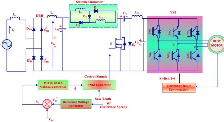
The schematic of proposed BLDC motor correcting power factor scheme with controlling strategy is appeared in Figure 1. Here, the BLDC motor comprises of two phase: modelling and controlling phases. This framework constitutes an AC voltage as input source, voltage source inverter, integrated Cuk converter, MFFLC based controller as main components. In modelling phase, the BLDC motor is associated with three phases of voltage source inverter (VSI). After thatwith respect to neutral point (
N
) the phase voltage is estimated.IGBT are employed for inverter lower frequency execution. In controlling phase, a MFFLC strategy is applied for efficiency enhancement of DC motor through switched inductor operation. Also, BLDC electronic commutation and speed regulation is carried out with PWM pulses to the inverter. Generally, the VSI comprises of six solid-state switches which encounters more switched losses because of higher PWM pulses used in motor speed control.The following sections elaborate proposed system design, BLDC motor modelling and control methodologies.Figure 1. Schematic structure of integrated Cuk converter based controlling strategy for BLDCM
2.1. Modelling Phase
The design of Cuk converter and modelling of BLDC motor is described in this section. Initially, the three phase (AC) supply is given as input source to DBR which is defined in equation (1).
)
sin(
)
(
t
V
t
V
S
m
(1) Where,
2
f
The voltage appearing after DBR is
)
sin(
)
(
t
V
t
V
i
m
(2)The DBR is utilized for converting the input AC voltage to DC voltage and the direct current supply is given to switched inductor.Voltage/current stress occurs while giving DC supply in boost segment and power factor corrected based power switch is expanded in DICM (discontinuous inductor current mode).Consequently, the Cuk converter works as a inverter is [22] which consists of a switch, diode, switched inductors and capacitors. Inductor gets parallel charged in case of switch ON condition and discharge in series during
OFF
condition with same energy level. Here, the switched inductors have beenmainlyutilizedfor transferring supply and output voltages to current source [23, 24]. The following section includes the design and performance of proposed converter with different modes.2.1.1 Design of Integrated Converter with VariousModes
Integrated Cuk converter operates in various modes of Continuous Conduction Mode and discontinuous conduction mode. DICM (Discontinuous Inductor Current Mode) and Discontinuous Capacitor Voltage Mode (DCVM) are treated as two modes of discontinuous conduction mode operation. The Cuk converter execution [25] in CCM is described as following intervals. In the first interval, when switch S is turn
ON
, the switched L1 and L2 store energy while C1 discharge energy which is shown in Figure 2 (a). In the second interval, the S is turnedOFF
, the switched inductor is responsible for energy storing and C1gets discharged using switch (S) which relocates DC link capacitor (C2) depicted with Figure 2 (b).(b)
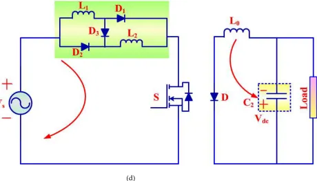
(d)
Figure 2. Design of integrated Cuk converter with different intervals of switching period:(a, b) CCM mode, (c)DICM and (d) DCVM modes
The operation of integrated Cuk converter in DICM and DCVM [26] operation with different intervals of switching period is illustrated using Figure 2 (c) and (d). In first interval, S works in conduction state, the inductor stores energy and discharged in capacitor through switch and energy transferring to C2.While S gets OFF in second state but C1 (intermediate capacitor) completely discharged energy and performs DCM operation; hence no energy is left in switched inductor input and voltage remains zero during this operation. In third interval, the intermediate capacitor starts charging continuously by input inductor L1 during turn off condition.
Then the output summed energy is given to VSI, so that the voltage level is increased. Then, the VSI is connected to the BLDC motor [27] for controlling speed and torque. Figure 3 illustrates the equivalent circuit of motor phase.
Voltage condition of BLDCM is composed of following equation (3).
sabc s s abc s
abc
F
R
I
dt
d
.
.
(3)Where,
r
srepresents stator resistance, stator voltage is
,I
is stator current andF
denotes flux linkage.Stator’s resistance matrix can be calculated in following condition (4).
s s s
s
diagonal
r
r
r
r
,
,
(4)The electromagnetic torque
eis created by considering back-EMF is characterized as
.
3
2
.
1
2
cos
3
2
.
1
2
cos
1
2
.
cos
).
2
(
.
.
.
1
2
1 1 2 1 `
x
N
x
N
N
pF
I
I
I
K
N
r r r m s c s b s a N N e
(5)Evaluation of phase back-EMF voltages at the stator terminalsis carried out by rotating the machine with prime mover and open circuit terminal. The mechanical condition of motor speed is expressed as
e m
j
P
dt
d
.
2
.
(6)Here,
.
dt
d
is the rotor angular speed with respect to
t
, p represents magnetic poles number and
mspecify mechanical torque. In the proposed method the normal and speed reference is estimated from the speed estimator and the torque ripple of BLDC motor are minimized from the control strategy is specified in the below section.
2.2 Controlling Phase
Speed /Torque of BLDCM has been controlled using proposed method based PI (proportional integral) controller is developed. From Figure 1, the output signals from VSI generated the optimal pulses, for controlling motor.
The PI is the feedback control loop mechanism used in control system. Here, the BLDC motor speed is estimated by utilizing the speed estimator. From actual and reference value the speed error is calculated and passed through voltage controller for speed controlling and error correcting. The output of PI controller depends on
K
iandK
pparameters and is specified as)
(
)
(
t
K
e
t
e
K
I
p
s
i
s (7)In general, the proportional gain (
K
p) is providing the entirecontrollingperformance. It can be expressedas proportional to signal error with associated gain and the transfer function is given as follows.
)
(
.
)
)
(
t
K
dt
e
t
e
K
I
best si s
best
p
(8)Where,
e
s
t
V
dc
V
dc*In the proposed controller, by utilizing the FLC method, MFO strategy is executed and updated. Hence, the gain parameters value (
K
bestp ) is stored from the output of the proposed controller algorithm. Thus,the optimal value of poweris controlled and the controlled signal is given to PWM generator for controlling inverter switching operation and BLDC motor performance. The torque ripples is minimized from the following equation (9).
min max min max
t
t
t
t
ripple
(9)For generating the optimal control pulses of motor the torque is applied as input for the proposed method by multiplying with 100 and evaluated the torque ripple percentage. The developed mathematical equation for optimal control signals is formulated as
off ont
t
DC
TH
t
e
t
t
DC
TH
t
e
if
t
DC
)
(
;
)
(
)
(
;
)
(
)
(
(10)Here,
TH
is the threshold value,t
onis on andt
off off period of the switches and the duty cycle isrepresented as
DC
(
t
)
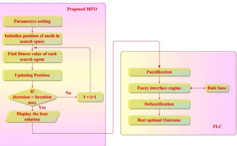
. With the Figure 1 the modelling of BLDC motor is composed.The following section explained the detailed working procedures of proposed MFFLC control approach for getting optimal pulses.3. Proposed MFFLC Algorithm
underlying irregular arrangements and joining to a superior point in the pursuit space.Here, MFO method can be employed to differentiate proper and accessible required orientation with the selection of suitable activation function. In light of fulfilled dataset, the FLC performs and predicts the most ideal control signals of the converter.With this control strategy, the BLDC motor speed and PFC will be regulated; likewise the harmonicsand torque ripples will be minimized.The MFO algorithm consists of following steps.
3.1. Steps for Proposed MFO Algorithm
Step 1: Setting of Parameters
Voltage, currentand speed variables are the deciding parameters. Number of dim variables,
iteration
Max
_
,moths and flames numbers, and lower bound (lb
) and upper bound (ub
) of variables is defined aslb
[
lb
1,
lb
2,
...
,
lb
n1,
lb
n]
andub
[
ub
1,
ub
2,
...
,
ub
n1,
ub
n]
are considered as MFO main parameters.Step 2: Initialization
In MFO algorithm the moths arrangement is initialized in aform of matrix, since it is a population based algorithm.
m n n n m m MA
R
R
A
A
M
M
M
M
M
A
R
R
A
A
A
R
R
A
A
A
, 2 , 1 , , 1 2 , 2 1 , 2 , 1 2 , 1 1 , 1 (11)Where, the matrix location of moths is
A
M,A
i,jis thej
thparameter (variables) value of the moth (i
th) ,.
,
,
2
,
1
R
n
i
andj
1
,
2
,
R
,
m
. By using the random distributionA
i,jcan be given as in equation (12).)
(
))
(
)
(
(
)
,
(
i
j
upper
bound
i
lower
bound
i
rand
lower
bound
i
A
M
(12)Here,
rand
denotes uniform randomly created values lies in [0, 1].Theset of flames are expressed as:
m n n n m mb
K
K
b
b
M
M
M
M
M
b
K
K
b
b
b
K
K
b
b
B
, 2 , 1 , , 1 2 , 2 1 , 2 , 1 2 , 1 1 , 1 (13)Where, the matrix location of flames is
B
,b
i,jrepresents thej
thparameter value ofi
th flame,.
,
,
2
,
1
K
n
Step 3: Determination of Fitness Function
The voltage/current parameters corresponding to BLDC motor are appeared in the moth evaluation.To store the fitness values of moth and flames
OA
MandOB
matrix are employed.
)
(
)
(
)
(
, 2 , 1 , , 2 2 , 2 1 , 2 , 1 2 , 1 1 , 1 2 1 m n n n m m n MA
A
A
f
A
A
A
f
A
A
A
f
OA
OA
OA
OA
(14)
)
(
)
(
)
(
, 2 , 1 , , 2 2 , 2 1 , 2 , 1 2 , 1 1 , 1 2 1 m n n n m mn
f
b
b
b
b
b
b
f
b
b
b
f
OB
OB
OB
OB
(15)The main objective of the activation function of the proposed algorithm is to minimize error generated from reference and measured signal. Also, The
f
i
t
can be expressed mathematically as,
ei
t
V
f
(
)
min
where,V
eis the error signal.Step 4: Position Updating
The each moth position is updated based on the best fitness value and is expressed in equation (16). Here,
t
is the random number,d
is distance andS
is spiral function.j bt
i J
i
B
d
e
t
B
A
S
(
,
)
.
.
cos
(
2
)
(16)Where,
d
i
B
j
A
iDuring spatial orientation, no moths should cross upper limit and when moth becomes closer to flame, preceding parameters should be updated with respect to current parameters. The random number
t
is in interval [r, 1] and iteration processr
decreases with linear relation from -1 to -2.Step 5: Final Process
The adaptive mechanism employed in number of flames over the iterations as follows,
)
1
1
(
_
max max maxT
N
N
round
no
Where,
T
maxandN
maxrepresents the maximal flames number and iteration. Positions of moths have beenupdated by considering best flame from end iterations which provides adjustments of gradually minimization of investigated and searched position. These fulfilled datasets are given to the fuzzy logic controller to perform and predicts the most ideal control signals of the converter.The flowchart of proposed MFO algorithm with FLC is delineated in the Figure 4.
3.2. Prediction of Control Signals Using FLC
The FLC algorithm is utilized to perform and predicts the most ideal control signals of the converter.The procedure of FLC is indicated underneath. FLC controller makes results encourage decisively by improved interest and MFFLC strategy is utilized for power factor correction with parameters gain. (i) Fuzzification Process: With the help of membership function selection, it converts crisp to linguistic parameters [31,32]. The error
E
(
t
)
and the change of errorE
c(
t
)
are considered as supply parameters of FLC which is given as,)
(
)
(
)
(
t
V
t
V
t
E
o
ref (18))
(
)
(
)
(
t
E
t
E
1t
E
g
p
p (19)Where, the reference voltage is
V
ref(
t
)
, the present output voltage isV
o(
t
)
, andp
subscripts denotes theinitial considered parameters.
(ii)Fuzzy Inference Engine: With the application of If-Then fuzzy rules, decisions are taken as:
)
(
)
(
,
THEN
Z
t
is
f
t
B
is
E
and
A
is
E
If
f ii i
c
i (20)
Where,
A
i,B
i andf
i(
t
)
are subsets and singleton parameters, respectively.(iii)De-Fuzzification Process: In this method, fuzzy variables are defuzzified and converted to numerical output.It decides membership ability of output parameters.The outcome of the framework database as,
)
(
)
(
t
Z
t
f
fi
i
(21)Where,
Z
f(
t
)
i is represents the solution of target after fuzzification.
Figure 4. Flow chart of proposed MFFLC method
4. Simulated Results and Discussions
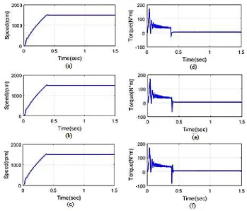
Test Case 1: Analysis of Constant Speed and Torque
Figure 5. Analysis of Speedusing the(a) proposed (b) MFOmethod and (c) PI controller and Torque using the(d) proposed (e) MFOmethod and (f) PI controller
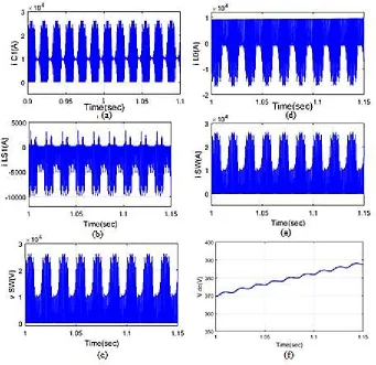
Figure 6 shows the analysis of capacitor and inductor, current and voltage using proposed method. The Figure 6(a-c) shows, the behaviour of proposed drives used inductors and capacitors components for correction of power factor which result improvement of power quality and can be achieved by the complete range of speed control. Figure 6 (d), 6 (e) shows the different operation of switch with optimal voltage/current. By increasing time, DC-link voltage is increases and reached maximum of 387 V, thereby corrected the power it can be seen in Figure 6(f).
Figure 6. Analysis of current using the (a) C1, (b) L1, (d) L0, (e) switch and voltage using (c) switch, (f) DC link
Test Case 2: Analysis of Constant Torque with Speed Variation
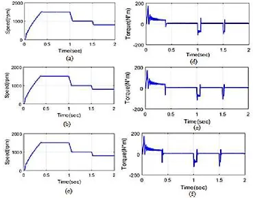
condition. In Figure 8 (f) shows that the time variation in the motor in PI controller is 0 to 0.37 sec due to the constant torque condition.
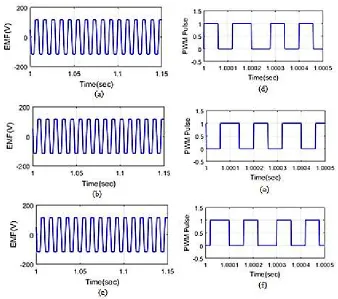
Figure 7. Analysis of EMF using the (a) proposed (b) MFO method and (c) PI controllerand PWM using the (d) proposed (e) MFOmethod and (f) PI controller
Figure 9 shows the analysis of capacitor and inductor, current and voltage using proposed method. Figure 9 (a-c) shows the performance of proposed drive system operates using supply/ output inductor /capacitor for power factor correction. The power quality improvement has been realized by the entire range of speed control. Figure 9 (d), (e) illustrates the different modes of switch working with optimal voltage/current stress. By increment in time period, DC-link voltage is increases and reached maximum of 383 V with a time interval of 0.9 to 1.1sec.
technique generate PWM generates full pulse. But in the existing technique, the PWM generate half the pulse in the proposed technique.
Figure 8. Analysis of Speedusing the (a) proposed (b) MFOmethod and (c) PI controllerand Torque using the (d) proposed (e) MFOmethod and (f) PI controller
Test Case 3: Analysis of Torque Variation with Constant Speed
Figure 9. Analysis of current using the (a) C1, (b) L1, (d) L0, (e) switch and voltage using (c) switch, (f) DC link
Figure 12 shows the analysis of capacitor and inductor, current and voltage using proposed method. Fig 12 (a-c) (i) shows the steady state behaviour of proposed drive system which operates using supply inductor and capacitor with output inductor and capacitor for power factor correction. The enhanced quality of power can be obtained by entire speed adjustment range. Different mode of operation of switch with optimal voltage/ current stress has been explained using Figure 12 (d, e). By increment of time period, DC-link voltage increases and reached maximum of 381 V with a time interval of 0.9 to 1.1s.
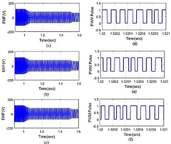
In Figure 13 shows the BLDC motor is optimized as the EMFanalysis for the proposed method, MFO, PI controller operation. In Figure 13, EMF of the proposed method and other techniques time are varied for settling process. Here, the proposed method takes the less time settling process with compare to the existing methods like as MFO and PI controller. The analysis of EMF and PWM output performance of the proposed and existing methods has been illustrated in the Figure13 respectively.
case 3.Hence,by utilizing the proposed strategy the PFC is identified and there is a decrement in ripple torque by half amount in BLDC motor by different speed and torque variation. On the other hand, the existing methods have analyzed to reduce the torque ripples and provide the superiority over the existing methods having more complex computational analysis. Thus, proposed control system enhances the stability and accurateness of drive scheme and reduces complex computation performance by correcting and adding supplementary components associated to conventional approaches.
Figure 10. Analysis of EMF using the (a) proposed (b) MFOmethod and (c) PI controllerand PWM using the (d) proposed (e) MFOmethod and (f) PI controller
Table 1. Power factor of BLDC motor with proposed technique
Methods Case 1 Power factor Case 2 Case 3
Proposed 0.9772 0.9675 0.9428
MFO 0.9542 0.9402 0.9156
Figure 11. Analysis of Speed using the (a) proposed (b) MFOmethod and (c) PI controllerand Torque using the (d) proposed (e) MFOmethod and (f) PI controller
5. Conclusion
Figure 13. Analysis of EMF using the (a) proposed (b) MFOmethod and (c) PI controllerand PWM using the (d) proposed (e) MFOmethod and (f) PI controller
References
1. Priyadarshi, N.; Padmanaban, S.; Mihet-Popa, L.; Blaabjerg, F.; Azam, F. Maximum Power Point Tracking for Brushless DC Motor-Driven Photovoltaic Pumping Systems Using a Hybrid ANFIS-FLOWER Pollination Optimization Algorithm. Energies2018, 11, 1–16.
2. Ibrahim, H.E.A.; Hassan, F.N.;Shomer, A.O.; Optimal PID control of a brushless DC motor using PSO and BF techniques.Ain Shams Engg. J.2014, 5, 371-398.
3. Niapour, S.A.KH.M.;Tabarraie, M.;Feyzi, M.R. A new robust speed-sensor less control strategy for high-performance brushless DC motor drives with reduced torque ripple. Control Engg. Practice. 2014, 24, 42–54. 4. Masmoudi, M.;Badsi,B.E1.;Masmoudi, A. Direct Torque Control of Brushless DC Motor Drives with
Improved Reliability.IEEE Trans. on Ind. Appl. 2014, 50, 3744-3753.
5. Sheng, T.; Wang, X.; Zhang, J.; Deng, Z. Torque Ripple Mitigation for Brushless DC Machine Drive Systems Using One-Cycle Average Torque Control.IEEE Trans. on Ind. Elec. 2015, 62, 2114-2122.
6. Lu, H.; Zhang, L.;Qu, W. A New Torque Control Method for Torque Ripple Minimization of BLDC Motors With Un-Ideal Back EMF. IEEE Trans. on Power Elec.2008, 23, 750-758.
7. Tingna, S.;Yuntao, G.;Peng, S.;Changlian, C. A new approach of minimizing commutation torque ripple for brushless DC motor based on DC–DC converter. IEEE Trans. on Ind. Elec.2010, 57, 3483-3470.
8. Jiancheng, F.;Xinxiu, Z.; Gang, L. Precise Accelerated Torque Control for Small Inductance Brushless DC Motor.IEEE Trans. on Power Elec. 2013, 28, 1400-1412.
9. Devendra, P.; Chandra, K.P.B.; Arasaratnam, I.; Gu, -D.W.; Mary, K.A.; CH,S.B. Derivative-free square-root cubature Kalman filter for non-linear brushless DC motors.IET Electric Power Appl.2016, 10, 417-427.
10. Jiancheng, F.;Xinxiu, Z.; Gang, L. Instantaneous Torque Control of Small Inductance Brushless DC Motor.IEEE Trans. on Power Elec. 2012, 27, 4952-4964.
11. Devendra, P.;Kalyan,Ch.P.; Mary, K.A.; Ch.S.B. Simulation Approach for Torque Ripple Minimization of BLDC Motor Using Direct Torque Control.Int. J. of Adv. Research in Elec., Electronics and Instrum.Engg.2013, 3703-3710.
12. Shanmugasundram, R.;Zakariah, K.M;Yadaiah, N. Implementation and Performance Analysis of Digital Controllers for Brushless DC Motor Drives. IEEE/ASME Trans. on Mechatronics.2014,213-224.
13. Jiancheng, F.;Xinxiu, Z.; Gang, L. Instantaneous Torque Control of Small Inductance Brushless DC Motor. IEEE Trans. on Power Elec.2012, 27, 4952-4964 .
14. Tingna, S.; Yuntao, G.; Peng, S.; Changlian, C. A new approach of minimizing commutation torque ripple for brushless DC motor based on DC–DC converter.IEEE Trans. on Ind. Elec. 2010, 57, 3483-3470.
15. Sathyan, A.; Milivojevic, N.; Lee, -Y.J.; Krishnamurthy, M.;Emadi, A. An FPGA-Based Novel Digital PWM Control Scheme for BLDC Motor Drives. IEEE Trans. on Ind. Elec. 2007,56, 3040-3047.
16. Lee, -B.K.; Kim, T.H.;Ehsani, M. On the feasibility of four-switch three-phase BLDC motor drives for low cost commercial applications: topology and control.IEEE Trans. on Power Elec.2003, 18,164-172.
17. Park, S.J.; Park, H.W.; Lee, M.H.;Harashima, F. A new approach for minimum-torque-ripple maximum-efficiency control of BLDC motor. IEEE Trans. on Ind. Elec. 2000, 47, 107-114.
18. Liu, Y.; Zhu, Z.Q.; Howe, H. Direct Torque Control of Brushless DC Drives With Reduced Torque Ripple. IEEE Trans. on Ind. Appl. 2005, 41, 577-608.
19. Wang, Y.; Chau, K.T.; Chan, C.C.; Jiang, J.Z. Transient Analysis of a New Outer-Rotor Permanent-Magnet Brushless DC Drive Using Circuit-Field-Torque Coupled Time-Stepping Finite-Element Method.IEEE Trans. on Magnetics. 2002, 38, 1277-1300.
21. Priyadarshi, N.; Padmanaban, S.; Maroti, P.K.; Sharma, A. An Extensive Practical Investigation of FPSO-Based MPPT for Grid Integrated PV System Under Variable Operating Conditions with Anti-Islanding Protection. IEEE Syst. J.2018, PP. 1–11.
22. Pandey, R.; Singh, B. Improved power quality SEPIC converter fed series resonant inverter for induction heater. In Proc. of 1st Int. Conf. on Power Elec., Intel. Control and Energy Sys. (ICPEICES). 2016, pp.1-6. 23. Foroozeshfar, R.; Farzanehfard, H.;Adib, E. New single-stage, single-switch, soft-switching three-phase
SEPIC and Cuk-type power factor correction converters.IET Power Elec. 2014, 1878-1885.
24. Poorali, B.;Adib, E.;Farzanehfard, H. Soft-switching DC–DC Cuk converter operating in discontinuous-capacitor-voltage mode.IET Power Elec.2017, 10, 1677-1686.
25. Buso, S.; Spiazzi, G.;Tagliavia, D. Simplified control technique for high-power-factor flybackCuk and Sepic rectifiers operating in CCM.IEEE Trans. on Ind. Appl. 2000, 36,1413-1418.
26. Jiang, G.; Xia, C.; Chen, W.; Tingna, S.; Li, X.; Cao, Y.Commutation Torque Ripple Suppression Strategy for Brushless DC Motors with a Novel Non-inductive Boost Front End.IEEE Trans. on Power Elec.2017, 33, 4274-4284.
27. Nasirian, V.;Karimi, Y.;Davoudi, A.;Zolghadri, M.; Ahmadian, M.;Moayedi, S. Dynamic Model Development and Variable Switching-Frequency Control for DCVM Cúk Converters in PFC Applications.IEEE Trans. on Ind. Appl. 2013, 47, 2636-2650.
28. Mirjalili, S. Moth-flame optimization algorithm: A novel nature-inspired heuristic paradigm. Knowledge-Based Systems. 2015, 87, 228-249.
29. Gaston, K.; Bennie, J.; Davies, T.; Hopkins, J. The ecological impacts of nighttime light pollution: a mechanistic appraisal.Biological Reviews. 2013, 88, 712-727.
30. Langevelde, F.V.;Ettema, J.;Donners, M.;WallisDeVries, M.;Groenendijk, D. Effect of spectral composition of artificial light on the attraction of moths. Biological Conservation. 2011, 144, 2274-2281.
31. Ali, J.A.;Hannan, M.A.; Mohamed, A.;Abdolrasol, M.G. Fuzzy logic speed controller optimization approach for induction motor drive using backtracking search algorithm.ElsevierMeasurement. 2016,78,49-62.