A New Charge Balancing and Equalization Mechanism
for Batteries
Venkatesh Prasad K. S.
Information Science Department, REVA University,
Bangalore
B. P. Divakar
Department of Electrical and Electronics
Engineering, REVA University, Bangalore
ABSTRACT
Battery bank is used in many applications such as Electric vehicles, Hybrid Electric Vehicles and Plug in Electric Vehicles. These battery banks are of high-capacity and configured in series using multiple low or medium capacity batteries. These battery banks are expected to perform in the most challenging environmental conditions. Due to harsh environmental and operating conditions, the configured batteries tend to develop an imbalance in their charge levels. This imbalance may cause a normal variation or abnormal (large) variation in their state of charge. This imbalance of charge among batteries reduces the efficiency, reliability and life span of the battery bank. Hence, a technique called charge balancing and equalization is adapted to ensure the batteries are maintained at the optimum charge level in a battery bank so as to extend battery life spanwith reliability. Much topology on the cell balancing/equalization has been proposed in the past. The main topologies are passive and active balancing/equalizing. This paper presents a unique non dissipative 4 steps balancing and equalizing process for Lead acid batteries and a unique three step balancing and equalization process for other battery types. Both the process is so devised, to handle the batteries having normal or abnormal variations in their state of charge. The proposed 4 step method has been validated by developing the experimental setup.
General Terms
Hybrid Electric Vehicle, Battery, Balancing, Equalization.
Keywords
State of Charge (SOC); State of Health (SOH); Equalization Step, MOSFET; Battery; Over Charging Current.
1.
INTRODUCTION
Battery regarded as a fuel tank of Electric vehicle is a pack of number of cells connected in series. These cells differ in state of charge over a period of time. The reliability and long life span of the battery pack can only be ensured if all the series connected cells are charged uniformly. Electric vehicles use the series connected string of batteries in range of 300V to realize the main power source for driving [1]. In such applications, battery has to be efficiently charged and discharged for enhanced performance. Many researchers are constantly working on Hybrid Energy Storage system [2] for electric vehicles along with batteries. Savvas Tsotoulidis et al [3], have proposed and suggested to a variable drive system for fuel cell and battery-powered Electric vehicles. Such applications need a battery balancing and equalization mechanism. The factors responsible for the performances of speed drive are dealt in [4] & [5]. Chemistry of the cells changes due to frequent charging/discharging process. This results in reduction of the efficiency and performance of the battery. Therefore equalization needs to be done on predefined period such as for every 10 or 12 charging and discharging cycles. In some cases balancing and equalization
is done twice or thrice in a year based on the manufacturers recommendations [6].
The balancing and equalizations are two different processes in case of Lead acid batteries where as in other types balancing/Equalization is only one. Equalization of Lead acid batteries is a process of de-sulphating the electrodes by a controlled over charging process for a definite period of time of 2 hours after constant voltage step. This removes the concentrated sulphate and helps in restoring the battery capacity. The main criterion is time of executing equalization algorithm while equalizing the batteries [7]. A quick responsive battery management system is the requirement with which equalization can be done in controlled manner. Physical design and the chemistry of the battery must be considered while equalizing.
2.
REVIEW OF LITERATURE
Battery or a battery bank is formed by joining number of cells/batteries of suitable capacity in series to deliver a required amount of power to the application. Cells are equalized on manufacturing the battery initially. Over a period of use, cells differ in state of charge there by reducing the overall capacity of the battery bank. This state of reduced capacity indicates that the cells are imbalanced. This imbalance is due to difference in volume of stored charge, difference in internal resistance, difference in temperature as indicated in [1]-[7].
Balancing is most important and critical issue in any battery. In general, the equalization methods are classified as Passive and active methods. Another name for passive balancing is the “resistor bleeding balancing” [8]. It is very simple and straightforward method shown in Fig.1.
Fig.1. Resistor Bleeding Balancing [8]
In this method the overcharged cell is discharged by means of bleeding resistor (R1-Rn) to equalize the low charged cells in a
battery pack by operating switches (S1-Sn) accordingly. This
The resistor element may be fixed or switched as per the system demand.
In active cell balancing methods charge is transferred from high energy cells to low energy cells. Active cell balancing methods use capacitors, inductors to store and transfer energy from cell to cell [8] and [9]. Fig.2 shows the single switched capacitor cell balancing method.
Fig.2 Single switched capacitor cell balancing [8] & [9]
Single switched capacitor cell balancing needs n + 5 switches to balance n cells, thus results in switching loss. In case of active cell balancing the time required to switch the switches must also be taken into account to assess the suitability of the balancing method. Fig.3 (a) and (b) shows the single and multi-inductor based cell balancing technique detailed in [9].
Fig.3 (a) shows the single inductor based cell balancing technique [9].
Fig.3 (b) shows the multi-inductor cell based balancing technique [9].
Mohamed Daowd et al [10] have proposed the single switched capacitor and bidirectional DC-DC converter with auxiliary battery- battery management system. This system has yielded good results. However, the method is very complex in realization. Time requirement is more for the execution of balancing. Nasser Kutkut et al [11] have proposed and implemented Coaxial Winding Transformer (CWT) based equalization with individual cell equalizer (ICE). But the CWT is a specialized design and needs a careful implementation. The CWT with ICE cell equalization circuit is shown in Fig.4.
Fig.4 CWT with ICE cell equalization circuit [11]
The transformer and converter design need to be optimized so that the full converter rating can be used to charge the weakest module (stack of modules), and will gradually phase back into equal charging currents for all modules as the individual module voltages equalize.
Fig.5 Cell balancing using Quasi-resonant LC converter and Double Boost Converter [12].
[image:3.595.319.539.193.292.2]An active cell balancing technique based on buck boost converter is proposed by J F Reynaud et al [13], whose architecture is given in Fig.6.
Fig. 6 Active cell balancing technique using buck boost converter [13]
Though there are many balancing & equalization methods in force, but they lack in simplicity, saving of energy & time. Therefore, the equalization process of cells is still a critical area which needs to be touched upon for further improvement of the battery state of health and hence the applications [14]-[18]. The active and passive topologies currently in use suffer from issues like, complex circuitries, heat dissipation, switching losses and many more [19]-[21]. Hence, this paper presents a unique four step and three step balancing and equalizing methods for Lead acid batteries and other batteries. In this paper only a four step method has been validated by developing an experimental prototype.
The remainder of this paper is arranged in the following order. Section 3 introduces the basic chargingalgorithm employed for the development of the new algorithms. In section 4, the concept of proposed balancing and equalization method is introduced. The scheme of proposed balancing and equalization is presented in section 5. In section 6, the
experimental test setup is explained. Experimental test results are presented in section 7 along with analysis. In section 8 conclusion of the work is presented.
3.
BASIC CHARGING ALGORITHM
[image:3.595.65.273.295.550.2]Battery is a device, which converts chemical energy into electrical energy. It consists of electrochemical elements known as cells having the nominal electrical voltage capacity of 2V/cell. The capacity of the battery depends upon the number cells in a cluster. As an example, a typical 12V automotive lead acid battery has six cells as shown in Fig. 7.
Fig. 7 Battery Electrical Connections of Cells.
The battery thus formed can be recharged electrically to provide the power when needed. A constant current and constant voltage method is employed in case of lead acid battery. This method is called a three step method and a typical curve representing this process is shown in Fig. 8.
Fig.8. Charge stages of a battery [22].
The graph shows the charging process of 2V as the cells are of 2V capacity. The maximum charging voltage of these cells is 2.4 volts thus the 12V battery has a maximum charging voltage of 14.4V (2.4 x 6=14.4) and 6V battery has 7.2V (2.4 x 3).
From the Fig. 8, it is clear that during constant current stage the battery reaches up to 70%-80% in 5-6 hours and the remaining 30%-20% lasts for 4-5 hours. During constant voltage stage the current drops to minimum as evident from the graph. At the end of constant voltage stage the charging current is about 1% - 3% of its maximum charging current which depends upon C rate of the given battery. In case of lead acid batteries, the last stage is float stage which is required to avoid self-discharging.
4.
CONCEPT
OF
PROPOSED
BALANCING AND EQUALIZATION
METHOD
[image:3.595.317.540.365.531.2]in the previous section 3. The proposed method has four stages namely, constant current, balancing, equalization and float in case of lead acid batteries. Whereas, in case of other batteries it is a three stage process namely, constant current, constant voltage and equalization without the float stage. The concept of proposed four step balancing and equalization method for Lead acid batteries is shown in Fig. 9.
Fig. 9, Concept of proposed balancing and equalization (Lead acid batteries)
In case of four stage process, lead acid battery pack is subjected to constant current charging till the pack reaches 70%-80% of its charge level. Next, the individual batteries are simultaneously subjected to balancing their voltage levels with constant voltage during balancing stage. At the end of balancing stage, batteries are subjected to a control over charging process called equalization for a period of 2 hours. On completion of equalization stage, all batteries in a pack are rejoined and subjected to float charging.
[image:4.595.60.274.152.273.2]In case of other type of batteries, the battery pack is subjected to constant current stage till the pack reaches 70%-80% of its charge level. Next, the individual batteries are simultaneously subjected to constant voltage stage. At the end of constant voltage stage i.e when the charging current is about 1%-3% of its maximum charging current then batteries are simultaneously subjected to balancing/equalization. At the end of equalization all the batteries are rejoined to form the battery pack. This concept is represented in Fig. 10.
Fig. 10, Concept of proposed balancing and equalization (Other batteries)
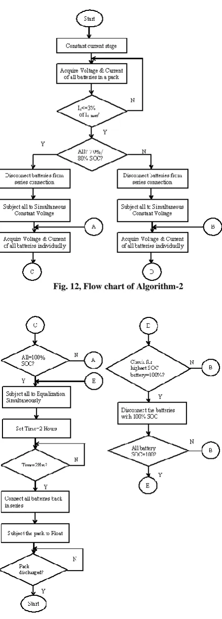
Algorithms developed on the basis of these proposed concepts are shown in Fig. 11 and 12 in the form of flow charts
.
Fig. 11, Flow chart of Algorithm-1
[image:4.595.60.272.500.632.2]Fig. 12, Flow chart of Algorithm-2
Fig. 12, Flow chart of Algorithm-2.Cont’d
5.
SCHEME
OF
PROPOSED
BALANCING AND
EQUALIZATION
The proposed balancing and equalization scheme is realized using a microcontroller and other logic circuitries. The optically isolated relay circuitry (Set of 8 Relays) is developed to switch the connections between the batteries in accordance with the algorithm executed within the microcontroller. The battery pack (with four 6V, 4.5Ah batteries in series) is considered for the experiment. Therefore the voltage can reach up to the level of 28.8V and current up to 1A while balancing and equalizing. These signals with higher magnitude cannot be fed to the microcontroller directly. Since Microcontroller accepts only 5V level signals, it is necessary to incorporate the signal conditioning circuits for acquiring both charging voltage and current.
This signal conditioning circuit is realized by using an operational amplifier with voltage divider circuit to bring the sensed voltage to the 5V level such that the microcontroller is able to convert into corresponding digital value. On the other hand the charging current is sensed using the Hall Effect current sensor. The 10 bit analog to digital converter (ADC) is used to convert analog voltage and current to corresponding digital values. The charger selected for the work is of constant voltage and constant current (CV/CC) with rating of 0-30V, 0-10A. The scheme has a buck converter with adjustable output @ 3A to supply the necessary voltage and current to the individual batteries while balancing and equalizing.
Both the balancing and equalization algorithms detailed in previous section 4, are implemented in firmware and ported on to the microcontroller. Based on the selected type of battery pack, microcontroller executes the one of the algorithms accordingly. Microcontroller used in this work is 8 bit and has a 10 bit ADC which is a perfect match for the application. Scheme has a 16 x 2 character liquid crystal display to show the voltages and current of batteries during the experiment.
The schematic representation of the proposed balancing and equalization method is shown in Fig. 13.
When the batteries are connected in series, their voltages depend upon the status of the relays. From Fig. 13, the terminal voltage of the 1st battery in a pack with respect to the ground is given by VF1 which is equal to the terminal voltage of the entire pack. The voltage VF2 is the terminal voltage of the 2nd battery with respect to ground. The voltage VF2 is the
Fig. 13, Balancing and Equalization Scheme
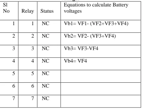
Table 1 Status of relays and equations to calculate battery voltages
Sl
No Relay Status
Equations to calculate Battery voltages
1 1 NC Vb1= VF1- (VF2+VF3+VF4)
2 2 NC Vb2= VF2- (VF3+VF4)
3 3 NC Vb3= VF3-VF4
4 4 NC Vb4= VF4
5 5 NC
6 6 NC
7 7 NC
When the batteries are disconnected from the series pack during balancing & equalization stage, the voltages Vb1, Vb2, Vb3 and Vb4 are equal to VF1, VF2, VF3, VF4. These are tabulated in Table-2.
Table 2 Status of relays and equations to calculate battery voltages
Sl
No Relay Status Battery voltages
1 1 NO Vb1= VF1
2
2 NO
Vb2= VF2
3
3 NO
Vb3= VF3
4
4 NO
Vb4= VF4
5
5
NC/NO
Depending on the battery
charge level either NC/NO
6
6
NC/NO
Depending on the battery
charge level either NC/NO
7
7
NC/NO
Depending on the battery
charge level either NC/NO
[image:6.595.49.287.426.608.2]6.
EXPERIMENTAL TEST SETUP
The experimental test set up shown in Fig. 14 consists of:
To validate the proposed work, four experiments were conducted and are explained in proceeding sections.
7.
RESULTS AND ANALYSIS
7.1. Basic 3 Step Charging –
(Experiment-1)
As indicated in the previous section this is the 1st experiment out of four of the proposed balancing and equalization method for batteries in a battery pack. The scope of this experiment is limited to determine the total number of hours that the battery pack of 24V, 4.5Ah (consisting of four 6V 4.5Ah batteries in series) would consume to charge to 100% SOC.
[image:7.595.57.298.69.268.2]Initially, the Lead acid battery bank consisting of 4 x 6 V, 4.5Ah (24V, 4.5Ah) is discharged to its 10% SOC before it is subjected to charging. The charging rate was C10. The 3 step, charging process, namely constant current, constant voltage and float charging method described in section 3 was adapted. Microcontroller was programmed to acquire the voltage and current at an interval of 1 hour. The acquired values of both voltage and current were displayed on LCD. The values displayed on the LCD are tabulated in Table 3.
Table 3, Battery pack voltage and time
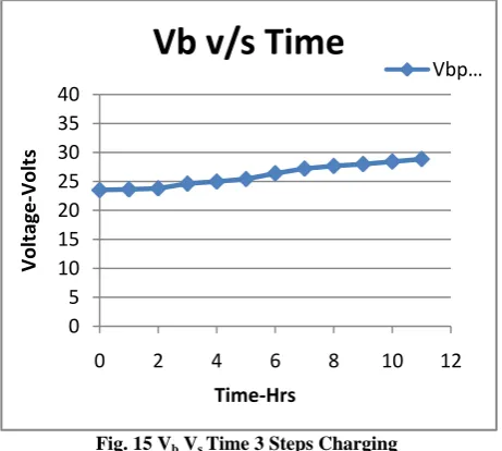
[image:7.595.315.546.495.702.2]The voltage Vbpack shown in Table 10 is the battery terminal voltage acquired at the end of every 1hour. The battery pack was charged to a maximum voltage of 28.8V (7.2v x 4) as per the recommendations in the datasheet. The battery with nominal voltage 24V is said to be fully charged when its terminal voltage reaches to 28.8V while charging and at the same time the charging current would have been less than 3% of its maximum charging current. The time noted from this experiment is taken as the reference to know the time required for balancing and equalizing the batteries in a battery pack. The values displayed on LCD are plotted on graph shown in Fig.-15.
Fig. 15 Vb Vs Time 3 Steps Charging
From the graph it should be noted that the battery voltage rises linearly. The total time taken by the battery to reach its full charge is about 11hours.
0
5
10
15
20
25
30
35
40
0
2
4
6
8
10
12
Voltage
-Volts
Time-Hrs
Vb v/s Time
Vbp…
Time Hr Vbpack V
0 23.51
1 23.62
2 23.79
3 24.61
4 24.98
5 25.41
6 26.39
7 27.21
8 27.66
9 27.99
10 28.42
11 28.84
1
2
4 3
5
6
8
7
i. 6V, 4.5Ah x 4 batteries connected in series to form 24V battery pack.
ii. Current sensor module to measure the current drawn by the battery pack while charging. iii. Charging voltage switching module with solid
state devices.
iv. Signal conditioning circuit to measure open/terminal voltages of each battery.
v. Push button key pad to select options while system is being used.
vi. Microcontroller board with LCD to show the messages and control.
vii. Power regulator to derive relay switch voltage. viii. Relay board used to connect the batteries in series
7.2. 4-Step Charging (Proposed Method-1)
(Experiment-2)
In the previous experiment the time required for the 24V battery to charge to its 100% SOC was determined. The time taken by the battery pack to reach its 100% SOC was approximately 11hrs. However it may vary depending on the charging current and the SOC% of the battery at the time of starting the charging. Now the purpose of the experiment 2 is to validate the proposed four step method of balancing and equalization by applying it to the battery pack.
The main objectives of this method are to save power and time while balancing and equalizing the batteries/cells in a battery pack. This is due to the fact that the existing methods do waste energy by dissipation, and takes more time while transferring energy from one cell to another. At the beginning of the experiment the battery pack was at 10% of its SOC. Then the pack was subjected to a proposed four step balancing and equalization method, which consists of constant current (Bulk Charging), balancing, equalizing and float steps. In this experiment algorithm-1 is used.
The initial charging current of the charger was adjusted to C/10 rate as per the recommendations. The terminal voltage of the battery pack, the charging current are monitored and recorded by the microcontroller during the experiment. The values were acquired by microcontroller at a regular interval of 1 hour. At the end of the 5th hour the current started decreasing drastically indicating the end of constant current step. At this point of a time the battery bank was at its 80% SOC. The battery pack voltage measured using multimeter was 25.2 whereas the value displayed on the LCD was 24.98V.
At the end of the constant current step, microcontroller acquires the voltages of all batteries in a pack by disconnecting them from series connection. The batteries connected and disconnected through an optically isolated relays. These relays are under the control of microcontroller and are operated according to the algorithm under execution. Further microcontroller switches to balancing mode of operation and connects all the batteries accordingly through the respective relay operation. The auxiliary charger designed based on the buck converter is used to balance all the batteries simultaneously. The microcontroller keeps monitoring the terminal voltages of all the batteries and displays them on LCD periodically till the end of balancing step. The step has almost taken 6hrs to complete. At the end of this step all the batteries were charged and balanced to 7.2V.
[image:8.595.319.565.83.340.2]On completion of balancing step, microcontroller switches to equalization process and continues for 2 hrs. During this step also all the batteries are simultaneously subjected to equalization i.e individually they are all equalized. At the end of the equalization period the batteries were at 7.4V each. Then the batteries are connected back in series to form the battery pack of nominal voltage of 24V. Further, the battery pack was switched to float mode by the controller to avoid the self-discharge. The charger voltage was lowered to 26.4V during float step as per the recommendations. The measured values of voltages based on time were displayed on LCD and tabulated in Table 4.
Table 4, Battery pack and individual battery voltages
From 6th hr to the end of 13 hr the batteries were individually subjected to balancing and equalization process.
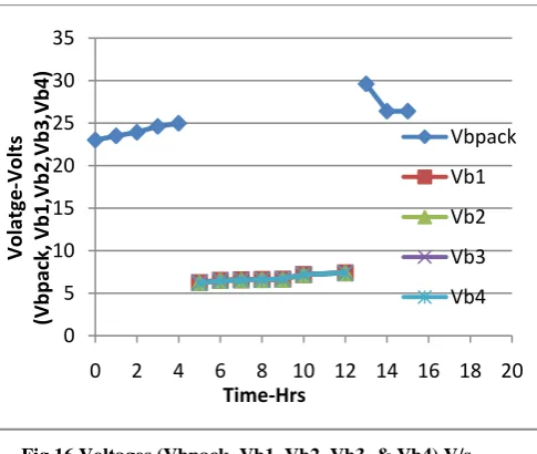
[image:8.595.317.560.395.600.2]The battery pack voltage verses time, and individual battery voltages verses time are plotted on graph shown in Fig.-16.
Fig.16 Voltages (Vbpack, Vb1, Vb2, Vb3, & Vb4) V/s Time
As indicated in the Fig.-16, the battery pack reached its 80% charge level during bulk charging, which lasted for about 4 hours. Next the batteries are subjected to constant voltage charging and balanced on reaching their maximum charge level. This phase lasted for about 6 hours. Further, the batteries are subjected to equalization for 2 hours i.e. controlled over charging. Later the batteries are switched to series configuration and subjected to float charging. All the batteries are subjected balancing & equalization process simultaneously. The total time taken for this experiment with 4 step proposed method is about 12 hours.
0
5
10
15
20
25
30
35
0
2
4
6
8
10 12 14 16 18 20
Volatge
-Volts
(Vb
pack,
Vb
1,V
b2
,Vb
3,Vb4
)
Time-Hrs
Vbpack
Vb1
Vb2
Vb3
Vb4
Sl No Time Hr Vbpack Volt Vb1 Volt Vb2 Volt Vb3 Volt Vb4 Volt1 0 23.01
Battery pack charging till it reaches the 80% level, Multimeter shows the 80% value to be 25.2V whereas microcontroller acquired value is 24.98V. 2 1 23.49
3 2 23.92
4 3 24.61
5 4 24.98
6 5
***
6.24 6.25 6.25 6.2
7 6 6.52 6.53 6.52 6.45
8 7 6.58 6.58 6.58 6.53
9 8 6.63 6.6 6.59 6.6
10 9 6.66 6.64 6.66 6.69
11 10 7.2 7.2 7.2 7.2
12 12 7.4 7.4 7.4 7.4
13 13 29.6 Battery pack voltage after equalization
14 14 26.4 Float voltage applied after equalization 15
7.3. 4-Step Charging (Proposed Method-1)
(Experiment-3)
The experiment-2 described in section 7.2 was conducted with an assumption that the all the batteries/cells in a pack would reach to their 80% SOC level at the end of bulk charging step and hence algorithm 1 was used. This experiment-3 is similar to experiment-2 except that the individual battery voltages are recorded during bulk charging process. However, the purpose of this experiment is to confirm:
[image:9.595.313.551.69.353.2]The procedure followed during this experiment was same as that of experiment 2 described in previous section 7.2. The acquired values are tabulated in Table 5.
Table 5. Battery pack and individual battery voltages (Experiment-3)
From 6th hr to the end of 13 hr the batteries were individually subjected to balancing and equalization process
[image:9.595.34.300.337.589.2]The battery pack voltage verses time, and individual battery voltages verses time are plotted on graph shown in Fig.-17.
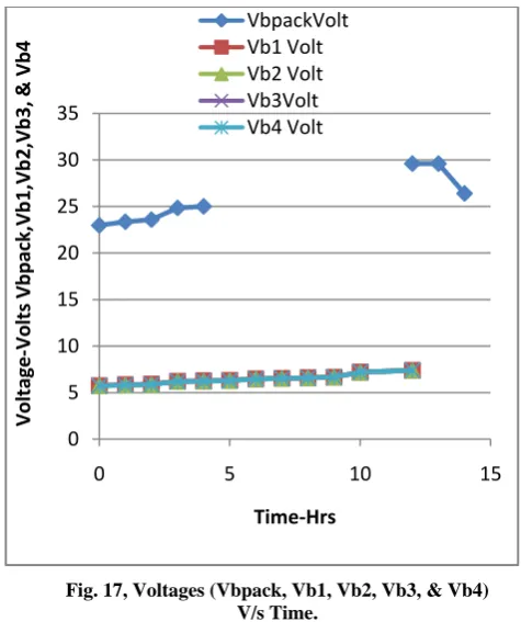
Fig. 17, Voltages (Vbpack, Vb1, Vb2, Vb3, & Vb4) V/s Time.
This experiment was conducted to understand the behaviour and the SoC of the individual batteries from the initial stage. It has been observed and noted that the SoCs of all the batteries are very close to each other.
7.4. 4-Step Charging (Proposed Method-1)
(Experiment-4)
Experiments described in sections 7.1.to 7.3 are to find the time required for charging the battery pack to its 100% of SOC, balance and equalize the batteries/cells and also to confirm the existence of difference in their SOCs. These experiments were carried out on a battery pack having normal charge level difference among the batteries/cells. But there could be a situation where in the batteries/cells of a battery pack may have large difference in their SOCs like 70%, 50%, 40% and 30% so on. To arrest such type of problem the algorithm-2 has been developed.
To validate the proposed algorithm-2, this experiment-4 was conducted to ensure equalization even when the batteries were at different SOCs. The other objective of the experiment is pave the way for identifying the weakest battery/cell if any of them are not improving in their SOC level. To create such a scenario, the batteries were discharged to 70%, 50%, 40% and 30% of their SOC level respectively before subjecting them to balancing & equalization. The algorithm steps detailed in section 4 were followed during this experiment. The readings of the experiments are tabulated in Table 6.
0
5
10
15
20
25
30
35
0
5
10
15
Voltage
-Volts
Vb
pack,Vb1
,Vb
2
,Vb3,
& Vb4
Time-Hrs
VbpackVolt
Vb1 Volt
Vb2 Volt
Vb3Volt
Vb4 Volt
Sl No
Time Hr
Vbpack Volt
Vb1 Volt
Vb2 Volt
Vb3 Volt
Vb4 Volt
Remark
1 0 22.98 5.75 5.74 5.76 5.73 Bulk Charging
2 1 23.36 5.86 5.83 5.85 5.82
3 2 23.59 5.92 5.89 5.90 5.88
4 3 24.84 6.23 6.21 6.21 6.19
5 4 25.01 6.28 6.25 6.25 6.23
6 5
***
6.32 6.30 6.31 6.29 Balancing
7 6 6.48 6.49 6.48 6.45
8 7 6.54 6.54 6.53 6.53
9 8 6.61 6.6 6.59 6.61
10 9 6.66 6.67 6.66 6.68
11 10 7.21 7.20 7.22 7.2
12 12 7.4 7.4 7.4 7.4
Equalizati on
13 13 29.6
Battery pack voltage after equalization
14 14 26.4
Float voltage applied after equalization
i. Firstly, to find any difference among the battery voltages i.e to find the difference in SOC among batteries, during bulk charging of battery pack. ii. Secondly if there is a difference do they reach
common value at the end of bulk charging step i.e when the pack is at 80% of SOC.
Table 6 Battery pack and individual battery voltages (Exceptional Case)
From 7th hr to the end of 13 hr the batteries were individually subjected to balancing and equalization process.
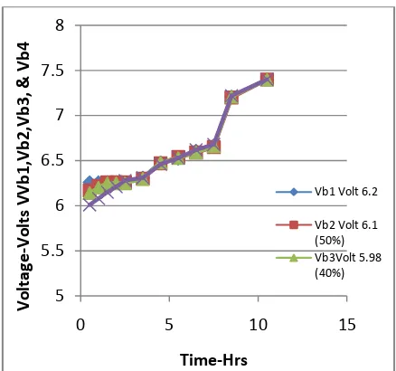
[image:10.595.34.306.100.365.2]During this experiment, battery pack consisting of four batteries with varied individual SOCs is subjected to balancing & equalization with algorithm-2. The process is continuously monitored and controlled by the microcontroller. Microcontroller ends the constant current step when the 1st battery with highest 70% SOC reached to 80% level as described in the algorithm-2. Next, the system disconnects all the batteries and puts them individually to bulk charging again and now they are powered from auxiliary supply till the charging currents of all reduces to less than 3% of maximum charging current. This is indicated by serial number 3-6 in Table-6. This step is also named as bulk charging as the batteries draws more current due to their lower SOCs. Next, all the batteries were subjected to balancing and equalization and are indicated by serial numbers (7-13) in Table-6. The outcome this experiment is that the battery pack consisting of four batteries varied SOCs can also be balanced and equalized without wasting energy and time. Another advantage of this method is that the weakest battery can be easily identified by way continuous monitoring of its SOC. If there is no improvement on the SOC of the weakest battery/cell and recommendation can be made to replace the battery/cell in the pack. Thus the burden on the stronger battery can be eased and also the health of the battery pack can be maintained within safe operating area with extended life. The battery pack voltage verses time, and individual battery voltages verses time are plotted on graph shown in Fig.-18.
Fig. 18 Voltages (Vb1, Vb2, Vb3, & Vb4) V/s Time (Algorithm-2)
8.
CONCLUSION
In this paper a unique non dissipative 4 steps balancing and equalizing process for Lead acid batteries and a unique three step balancing and equalization process for other battery types have been presented. Two unique algorithms have been devised to balance and equalize the batteries. The algorithm 2 has been devised and validated for the batteries having abnormal variations in their state of charge. These methods have been compared with the information gathered through literature survey and have following advantages over the existing methods of balancing and equalizing.
The proposed unique three step technique can be safely applied to other types of battery banks in future due to its simplicity and ease of implementation. Further, these techniques may be extended to battery management of all electric vehicles and hybrid electric vehicles.
5
5.5
6
6.5
7
7.5
8
0
5
10
15
Voltage
-Volts
VV
b1
,Vb
2,V
b3,
& Vb4
Time-Hrs
Vb1 Volt 6.2
Vb2 Volt 6.1 (50%) Vb3Volt 5.98 (40%) Sl No Time Hr Vbpack Volt Vb1 Volt Vb2 Volt Vb3 Volt Vb4 Volt Remark
1 0
24.18(50% SOC) 6.20 (70%) 6.1 (50%) 5.98 (40% ) 5.9 (30% ) Bulk Charging Battery Bank
2 0.5
24.58(<70 %)
6.26
(80%) 6.17 6.14 6.01
3 1 23.59 - 6.22 6.20 6.08 Bulk Charging Batteries 4 1.5 24.84 - 6.26 6.25 6.15
5 2 25.01 - - - 6.21
6 2.5
***
- - - 6.28
7 3.5 6.31 6.30 6.30 6.31
Balancing (Constant voltage) 8 4.5 6.48 6.47 6.48 6.46
9 5.5 6.52 6.54 6.53 6.53
10 6.5 6.61 6.59 6.59 6.62
11 7.5 6.67 6.65 6.66 6.68
12 8.5 7.21 7.20 7.21 7.22
13 10.5 7.4 7.4 7.4 7.4
Equalizatio n
14 29.6 Battery pack voltage after equalization
15 26.4 Float voltage applied after equalization
i. Accelerates the balancing & equalization process of batteries as the process is initiated at the end of constant current step.
ii. There is no loss of energy due to nonexistence of passive elements in the circuitry.
iii. There are no active elements to balance and equalize the batteries and hence the time required is small.
iv. Since no active elements in the system no transfer of energy and no loss.
v. No complex and specialized circuitry requirement. vi. There is a possibility of identifying the weakest battery in a pack as the continuous monitoring of their charge levels.
9.
REFERENCES
[1] Nasser H. Kutkut, Deepak .M.Divan, D.W.Novotny, “ Charge Equalization for Series Connected Battery Strings”, IEEE Transactions on Industry Applications, Vol 31, No.3 January 1995.
[2] Eklas Hossain, Ron Perez, Ramazan Bayindir, “ Implementation of Hybrid Energy Storage Systems to Compensate Microgrid Instability in the Presence of Constant Power Loads”, International Journal Of Renewable Energy Research, IJRER Vol.7, No.2, 2017 [3] Savvas Tsotoulidis, Athanasios Safacas, “Analysis of a
Drive System in a Fuel Cell and Battery powered Electric Vehicle”,International Journal Of Renewable Energy Research, IJRER Vol.1, No3, pp.31-42 ,2011. [4] Lekhchine Salima, Bahi Tahar, Soufi Youcef,
“Comparative Performances Study of a Variable Speed Electrical Drive”, International Journal Of Renewable Energy Research, IJRER Vol.2, No.4, 2012
[5] Rahim Ajabi-Farshbaf, Mohammad Reza Azizian, Sirvan Shazdeh, Ataollah Mokhberdoran, “Modeling of a New Configuration for DFIGs Using T-type Converters and a Predictive Control Strategy in Wind Energy Conversion Systems”, International Journal Of Renewable Energy Research, IJRER Vol.6, No.3, 2016
[6] Technical note, “Equalising Batteries”, Smart Power choices, Freedom and link 512-0027-0-01-Rev1. [7] Yuang-Shung Lee,and Ming-Wang Cheng, “Intelligent
Control Battery Equalization for Series Connected Lithium-Ion Battery Strings”, IEEE transactions on industrial electronics, vol. 52, no. 5, october 2005. [8] Dorin CADAR, Dorin PETREUS, Toma Patarau,
Niculaie Palaghita, “Active Balancing method for Battery Cell Equalization”, Acta Technica Napocensis Electronics and Telecommunication, Volume 51, number 2, 2010.
[9] Mohamed Daowd, Noshin Omar, Peter Van Den Bossche, Joeri Van Mierlo, “A Review of Passive and Active Battery Balancing based on MATLAB/Simulink”, International Review of Electrical Engineering (I.R.E.E.), Vol. xx, n. x Manuscript received Copyright © 2011 Praise Worthy Prize S.r.1.
[10] Mohamed Daowd, Mailier Antoine, Noshin Omar, Philippe and Joeri Van Mierlo, “ Battery Management System- Balancing Modularization Based on a Single Switched Capacitor and Bi-Directional DC/DC Converter with the Auxiliary Battery” Energies 2014, 7, 2897-2937; 10.3390/en7052897.
[11] Nasser H. Kutkut, H.L.N. Wiegman, Deepak .M.Divan, D.W.Novotny, “ Charge Equalization for an Electric Vehicle Battery System”, IEEE Transactions on Aerospace and Electronic Systems Vol 34, No.1 January 1998.
[12] Yunlong Shang, Chenghui Zhang, Naxin Cui, and Josep M. Guerrero, “A Cell-to-Cell Battery Equalizer With Zero-Current Switching and Zero-Voltage Gap Based on
Quasi-Resonant LC Converter and Boost Converter”, I E E E Transactions on Power Electronics 10.1109/TPEL.2014.2345672, 2015.
[13] J.F. Reynaud, C. E. Carrejo, O. Gantet, P. Aloïsi, B. Estibals, C. Alonso Wen-Yeau Chang, “Active balancing circuit for advanced lithium-ion batteries used in photovoltaic application” International Conference on Renewable Energies and Power Quality (ICREPQ’11) Las Palmas de Gran Canaria (Spain), 13th to 15th April, 201, RE&PQJ, Vol.1, No.9, May 2011
[14] Zhiwei He, Mingyu Gao , Caisheng Wang , Leyi Wang and Yuanyuan Liu, “Adaptive State of Charge Estimation for Li-Ion Batteries Based on an Unscented Kalman Filter with an Enhanced Battery Model Energies 2013, 6, 4134-4151; doi:10.3390/en6084134, ISSN 1996-1073.
[15] A. Lohner, E. Karden, R. W. DeDoncker,. “Charge equalizing and lifetime increasing with a new charging method for VRLA batteries”, In Proc. IEEE Int. l. Telecommunications Energy Conf., 1997, pp. 407-411. [16] Mohamed Daowd, Noshin Omar, Bavo Verbrugge, Peter
Van Den Bossche, Joeri Van Mierlo, “Battery Models Parameter Estimation based on Matlab/Simulink”, The 25th World Battery, Hybrid and Fuel Cell Electric Vehicle Symposium & Exhibition, ©EVS-25 Shenzhen, China, Nov. 5-9, 2010
[17] Mohamed Daowd, Mailier Antoine, Noshin Omar , Peter van den Bossche and Joeri van Mierlo, “Single Switched Capacitor Battery Balancing System Enhancements”, energies ISSN 1996-1073, Energies 2013, 6, 2149-2174; doi: 10.3390/en6042149.
[18] Taesic Kim, Wei Qiao, Liyan Qu, “A Multicell Battery System Design for Electric and Plug-in Hybrid Electric Vehicles”, 2012 IEEE International Electric Vehicle Conference (IEVC) Digital Object Identifier: 10.1109/IEVC.2012.6183240.
[19] William Gerard Hurley, Yuk Sum Wong, and Werner Hugo Wölfle, “Self-Equalization of Cell Voltages to Prolong the Life of VRLA Batteries in Standby Applications”, IEEE transactions on industrial electronics, vol. 56, no. 6, june 2009
[20] A. Tsapras, C. Balas, K. Kalaitzakis, and Dr. Eng. J. Chatzakis, “A New Equalization Scheme for Series Connected Battery Cells,” EPE Journal × Vol. 19 × no 3 × September 2009.
[21] Philip T. Krein, Robert Balog, “Life Extension Through Charge Equalization of Lead-Acid Batteries,” INTELEC 2002 Paper 32.1.
[22] Yee Wan Wong, et al, “A New State of Charge Estimation Method for Valve regulated Lead Acid Batteries”, Journal of EngineeringScience and Technology Vol,XX, No Y (Year) PPP-QQQ.
![Fig.8. Charge stages of a battery [22].](https://thumb-us.123doks.com/thumbv2/123dok_us/9296339.427202/3.595.57.280.76.227/fig-charge-stages-battery.webp)