ScienceDirect
Journal of Electrical Systems and Information Technology xxx (2016) xxx–xxx
Switching losses minimization by using direct torque control of
induction motor
Suraj Karpe
∗, Sanjay A. Deokar, Arati M. Dixit
Department of Technology, SPPU, IndiaReceived 15 June 2015; received in revised form 10 July 2016; accepted 15 August 2016
Abstract
Direct torque control is becoming the industrial standards for induction motor torque control. This paper presents switching loss minimization technique of improved direct torque control (DTC) of induction motor. Direct torque control (DTC) of an induction motor supplied by a voltage source inverter is a simple scheme that does not need long computation time, can be implanted without speed sensors and is insensitive to parameter variations. In principle, the motor terminal voltages and currents are used to estimate the motorflux and torque. Based on the instantaneous errors in torque and statorflux magnitude and estimates of theflux position, a voltage vector is selected to limit theflux and torque errors within theirflux and torque hysteresis bands. In the conventional DTC, the selected voltage vector applies for the whole switching period, irrespective of the magnitude of the torque error. DTC drive gives variable switching frequency and high torque ripple. DTC gives torque andflux ripples because no any VSI states are capable to generate the exact voltage vector from switching table required to make zero both the torque electromagnetic error and the statorflux error. To minimize this problem, a torque hysteresis band with variable amplitude fuzzy logic controller is proposed. The fuzzy logic controller is used to reduce theflux and torque ripples and it improves performance DTC especially at low speed. A duty ratio control scheme for an inverter-fed induction machine using DTC method is presented in this article. The use of the duty ratio control gives improved steady state torque response, with less torque ripple than the conventional DTC. Fuzzy logic control (FLC) used to implement the duty ratio controller. Total harmonic distortion (THD) calculation of electromagnetic torque, rotor speed and stator current of DTC and DTC with fuzzy has done successfully in this article. With the help of FLC with duty ratio, 8% THD in torque, speed and stator current have minimized compared with DTC (Uddin and Hafeez, 2012). In this paper, switching loses minimization technique through THD minimization. Switching losses are minimized because the transistors are only switched when it is needed to keep torque andflux within their hysteresis bounds, improve efficiency & reduced losses. Direct torque control with the fuzzy logic controller has verified by MATLAB SIMULINK and experimentally.
© 2016 Electronics Research Institute (ERI). Production and hosting by Elsevier B.V. This is an open access article under the CC BY-NC-ND license (http://creativecommons.org/licenses/by-nc-nd/4.0/).
Keywords: Direct torque control; Induction motor; Fuzzy logic; Torque ripple minimization; Fuzzy logic controller
∗Corresponding author.
E-mail addresses:[email protected],karpe [email protected](S. Karpe). Peer review under the responsibility of Electronics Research Institute (ERI).
http://dx.doi.org/10.1016/j.jesit.2016.08.007
2314-7172/© 2016 Electronics Research Institute (ERI). Production and hosting by Elsevier B.V. This is an open access article under the CC BY-NC-ND license (http://creativecommons.org/licenses/by-nc-nd/4.0/).
1. Introduction
The machine can be driven at variable speed, with variable frequency, sinusoidal voltage. In power electronics, inverter gives such voltage by switching. The inverter may generate a considerable amount of voltage & current harmonics. These harmonics causes additional power losses in motor winding & magnetic core, which reduces the life of the motor. Distorted current waveform also gives rise to torque pulsation, and may damage to shaft, coupling & other mechanical component. By increasing switching frequency, total harmonic distortion (THD) of motor current & torque reduces. Switching losses in inverter gives amount of power losses in drives. Switching losses minimization reduces the manufacturing & maintenance cost of drives inTakahashi and Nouguchi (1986).
Direct torque control (DTC) has been actively investigated during the last decade in the area of AC drives for induction motors. This control strategy wasfirst introduced by Takahashi in 1986 (Takahashi and Nouguchi, 1986) and at the same time Depenbrock developed in 1988 under the name of direct self control (Tang et al., 2003). Nevertheless, just one major manufacturer has an industrial application based on DTC, which was launched in 1995 (Lai and Lin, 2003). The main advantage of DTC is the high performance achieved (decoupled control statorflux and torque, fast torque response and robustness) together with the simplicity of the scheme (coordinate transformation, modulation block and current regulation block not require). Traditionally, the standard voltage source inverter (VSI) used in AC drives is composed of two switches per leg, where the load can be connected either to the upper or lower line of the DC-link. This is known as a two-level VSI. However, fast semiconductors have a limitation in the maximum voltage that can be handled. Series connection is necessary for high power and voltage applications, and therefore a voltage balance is required. Moreover, very high dV/dt is generated leading to important electromagnetic interference (EMI) and high windings insulation stress. Multilevel inverters are an emerging technology that can overcome the limitations associated with the standard low cost two-level VSI (Lai and Lin, 2003). DTC drive becomes one of the possible alternatives to the well-known vector control of Induction Machines over the last decade. Its main characteristic is it gives good performance, obtaining results has more accuracy as good as compare with classical but with several advantages based on its simpler control diagram. DTC (direct torque control) is characterized, as deduced from the name, by directly controlledflux and torque means indirectly controlled stator voltage and current. The DTC has some advantages comparison with the conventional vector-controlled drives, like approximately sinusoidal stator currents and statorfluxes, high dynamic performance even at locked rotor and standstill, Absences of co-ordinates transform, absences of mechanical transducers, current regulators, PWM pulse generation, PI control offlux and torque and co-ordinate transformation are not required, very simple control scheme and low computation time, reduced parameters sensitivity, superior dynamic properties. Conventional DTC has also some pitfall are possible problems during starting and low speed operation, variable switching frequency; these are disadvantages that we want to remove by using fuzzy logic controller. In the following, we will describe the application of fuzzy logic in DTC control (Kang and Sul, 1999; Rumzi et al., 2004; Abdalla, 2005).
Two different control methods are designed in this paper. Thefirst is based on the conventional DTC scheme adapted for a two level inverter. The second is based on a fuzzy logic controller used to replace the conventional table used in DTC for the inverter state selection. A direct torque control (DTC) is a simplified variation offield orientation was developed by Takahashi (Kang and Sul, 1999) and Depenbrock (Tang et al., 2003).Fig. 1shows a DTC of an induction motor. In DTC drives, with the help of selection of an optimum inverter switching state, it is possible to control directly the statorflux linkage and the electromagnetic torque. Switching state is used to regulate theflux and the torque errors within their respective hysteresis bands and to obtain the fastest torque response and highest efficiency at every instant. DTC is more straightforward thanfield-oriented control and less dependent on the motor model, since the stator resistance value is the only machine parameter used to estimate the statorflux. High torque ripple is one of the disadvantages of DTC given inKang et al. (2005). Under constant load in steady state, an active switching state originate the torque to continue to increase past its reference value until the end of the switching period; then a zero voltage vector is applied for the next switching period causing the torque to continue to decrease below its reference value until the end of the switching period. A possible solution to reduce the torque ripple is to use a high switching frequency; however, that requires expensive processors and switching devices. A less expensive solution is to use fuzzy logic duty ratio controller. In DTC with duty ratio control, the selected voltage vector is applied for a part of the switching period rather than the complete switching period as in conventional DTC.
By applying a nonzero voltage vector for only a portion of the switching period, and the effective switching frequency is doubled for the remainder of the period of zero voltage vector. Therefore, the torque variations between below and above the average value are smaller for any single switching period. Further, because the duty ratio is controlled, the average stator voltage is adjusted directly. There is no need to make course corrections by the use of multiple switching periods with a nonzero voltage vector or a whole switching period with a zero voltage vector. The average phase voltage is adjusted more smoothly, and the overall torque ripple is reduced. In this paper, THD calculation done successfully. With the help of FLC with duty ratio, 8% THD in torque, speed and stator current have minimized compared with DTC (Uddin and Hafeez, 2012). Hear switching losees minimization technique through THD minimization. Switching losses are minimized because the transistors are only switched when it is needed to keep torque andflux within their hysteresis bounds, improve efficiency & reduced losses. The use of a duty ratio fuzzy controller is proposed inHazzab et al. (2007). The theme of this article is to verify by simulation and experimentally that a DTC with a duty ratio fuzzy controller reduces the torque ripple compared to conventional DTC.
2. DTC schematic
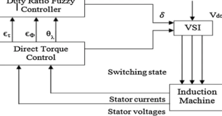
DTC scheme is given inFig. 1, theФandτsignals are delivered to two hysteresis comparators. The corresponding
digitized output variables: change of magneticfluxΔФ, mechanical torqueΔτand the statorflux position sectors SN
created a digital word, which selects the suitable voltage vector from the switchingTable 1. The selection generates pulse Sa, Sb, Scto control the power switches in the inverter. Three-level torque and two levelflux hysteresis controllers
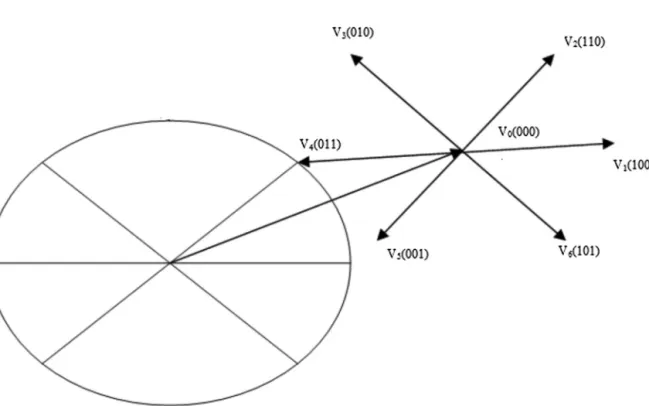
are used according to the outputs of the torque controller and the sector information of suitable voltage vectors for both the inverters are selected from a switching table as it is shown inFig. 2(Lee, 1990).Fig. 2shows the voltage
Fig. 1. Block diagram of DTC scheme. Table 1
Classical DTC switching table.
Flux Torque Sector Sϕ
Δϕ Δτ Sϕ1 Sϕ2 Sϕ3 Sϕ4 Sϕ5 Sϕ6 1 1 V2 V3 V4 V5 V6 V1 1 0 V7 V0 V7 V0 V7 V0 1 −1 V6 V1 V2 V3 V4 V5 −1 1 V3 V4 V5 V6 V1 V2 −1 0 V0 V7 V0 V7 V0 V7 −1 −1 V5 V6 V1 V2 V3 V4
Fig. 2. Eight possible voltage space vectors.
Fig. 3. Statorflux vector.
vectors which usually engage in DTC scheme when the statorflux vector is lying sector I which is shown inFig. 3. The selection of a voltage vector at each cycle period is used to maintain the torque and the statorflux within the limits of two hysteresis bands. A quick torque response to be achieved, but the steady state performance gives undesirable ripple in current,flux and torque, mainly due to the absence of information about torque and rotor speed values in the voltage selection algorithm (Toufouti et al., 2006; Halleh et al., 2008).
3. Modeling of IM for DTC
3.1. Concordia transformation for voltages
By using this transformation, two voltages Vsdand Vsqare obtained from the measured voltage U0.
Vsd = 2 3U0 Sa− 1 2(Sb+Sc) (1) Vsq= 1 √ 2U0(Sb−Sc) (2)
whereU0stands for DC link inverter voltage,VsdandVsqare the real and imaginary components of the stator voltage
vector.
3.2. Concordia transformation for currents
This transformation is used to obtain currents Isd, and Isq, from the Isa, Isband Iscof the stator currents.
Isd = 3 2Isa (3) Isq= 1 √ 2(Isb−Isc) (4)
whereIsdandIsqare the direct and quadrature components of the stator current respectively.
3.3. Flux and torque estimations
DTC command is based on estimation influx and in torque. In order to realize these estimates, we used the results of Concordia transformations as given inOrost et al. (2007).
Because stator voltage is defined by: Vs =Rs∗Is+ dϕs dt (5) whereVsandIsare the stator voltage and stator current,Rsis stator resistance respectively
That is why, we have two equations: Φsd = t 0 (Vsd−RsIsd)dt (6) Φsq = t 0 Vsq−RsIsq dt (7)
whereΦsdandΦsqare d-axis and q-axis component of statorflux linkage respectively.
Now estimated torque is calculated as, τe=p
ΦsdIsq−ΦsqIsd (8)
4. DTC controller
The state of the voltage source inverter is used to impose the required statorflux. The stator voltage impresses directly the statorflux by neglecting the ohmic drops in accordance with the following equation:
d
Fig. 4. Block diagram for DTC with a duty ratio fuzzy controller.
or
Δψs =u¯sΔt (10)
where d
dtψ¯srepresents the change in statorflux caused by the application of an inverterVs.
Decoupled control of the statorflux modulus and torque is achieved by the radial and tangential components of the statorflux-linkage space vector respectively. These two components are directly proportional to the components of the corresponding voltage space vector in the same directions. The hysteresis band has to be set large enough to limit the inverter switching frequency below a certain level that is usually determined by thermal restriction of power devices. Since the hysteresis bands are set to cope with the worst locus case, the system performance is inevitably degraded in a certain operating range, especially in a low speed region. In torque hysteresis controller, an elapsing time to move from lower to upper limit, and vice versa can be changed according to operating condition (Tang et al., 2003; Lai and Lin, 2003; Rumzi et al., 2004).
5. Fuzzy logic controller
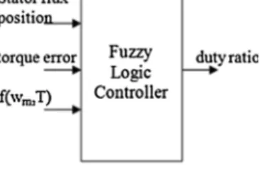
The fuzzy logic controller consists of four major blocks: knowledge base, fuzzification, inference mechanism, and defuzzification. The knowledge base is composed of a database and a rule base. The database contains input and output membership functions. The rule base is made up of a set of linguistic rules relating the fuzzy input variables to the desired fuzzy control actions. Fuzzification converts crisp input signals, the statorflux position and torque error and f(wm,T). The output of the fuzzy logic controller is the duty ratio (δ) (Lee, 1990; Lai and Lin, 2003; Orost et al.,
2007).
5.1. Duty ratio control
In the conventional DTC a voltage vector applies for the entire switching period, and this causes the stator current and electromagnetic torque to increase over the whole switching period. For small errors, the electromagnetic torque exceeds its reference value early during the switching period, and continues to increase, causing a high torque ripple. This is then followed by switching cycles in which the zero switching vectors are applied in order to reduce the electromagnetic torque to its reference value. The ripple in the torque andflux can be reduced by applying the selected inverter vector not for the entire switching period, as in the conventional DTC induction motor drive, but only for part of the switching period. The time for which a non-zero voltage vector has to be applied is chosen just to increase the electromagnetic torque to its reference value and the zero voltage vector is applied to the rest of the increase in the number of semiconductor switches in the inverter. During the application of the zero voltage vector no power is absorbed by the machine, and thus the electromagneticflux is almost constant; it only decreases slightly. Fig. 4 shows a DTC induction motor drive with a duty ratio fuzzy logic controller. The average input DC voltage to the motor during the application of each switching vector isδVdc. By varying the duty ratio between zero and one, it is possible to apply
Fig. 5. Fuzzy logic duty ratio estimator. Table 2
%THD calculation in DTC and in DTC fuzzy logic controller.
Type Torque (%THD) Speed (%THD) Stator current R-ph (%THD) Stator current
Y-ph (%THD)
Stator current B-ph (%THD)
DTC 62.28% 88.47% 86.52% 62.39% 60.82%
DTC with fuzzy 55.07% 75.70% 79.86% 45.79% 51.55%
will be less compared to applying the full DC link voltage for the complete switching period. This increases the choice of the voltage vector, without an increase in the number of semiconductor switches in the inverter (Fig. 5).
The duty ratio of each switching period is a non-linear function of the electromagnetic torque error, statorfl ux-linkage error, and the position of the stator flux-linkage space vector. Thus, it is difficult to model this nonlinear function. However, by using a fuzzy logic based DTC system, it is possible to perform fuzzy logic based duty ratio control, where the duty ratio is determined during every switching cycle. In such a fuzzy-logic system, there are three inputs, the statorflux position and torque error andf(wm,T). The output of the fuzzy logic controller is the duty ratio
(δ) (Aimer et al., 2009).
A better drive performance has been achieved by varying the duty ratio of the selected voltage vector during each switching period, according to the magnitude of the torque error and position of the statorflux. A duty ratio control scheme for a DTC method is presented here. The use of the duty ratio control gives improved steady state torque response, with less torque ripple than the conventional DTC. Fuzzy logic control is used to implement the duty ratio controller. With the help of FLC with duty ratio, 8% THD in torque, speed and stator current have minimize shown in
Table 2.
There are many types of fuzzy logic controller for this particular application. The inputs and the output of the fuzzy controller are assigning. Triangular membership functions as shown inFig. 6. The universe of discourse for the torque error and the duty ratio is adjusted using simulations to get an optimal torque ripple reduction.
The emphasis on the fuzzy rule is to reduce the torque ripple. Generally the duty ratio is proportional to the torque error, since the torque rate of change is proportional to the angle between the applied voltage vector and the stator
flux, also the duty ratio depends on theflux position within each sector. The duty ratio is selected proportional to the magnitude of the torque error, so if the torque error is small, medium or large then the duty ratio is small, medium or large respectively.
5.2. Switching losses
The losses in the semiconductors can be divided into two parts, namely switching losses (arising when the devices are switched on or off) and conduction losses (due to the ohmic resistance). These losses depend on the applied voltage, the commutated current and the semiconductor characteristics. Observing that in a VSI inverter, the voltage seen by each semiconductor is always half the total DC-link voltage leads to the ideal switch turn-on (energy) loss
Eon=eon
1
2Vdciph (11)
where eon is a coefficient and iph is the phase current. For the ideal switch, turn-off losses, a corresponding equation
results with the coefficient eoff. Typically, eoff is an order of magnitude larger than eon. For a diode, the switch-on
-0.02 -0.015 -0.01 -0.005 0 0.005 0.01 0.015 0.02 0 0.2 0.4 0.6 0.8 1 cilian Degree of membership N Z P -3 -2 -1 0 1 2 3 0 0.2 0.4 0.6 0.8 1 theta Degree of membership
the6 the7the8 the9 the10 the11 the0 the1 the2 the3 the4 the5
0 1 2 3 4 5 6 7 0 0.2 0.4 0.6 0.8 1 output1 Degree of membership s0 s1s2s3s4s5s6 s7 -2 -1.5 -1 -0.5 0 0.5 1 1.5 2 0 0.2 0.4 0.6 0.8 1 zhuanju Degree of membership NL NS ZE PS PL
(a)
(b)
(c)
(d)
Fig. 6. (a) Membership function for statorflux position. (b) Membership function of torque error. (c) Membership functions forf(wm,T). (d)
Membership functions for duty ratio (δ).
nonlinear in the commutated phase current. Similar to the switching losses, the conduction losses also depend on the applied voltage and the phase current. The DC link voltage is constant despite the neutral pointfluctuations. The phase current is the sum of the current ripple and the fundamental component, which in turn depends only on the operating point given by the torque and the speed, but not on the switching pattern. Since the ripple is small compared to the fundamental current (typically in the range of 10% for a 3-level inverter), the conduction losses can be considered to be independent of the switching pattern.
6. Simulation results
Conventional DTC and DTC with fuzzy logic controller for a 4-pole induction machine have simulated and com-pared. Constant torque andflux commands of 15 Nm and 0.9 Wb have used. The parameters for the induction motor are listed as below. The rating of induction motor is 5 HP, 440 V, 50 Hz, 1440 RPM star connected induction motor. For all simulations, the motor characteristics will be utilized as below:
Stator resistance (ohm) = 1.405 Rotor resistance (ohm) = 1.395 Stator self inductance (H) = 0.005839 Rotor self inductance (H) = 0.005839 Mutual inductance (H) = 0.2037 No. of poles = 4
Moment of inertia (kg m2) = 0.02
Load torque (Nm) = 15 Sampling time = 1 s
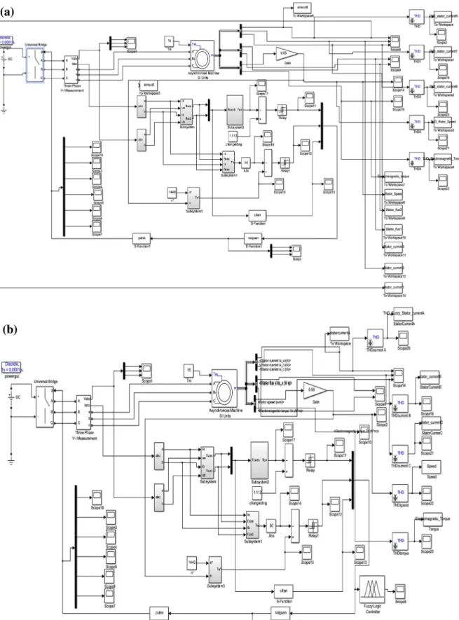
Fig. 7. (a) MATLAB, SIMULINK model of direct torque control of induction motor (b) MATLAB, SIMULINK model of direct torque control of induction motor with fuzzy logic controller.
The DTC controller that decides theflux sector and selects the switching vector simulated using MATLAB code
file. The MATLAB fuzzy logic controller used in the implementation of the duty ratio fuzzy controller. A Mamdani type fuzzy inference engine used in the simulation. The membership functions and the fuzzy rules are adjusted using the simulation until an optimal torque ripple reduction achieved. The SIMULINK model of conventional direct torque control for induction motor and with fuzzy logic controller are shown inFig. 7(a) and (b).Fig. 8(a) and (c) shows the torque response of the motor using conventional DTC and DTC with the duty ratio fuzzy control, respectively for a step torque command of 15 Nm with the drive output updated at a rate of 1 kHz.
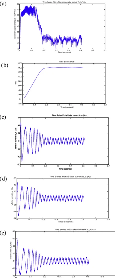
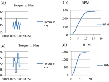
The torque reaches its steady state value in less than 20 ms in both controllers. The torque characteristic in DTT and DTC with fuzzy shown inFig. 12(a) and (c).Fig. 12(b) and (d) shows the rotor speed of induction motor with DTC and DTC with fuzzy logic controller. Figs.8(c)–(e) and9(c)–(e) show the stator current Ir, Iy, Ibof the motor using
conventional DTC and DTC with the fuzzy logic controller, respectively. There is a reduction in the stator current ripple when the duty ratio fuzzy control is used. Also in the case study, DTC with fuzzy logic controller reduces torque and
flux ripples and it improves performance DTC especially at low speed shown inFig. 7compared toUddin and Hafeez (2012). The future scope is to improve the performance by using predictive torque control method with multilevel inverter. If a multilevel inverter is applied, we can imagine that the PCC algorithm will greatly reduce the calculation time.
7. Case study
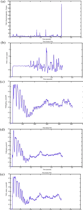
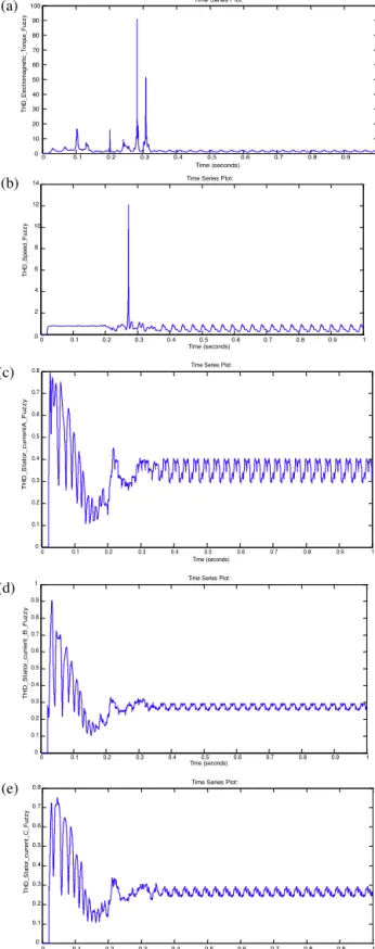
The proposed scheme shows better response as compared to the conventional one in terms of ripple in speed,torque and stator current during transient conditions.Fig. 12(a) and (c) presents the corresponding torque response of the two DTC schemes. It can be compared that, in the steady state, the torque ripple in the conventional scheme is approximately 6 Nm while, in the proposed scheme, it is only 4 Nm, which proves the superiority of the proposed DTC scheme over the conventional one compare toUddin and Hafeez (2012). Total harmonic distortion (THD) has calculated successfully in this article by using MATLAB 2013 compare toUddin and Hafeez (2012). Fuzzy logic control is used to implement the duty ratio controller. THD calculation of electromagnetic torque in the DTC SIMULINK model is shown inFig. 10(a) and THD calculation of electromagnetic torque in DTC with fuzzy is shown inFig. 11(a), also THD calculation of stator current IR, IY, IBin DTC and DTC with fuzzy is shown in Figs.10(c–e) and11(c–e). With the help of FLC
with duty ratio, 8% THD in torque, speed and stator current have minimized compared with DTC shown inTable 2
compared withUddin and Hafeez (2012).
8. Experimental setup and results
The DTC with the duty ratio fuzzy control has implemented using a setup consisting of a six step voltage inverter and TMS320F240 digital signal processor (DSP) that controlled and generated the switching commands for the inverter gate drive circuit (Figs. 13 and 14).
A 4-pole 5-HP induction machine that was a 1.405 stator resistance used in the implementation of conventional DTC control and the DTC with the duty ratio fuzzy control the switching frequency has set at 5 kHz. The controller reads the motor current every 200s and decides the stator voltage vector and the duty ratio. A torque and flux commands of 15 Nm and 0.9 Wb was used, the DC bus voltage was set at 440 V. Since no speed control loop was included in the DTC controller the motor speed was increasing rapidly. To provide a common reference to compare the performance of the conventional DTC and the DTC with the duty ratio fuzzy control the motor was loaded by either applying braking pressure against the motor shaft or locking the rotor while measuring the motor torque and terminal voltages and currents. In both loading methods the torque ripple was reduced when the duty ratio controller was used.
Fig. 15(a) and (b) shows the electromagnetic torque response using conventional DTC and DTC with the duty ratio fuzzy control respectively. The waveforms of the electric torque were obtained by using the 12 bit digital to analog converter (D/A) available on the DSP board to convert the calculated values of the torque to an equivalent analog signal that lies within the 0–5 V D/A converter range. The motor was loaded by applying braking pressure against the motor shaft. The torque ripple is 0.7 Nm with the conventional DTC while for DTC with the duty ratio fuzzy control the ripple is reduced to 0.4 Nm as compared with articleUddin and Hafeez (2012)with the use of the duty ratio control method. The experimental results are similar to the simulation results.
0 0.1 0.2 0.3 0.4 0.5 0.6 0.7 -200 0 200 400 600 800 1000 1200 1400 1600 Time (seconds) da ta
Time Series Plot:
0 0.1 0.2 0.3 0.4 0.5 0.6 0.7 0 10 20 30 40 50 60 70 80 Time (seconds) <E le c tr o m agne ti c t or que T e (N* m )>
Time Series Plot:<Electromagnetic torque Te (N*m)>
0 0.1 0.2 0.3 0.4 0.5 0.6 0.7 -60 -40 -20 0 20 40 60 Time (seconds) <S ta to r c u rre n t is _a (A )>
Time Series Plot:<Stator current is_a (A)>
0 0.1 0.2 0.3 0.4 0.5 0.6 0.7 -40 -20 0 20 40 60 80 Time (seconds) <S ta to r c urre nt is _b (A )>
Time Series Plot:<Stator current is_b (A)> 0 0.1 0.2 0.3 0.4 0.5 0.6 0.7 -60 -40 -20 0 20 40 60 Time (seconds) <S ta to r c urre nt is _a (A )>
Time Series Plot:<Stator current is_a (A)> -60 -40 -20 0 20 40 60 Time (seconds) <S ta to r c u rre n t is _a (A )>
Time Series Plot:<Stator current is_a (A)>
-60 -40 -20 0 20 40 60 Time (seconds) <S ta to r c u rre n t is _a (A )>
Time Series Plot:<Stator current is_a (A)>
(a)
(b)
(c)
(d)
(e)
Fig. 8. Torque, speed, Ir, Iy, Ibcharacteristic with DTC.
0 0.1 0.2 0.3 0.4 0.5 0.6 0.7 0.8 0.9 1 0 10 20 30 40 50 60 70 80 Time (seconds) <E le c tr o m agne ti c t or que T e (N* m )>
Time Series Plot:<Electromagnetic torque Te (N*m)>
0 0.1 0.2 0.3 0.4 0.5 0.6 0.7 0.8 0.9 1 -200 0 200 400 600 800 1000 1200 1400 1600 Time (seconds) ro to r_ s peed_ fu zz y
Time Series Plot:
0 0.1 0.2 0.3 0.4 0.5 0.6 0.7 0.8 0.9 1 -60 -40 -20 0 20 40 60 Time (seconds) <S ta to r c urre nt is _a (A )>
Time Series Plot:<Stator current is_a (A)>
0 0.1 0.2 0.3 0.4 0.5 0.6 0.7 0.8 0.9 1 -40 -30 -20 -10 0 10 20 30 40 50 60 Time (seconds) <S ta to r c u rr ent is _b (A )>
Time Series Plot:<Stator current is_b (A)>
0 0.1 0.2 0.3 0.4 0.5 0.6 0.7 0.8 0.9 1 -60 -40 -20 0 20 40 60 Time (seconds) <S ta to r c urre nt is _a (A )>
Time Series Plot:<Stator current is_a (A)> (a)
(b)
(e) (c)
(d)
Fig. 9. Torque, speed, Ir, Iy, Ibcharacteristics of DTC with fuzzy.
0 0.1 0.2 0.3 0.4 0.5 0.6 0.7 0 20 40 60 80 100 120 140 160 180 200 Time (seconds) T HD _E le c tr o m agne ti c _ T o rqu e
Time Series Plot:
0 0.1 0.2 0.3 0.4 0.5 0.6 0.7 0 0.5 1 1.5 2 2.5 Time (seconds) T HD i n r o to r s pee d
Time Series Plot:
0 1000 2000 3000 4000 5000 6000 0 0.1 0.2 0.3 0.4 0.5 0.6 0.7 0.8 TH Ds ta to rc u rre n tR 0 0.1 0.2 0.3 0.4 0.5 0.6 0.7 0 0.1 0.2 0.3 0.4 0.5 0.6 0.7 0.8 0.9 Time (seconds) TH Ds ta to rc u rre n tY
Time Series Plot:
0 0.1 0.2 0.3 0.4 0.5 0.6 0.7 0 0.1 0.2 0.3 0.4 0.5 0.6 0.7 0.8 Time (seconds) T HD _s ta to r_ c u rre n tB
Time Series Plot: (a)
(b)
(c)
(d)
(e)
Fig. 10. THD in torque, speed, Ir, Iy, Ibin DTC.
0 0.1 0.2 0.3 0.4 0.5 0.6 0.7 0.8 0.9 1 0 10 20 30 40 50 60 70 80 90 100 Time (seconds) T HD _E le c tr o m agne ti c _ T o rque_ Fu zz y
Time Series Plot:
0 0.1 0.2 0.3 0.4 0.5 0.6 0.7 0.8 0.9 1 0 2 4 6 8 10 12 14 Time (seconds) T HD _S peed_ Fu zz y
Time Series Plot:
0 0.1 0.2 0.3 0.4 0.5 0.6 0.7 0.8 0.9 1 0 0.1 0.2 0.3 0.4 0.5 0.6 0.7 0.8 Time (seconds) T HD _ S ta to r_ c u rre n tA _F uz z y
Time Series Plot:
0 0.1 0.2 0.3 0.4 0.5 0.6 0.7 0.8 0.9 1 0 0.1 0.2 0.3 0.4 0.5 0.6 0.7 0.8 0.9 1 Time (seconds) T HD _S ta to r_ c u rre n t_ B_ F u zz y
Time Series Plot:
0 0.1 0.2 0.3 0.4 0.5 0.6 0.7 0.8 0.9 1 0 0.1 0.2 0.3 0.4 0.5 0.6 0.7 0.8 Time (seconds) T HD _S ta to r_ c u rre n t_ C _ F u z z y
Time Series Plot: (a)
(b)
(c)
(d)
(e)
Fig. 11. THD in torque, speed, Ir, Iy, Ibin DTC with fuzzy.
(a) THD in speed in DTC with fuzzy. (b) THD in torque in DTC with fuzzy. (c) THD in IRDTC with fuzzy. (d) THD in IYin DTC with fuzzy. (e) THD in IBin DTCwith fuzzy.
(a) (b)
(c) (d)
Fig. 12. Case study of speed and torque in DTC and DTC with fuzzy.
(a) Torque in DTC model. (b) Speed in DTC model. (c) Torque in DTC model. (d) Torque in DTC model.
Fig. 13. Block diagram of the experimental setup.
Fig. 15(c) and (d) shows the stator phase current ia using conventional DTC and DTC with the duty ratio fuzzy
control respectively. The duty ratio control reduces the stator current harmonics which inturn reduces the torque ripple, the power losses, and increases efficiency of the drive. Similar results were obtained in simulation.Fig. 16shows the
flow chart for the controller (Gadoue et al., 2009; Youb and Craciunescu, 2009).
9. Conclusion
A novel FLC-based DTC scheme for IM drive has been presented in this paper. Direct torque control (DTC) is an optimized, simple induction motor drive control principle where inverter switching directly controls the motorflux and torque. It can be implemented without the use of speed andflux sensors, reducing the cost and eliminating the need for regular maintenance. It does not require any coordinate transformation, which would increase the computational burden. Another advantage of DTC over field-oriented control is that it depends only on the value of the stator resistance, so it is less sensitive to parameter value variations. The measured input values for the DTC control are the motor currents and voltages. The voltages can be defined from the DC-bus voltage and the inverter switch positions
Fig. 14. Photographical view of experimental setup.
without the use of sensors. The voltage and current signals are inputs to theflux and torque estimator, which produces the values of stator flux and torque at a specific switching period. Motor torque andflux hysteresis comparators compare the actual values to the reference values of the torque and theflux. The outputs from these comparators are updated every switching period and they indicate how the torque andflux have to be varied. Depending on the outputs from the comparators, the switching logic directly determines the optimum inverter voltage vector. The simplicity of the DTC method comes with some disadvantages, the main one being the high torque ripple. The main reason for the torque ripple in the conventional DTC is that the selected voltage vector applies for the complete switching period, regardless of the magnitude of the torque error, resulting in a wide torque hysteresis band. A better drive performance can be achieved by varying the duration of applying the selected voltage vector during each switching period, according to the magnitude of the torque error and the position of the statorflux, which will result in a small torque hysteresis band and hence less torque ripple. This article presented a DTC scheme with duty ratio control for inverter fed induction machines. In this method, the duty ratio is adjusted to minimize the torque ripple. Observation and analysis show that the suitable duty ratio depends on the magnitude of the torque error, the sign of the flux error, and the position of the statorflux. Since the relation between the mentioned variables is nonlinear and difficult to model mathematically, fuzzy logic is a suitable choice to use in the design of the duty ratio controller. From the observations obtained by examining the conventional DTC behavior, two sets of fuzzy rules were formulated: one when theflux magnitude is less than its reference value and the second when the flux magnitude is greater than the reference value. The inputs to each rule set are the magnitude of the torque error and the position of the stator flux; the output is the duty ratio. The universe of discourse of each input and output is divided into three membership functions — small, medium and large, so nine rules are formulated in each set associated with the specific
flux error sign. The MATLAB fuzzy logic toolbox was used in the construction of the duty ratio fuzzy controller. SIMULINK was then used to simulate the effect of the fuzzy controller on the performance of the DTC scheme and compare it to the conventional DTC. The duty ratio fuzzy controller was able to reduce the torque ripple, and slightly.
Fig.15. Torque, speed, stator current characteristics with DTC and DTC with fuzzy.
(a) Electromagnetic torque using DTC. (b) Electric torque using DTC with fuzzy. (c) Stator current Iausing DTC. (d) Stator current Iausing DTC with fuzzy.
References
Abdalla, Abdelnassir, 2005.Torque Ripple Minimization In Direct Torque Control of Induction Machines, MS Dissertaion, May.
Aimer, A.F., Bendiabdellah, A., Miloudi, A., Mokhtar, C., 2009.Application of fuzzy logic for a ripple reduction strategy in DTC scheme of a PWM inverter fed induction motor drives. J. Electr. Syst., 13–17, Special issue 1.
Gadoue, G.M., Giaouris, D., Finch, J.W., 2009.Artificial intelligence-based speed control of DTC induction motor drives—a comparative study. Elect. Power Syst. Res. 79 (1), 210–219.
Halleh, Hassan, Rahman, Meisam, Kimiaghalam, Bahram, 2008.Direct torque control of induction motors with fuzzy logic controller. In: Interna-tional Conference on Control, Automation and Systems, October, pp. 346–350.
Hazzab, A., Bosserhane, I.K., Zerbo, M., Sicard, P., 2007.Real time implementation of fuzzy gain scheduling of PI controller for induction motor machine control. Neural Process. Lett. 24, 203–215.
Kang, J.-K., Sul, S.-K., 1999.New direct torque control of induction motor for minimum torque ripple and constant switching frequency. IEEE Trans. Ind. Appl. 35 (September/October (5)), 1076–1082.
Kang, J.K., et al., 2005.Torque ripple minimization strategy for direct torque control of induction motor. Conf. Rec. IEEE-IAS Annu. Meet. 98, 438–443.
Lai, Y.-S., Lin, J.-C., 2003.New hybrid fuzzy controller for direct torque control induction motor drives. IEEE Trans. Power Electron. 18 (September (5)), 1211–1219.
Lee, C.C., 1990.Fuzzy logic in control systems: fuzzy logic controller—part I. IEEE Trans. Syst. Man Cybern. 2 (March/April (2)), 404–418.
Orost, Ramon C., Forte, Guillermo O., Canali, Luis, 2007.Scalar speed control of dq induction motor model using fuzzy logic controller. IEEE.
Rumzi, N., Idris, N., Yatim, A.H.M., 2004.Direct torque control of induction motors with constant switching frequency and reduced torque ripple. IEEE Trans. Ind. Electron., 758–767.
Takahashi, Nouguchi, T., 1986.A new quick response and high efficiency control strategy for an induction motor. IEEE Trans. Ind. Appl. IA-22 (September (5)), 820–827.
Tang, L., Zhong, L., Rahman, M.F., Hu, Y., 2003.A novel direct torque control for interior permanent-magnet synchronous machine drive with low
ripple in torque andflux-a speed-sensorless approach. IEEE Trans. Ind. Appl. 39 (September/October (6)), 1748–1756.
Toufouti, R., Meziane, S., Benalla, H., 2006.Direct torque control for induction motor using fuzzy logic. ACSE J. 6 (June (2)), 19–26.
Uddin, M. Nasir, Hafeez, Muhammad, 2012.FLC-based DTC scheme to improve the dynamic performance of an IM drive. IEEE Trans. Ind. Appl. 48 (March/April (2)), 823–831.
Youb, L., Craciunescu, A., 2009.Direct torque control of induction motors with fuzzy minimization torque ripple. Proceedings of the World Congress on Engineering and Computer Science, WESCO 2, 713–717.