A Compact Dual-Mode Metamaterial-Inspired Antenna
Using Rectangular Type CSRR
Ashish Gupta, Sameer K. Sharma, and Raghvendra K. Chaudhary*
Abstract—In this paper a compact planar dual-mode metamaterial (MTM) antenna using rectangular type complementary split ring resonator (CSRR) is proposed. It is observed that an increase in series capacitance tends to decrease resonant frequency at which n = 1 mode is obtained in the proposed antenna. Zeroth order mode (ZOR) is obtained by means of rectangular type CSRR, tends to provide the miniaturized area. Dispersion relations are shown in order to characterize the metamaterial behavior by extracting the equivalent circuit parameters. The resonant frequency of the antenna is 2.14 GHz with input reflection coefficient up to −45 dB. The electrical size of the proposed MTM antenna is 0.321λ0 ×0.285λ0 ×0.011λ0. ZOR mode is observed at 1.15 GHz although the proposed antenna is operated at 2.14 GHz. Furthermore, it achieves simulated antenna gain of 2.60 dB with 70% radiation efficiency. In order to verify the simulation results of antenna, a prototype is fabricated and measured.
1. INTRODUCTION
Recent progress in the design of metamaterial resonant antennas attract towards comprehensive research interest in wireless communication in order to work in the desired frequency band with the miniaturized antenna dimensions [1, 2]. ZOR is one of the attractive features of the CRLH transmission line which pushes further to miniaturize the dimensions of the antenna [3, 4]. Metamaterial-antennas are a class of antennas which use the properties of metamaterial to enhance the performance and miniaturize the antenna systems. A lot of research work on compact resonant antennas is reported based on CRLH TL’s in [5–8], but those antennas have the problem of narrow bandwidth. Recently, some new types of approaches are outlined in order to enhance the bandwidth of the metamaterial antennas. Ha et al. [9] proposed a wideband patch antenna loaded with a planar metamaterial unit cell but with relatively large electrical size of the antenna. It is observed that bandwidth can be increased by combining different modes where the modes may be tuned by varying antenna design parameters. Several CPW-fed ZOR antennas with extended bandwidth are demonstrated with vialess single CPW layer. Further, ZOR phenomenon was applied to miniaturize the antenna dimensions [10, 11]. A compact ZOR antenna using modified CSRR was proposed but with negative antenna gain [12]. Printed monopole antennas was presented using open CSRR (OCSRRs), in which dual band was achieved using single OCSRR while tri-band antenna was achieved using additional OCSRR [13]. It can be concluded that multiband can be achieved by combining different resonating elements to derive different radiation modes. A compact CHSRR antenna for WLAN application was reported using zeroth order mode [14]. The electromagnetic behavior of SRR/CSRR is studied, and coupling to the host transmission line is also investigated [15, 16]. This paper presents a compact planar ZOR antenna loaded with rectangular type CSRR. The design of the proposed antenna is motivated by [9]. It includes an interdigital capacitor imposed on patch of the antenna and rectangular type CSRR etched on the ground plane. It is observed that the proposed antenna offers 59% miniaturization (overall antenna size) with respect to earlier published structure proposed by Ha et al. [9].
Received 23 March 2015, Accepted 13 April 2015, Scheduled 17 April 2015
* Corresponding author: Raghvendra Kumar Chaudhary ([email protected]).
is shown in Figure 1. This structure comprises a patch on which interdigital capacitor imposed and a rectangular CSRR etched on the ground plane. The entire structure is implemented on an FR4 epoxy glass substrate (εr = 4.4, tanδ = 0.02) with 1.6 mm thickness. Parametric analysis is carried out in
order to achieve optimized design dimensions of the proposed antenna. The optimal design parameters
(a) (b)
(c)
Figure 1. Geometry of the proposed MTM antenna using rectangular type CSRR, (a) top view, (b) bottom view, (c) perspective view.
Table 1. Optimal dimensions of the proposed antenna.
Parameter Unit (mm) Parameter Unit (mm)
L1 45 LO 18
W1 40 WO 15
L2 30 LI 12
W2 20 WI 9
L3 7.3 G 0.4
W3 1 S 0.4
L4 9.25 H 1.6
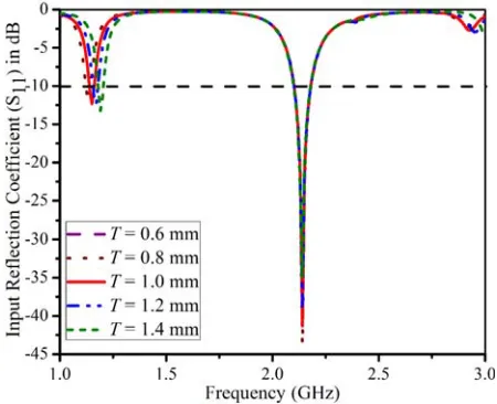
Figure 2. Simulated input reflection coefficients of the proposed antenna with varying CSRR thickness (T) of the proposed antenna.
Figure 3. Simulated input reflection coefficients of the proposed antenna with varying interdigital capacitor finger length (L3) of the proposed antenna.
of the proposed MTM antenna are shown in Table 1.
The design is based on CRLH metamaterial transmission line structure. It is observed that both modes are found using two different types of structure. It is verified by the parametric analysis that
n= 0 mode is due to rectangular type CSRR as shown in Figure 2 althoughn= 1 mode is found by the coupling between interdigital capacitor and rectangular type CSRR as shown in Figure 2(b). Figure 3 shows that the first order resonant frequency can be controlled by varying the length of inter-digital capacitor (L3) while there is no shift in the ZOR frequency. This is because the increase in length of the interdigital capacitor tends to increase series capacitance (left handed capacitance) which decreases the resonant frequency. In Figure 3, it is observed that frequencies are not shifted in large variations because right-handed inductance (LR) decreases at the same time tending to increase the frequency
slightly. Similarly, CSRR thickness (T) is used to drive the ZOR frequency as it decreases the shunt capacitance (CR) and increases shunt inductance (LL) simultaneously, by increasing CSRR thickness,
and thereby ZOR frequency is slightly increased, as shown in Figure 2. In addition, coupling capacitance between patch and ground plays a significant role in driving the ZOR frequency.
3. ANTENNA THEORY
Equivalent circuit model of the proposed antenna is shown in Figure 4. Interdigital capacitor can be modelled by the series capacitance (CL) whileLR shows the inductance associated with the interdigital capacitor (parasitic inductances) and feed line, thus forms the series LC circuit. Another subpart of the proposed antenna is CSRR which forms the parallel LC tank circuit. CC represents the coupling
capacitance induced by the current flow between patch and ground plane. It is observed that these parameters play significant roles in tuning the resonant frequency and hence electrical size of the antenna. Those lumped parameters are extracted by electromagnetic simulation. For the given dimensions, extracted values of the lumped elements are as shown in Table 2. It is realized that ZOR frequency can be controlled byCC,LLandCRwhile first-order resonant frequency can be tuned by series parameters,
e.g., LR andCL and slightly depending onCC.
The dispersion relation can be obtained by applying periodic boundary conditions related to the Bloch-Floquet theorem [9, 17]:
βd= cos−1
1 + zy 2
LR (nH) LL (nH) CL (pF) CR (pF) CC (pF)
9.44 2.654 0.614 7.056 0.17
z=
jωLR− j ωCL (2) Y = jωCc
jωCR− j ωLL
(3)
wheredis the physical length of the unit cell andβ the propagation constant. The CRLH unit cell can be used as a resonator under following condition:
βn= nπ
d (n= 0,±1,±2, . . . ,±(N −1)) (4)
where nand N are the resonant mode number and number of unit cells, respectively. For the zeroth-order mode these equations can be simplified by:
1 + CC
CR −
ωsh ωz 2 1− ωse ωz 2
= 0 (5)
where, ωsh = 1/√LLCR,ωse= 1/√LRCL, and ωz is the ZOR frequency. It is evident by Eq. (5) that for open circuit boundary conditions ZOR frequency can be given by:
ωZ =ωsh 1
1 +CC
CR
(6)
According to Eq. (6), the calculated ZOR frequency is 1.15 GHz, which is also confirmed by the simulation results. It is also evident that ZOR frequency can be further reduced by tuning Cc. For
Cc =CR, ZOR frequency is 0.707 times of the shunt resonant frequency.
Figure 5 shows a dispersion diagram of the proposed MTM antenna based on equivalent circuit parameters of the unit cell. The dispersion diagram can be categorized corresponding to RH region (β > 0) and LH region (β <0). These two curves are bounded by a bandgap which is determined by the series and shunt resonant frequencies. It is observed that RH modes may be found after 2.09 GHz while LH modes may be obtained below 1.15 GHz.
Figure 4. Equivalent Circuit model of the proposed antenna.
4. EXPERIMENTAL RESULTS
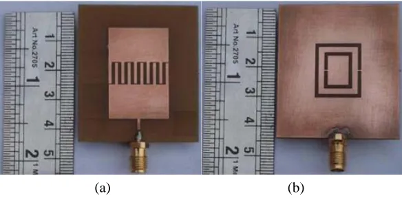
Figure 6 presents the prototype of the proposed antenna, which is fabricated on an FR4 glass epoxy substrate with thickness 1.6 mm. The measured and simulated input reflection coefficients of the proposed antenna are as shown in Figure 7. Corresponding measured fractional bandwidth of 5.3% (at the centre frequency 2.26 GHz) is found with an extension from 2.2 GHz to 2.32 GHz. Figure 8 shows the E-field distribution of the proposed antenna at 2.26 GHz and 1.15 GHz. It is clearly revealed that first order resonating frequency is due to coupling between interdigital capacitor and ground plane. It is also observed that ZOR frequency is due to the rectangular type CSRR.
Figure 6 shows the simulated and measured co- and cross-polarized radiation patterns inxz- and yz-planes at 2.26 GHz. It is observed that the antenna exhibits a monopole radiation pattern inyz-plane while dipolar-type pattern inxz- with shift in nulls of 90◦. The proposed antenna offers cross-polarization
(a) (b)
Figure 6. Photographs of the proposed antenna prototype, (a) top view, (b) bottom view.
Figure 7. Simulated and measured input reflection coefficient of the proposed antenna.
Table 3. Comparison with earlier published work.
Design & Feeding technique
Frequency (GHz)
Electrical Size of the whole antenna
Feeding Technique
This work 2.14 0.321λ0×0.285λ0×0.011λ0 Microstrip [9] 3.82 0.505λ0×0.442λ0×0.02λ0 Microstrip
with respect to the antenna reported earlier. In Table 3, the overall electrical size of the antenna is calculated rather than size of the patch.
(a)
(b)
Figure 8. E-field distribution of the proposed antenna, (a) at 2.26 GHz, (b) at 1.15 GHz.
(a) (b)
5. CONCLUSION
A compact planar metamaterial antenna using rectangular type CSRR and interdigital capacitor is proposed. In order to design a CRLH transmission line, interdigital capacitor and rectangular CSRR are integrated into the structure. It is observed that the dimensions of the antenna can be effectively miniaturized by varying the length of interdigital capacitor. An equivalent circuit model for the proposed antenna is presented and validated through parameter extraction method. It is seen that operating frequency can be tuned by varying the CSRR thickness, and thickness of the substrate as Cc is also
responsible for ZOR frequency. Dispersion relations are calculated by extracting the equivalent antenna design parameters. The overall electrical size of the antenna is 0.321λ0×0.285λ0×0.011λ0. By providing a rectangular type CSRR, ZOR mode is found. Good impedance matching of −45 dB is achieved with measured fractional bandwidth of 5.3% (at center frequency of 2.26 GHz). The proposed antenna has measured antenna gain of 2.6 dB with 70% simulated antenna efficiency.
ACKNOWLEDGMENT
The authors would like to thank Dr. K. V. Srivastava, Department of Electrical Engineering, IIT Kanpur, India, for providing the facility to measure the antenna prototype. Authors also thank to Dr. Mrinal Sen, ISM Dhanbad, India for providing assistance in fabricating the antenna prototype.
REFERENCES
1. Shelby, R. A., D. R. Smith, and S. Schultz, “Experimental verification of a negative index of refraction,” Science, Vol. 292, No. 5514, 77–79, 2001.
2. Caloz, C. and T. Itoh, “Novel microwave devices and structures based on the transmission line approach of metamaterials,” IEEE-MTT Int. Symp., Vol. 1, 195–198, Philadelphia, PA, USA, Jun. 2003.
3. Sanada, A., C. Caloz, and T. Itoh, “Novel zeroth order resonance in composite right/left-handed transmission line resonators,” Asia-Pacific Microwave Conference, Seoul, Korea, Nov. 2003. 4. Niu, B. J. and Q. Fang, “Bandwidth enhancement of CPW-fed antenna based on epsilon negative
zeroth and first-order resonators,”IEEE Antennas and Wireless Propagation Letters, Vol. 12, 1125– 1128, 2013.
5. Kim, T. G. and B. Lee, “Metamaterial based compact zeroth order resonant antenna,” Electronics Letters, Vol. 45, No. 1, 12–13, 2009.
6. Dong, Y. and T. Itoh, “Miniaturized substrate integrated waveguide slot antennas based on negative zeroth order resonance,”IEEE Transactions on Antennas and Propagation, Vol. 58, No. 12, 3856– 3864, 2010.
7. Antoniades, M. A. and G. V. Eleftheriades, “A folded-monopole model for electrically small NRI-TL metamaterial antennas,” IEEE Antennas and Wireless Propagation Letters, Vol. 7, 425–428, 2008.
8. Schubler, M., J. Freese, and R. Jakoby, “Design of compact planar antennas using LH-transmission lines,”IEEE MTT-S Int. Microw. Symp. Dig., 209–212, Fort Worth, TX, Jun. 2004.
9. Ha, J., K. Kwon, Y. Lee, and J. Choi, “Hybrid mode wideband patch antenna loaded with a planar metamaterial unit cell,” IEEE Transactions on Antennas and Propagation, Vol. 60, No. 2, 1143–1147, 2012.
10. Jang, T., J. Choi, and S. Lim, “Compact coplanar waveguide (CPW)-fed zeroth-order resonant antennas with extended bandwidth and high efficiency on a vialess single layer,”IEEE Transactions on Antennas and Propagation, Vol. 59, No. 2, 363–372, 2011.
13. Mart´ınez, F. J. H., G. Zamora, F. Paredes, F. Mart´ın, and J. Bonache, “Multiband printed monopole antennas loaded with OCSRRs for PANs and WLANs,” IEEE Antennas and Wireless Propagation Letters, Vol. 10, 1528–1531, 2011.
14. Sharma, S. K., A. Gupta, and R. K. Chaudhary, “Compact CPW-fed CHSSR antenna for WLAN,” IEEE International Microwave and RF Conference (IMaRC), 115–117, Bangalore, 2014.
15. Baena, J. D., J. Bonache, J. F. Martin, et al., “Equivalent-circuit models for split-ring resonators and complementary split-ring resonators coupled to planar transmission lines,”IEEE Transactions on Microwave Theory and Techniques, Vol. 53, No. 4, 1451–1461, 2005.
16. Si, L.-M. and X. Lv, “CPW-fed multi-band omni-directional planar microstrip antenna using composite metamaterial resonators for wireless communications,” Progress In Electromagnetics Research, Vol. 83, 133–146, 2008.
17. Lai, A., K. M. K. H. Leong, and T. Itoh, “Infinite wavelength resonant antennas with monopolar radiation pattern based on periodic structures,”IEEE Transactions on Antennas and Propagation, Vol. 55, No. 3, 868–876, 2007.