A Case Study on Control Application of PV-STATCOM for Reactive Power
Compensation during Day and Night in a Transmission Network
Hariom Narware
1, Mr.Durgesh Vishwakarma
21
M.Tech Scholar, EEE department, Radharaman Engineering College, Bhopal
2
A EEE department, Radharaman Engineering College, Bhopal
Abstract:
Solar Farms are absolutely idle in the night and even during daytime operate below capacity in early mornings and late afternoons. Thus, the entire expensive asset of solar farms remains highly unutilized. This paper presents novel technologies for utilization of PV solar farm inverter in nighttime for providing multiple benefits to power systems, as well as accomplishing the same objectives during the daytime from the inverter capacity left after production of real power. The new technology transforms a solar farm inverter functionally into a dynamic reactive power compensator known as STATCOM, and termed PVSTATCOM. Novel PVSTATCOM control is employed to significantly enhance the power transfer limit of a long transmission line both in the nighttime and also during daytime even when the solar farm is producing a large amount of real power. This technology can open up new avenues for solar farms to earn revenues apart from the sale of real power.
Keywords
Photovoltaic (PV) Solar Farms, Inverter Modeling, STATCOM, PV-STATCOM, Reactive Power Compensation, Voltage Control, Damping Control, Power factor correction.
1.
Introduction
This chapter presents a new application of a grid connected PV solar farm inverter as a PV-STATCOM, during both night and day for increasing transient stability and consequently, the power transmission limit of long transmission line. It utilizes the entire solar farm inverter capacity during the night and the remainder inverter capacity after real power generation during the day; both of which remain unused in conventional solar farm operation. Similar STATCOM control functionality can also be implemented in inverter based wind turbine generators during no-wind or partial wind scenarios
for improving the transient stability of the system. Studies are performed for two variants of a Single Machine Infinite Bus (SMIB) system. One SMIB system uses only a single PV solar farm as PV-STATCOM connected at the midpoint; whereas, the second system uses a combination of a PV-STATCOM and another PV-PV-STATCOM or an inverter based wind Distributed Generator (DG) with similar STATCOM functionality. Three-phase fault studies are conducted using the MATLAB/SIMULINK software, and the improvement in stable power transmission limit is investigated for different combinations of STATCOM controllers on the solar and wind farm inverters, during both night and day.
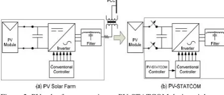
A conventional grid connected Photovoltaic PV solar farm utilizes an inverter for converting the DC power output from PV arrays into AC power to be supplied to the grid. The STATCOM (a FACTS device) is also based on a voltage sourced converter which functions both as an inverter and rectifier. A novel control technology was proposed by which a PV solar farm can be operated as a STATCOM in the night time as well as during day. During the night time the entire inverter capacity of the PV solar farm is utilized as STATCOM, whereas during the day, the inverter capacity remaining after real power generation is utilized for STATCOM operation. Since this STATCOM is based on a PV solar system, it has been given the name PV-STATCOM. This technology can open up new avenues for solar farms to earn revenues apart from the sale of real power. This will require appropriate agreements between the regulators, network utilities, solar farm developers and inverter manufacturers.
2.
Literature Survey
Many investigations have been carried out on the performance of PV-STATCOM and voltage source inverters. A brief review of literature in this regard is presented in this session. Paper [1] proposes a novel voltage control together with auxiliary damping control for a grid connected PV solar farm inverter to act as a STATCOM both during night and day for increasing transient stability and consequently the power transmission limit. It utilizes the entire solar farm inverter capacity in the night and the remainder inverter capacity after real power generation during the day, both of which remain unused in conventional solar farm operation. Similar STATCOM control functionality can also be implemented for wind. Three-phase fault studies are conducted using the electromagnetic transient software EMTDC/PSCAD, and the improvement in stable power transmission limit is investigated for different combinations of STATCOM controllers on the solar farm inverters, both during night and day.
Paper [2] presents the real-time digital simulation of a novel control of PV inverter as STATCOM for power factor correction and voltage regulation on a Real-Time Digital Simulator (RTDS). The controller design for the PVSTATCOM is based on controller esigns already presented. In addition, a description of the unique research lab facility created at London Hydro is also provided. This Lab will be utilized for testing the PV-STATCOM, in addition to conducting other Distributed Generator Controls research. The PV-STATCOM technology is expected to be showcased on the local distribution company London Hydro‘s distribution feeder for the first time in Canada, in late 2012.
Paper [3] describes modeling and optimization of STATCOM on AC bus of Micro grid. The paper begins with explaining STATCOM as a potential solution to voltage fluctuations and reactive power demand on the AC bus and extends to dealing with the control strategies required for the operation of STATCOM.
Paper [4] presents a utilization of the PV solar farm inverter as a STATCOM—a FACTS device for voltage control and power correction, both during for voltage control and power factor correction has been developed which provides voltage regulation and load compensation in the nights utilizing the entire capacity of the existing solar systems inverter. During daytime also, the solar system is made to operate as a STATCOM using its remaining inverter capacity (left after what is needed for real power generation).
Paper [5] contains Particle Swarm Optimization (PSO) is an evolutionary technique that is used to solve multi objective optimization problem. In this
paper PSO technique is used to estimate the feasible optimal setting for the TCSC device to enhance the power transfer capability of the system to an appreciable limit.
This paper proposes novel voltage control, together with auxiliary damping control, for a grid-connected PV solar farm inverter to act as a STATCOM both during night and day for increasing transient stability and consequently the powertransmission limit. This technology of utilizing a PV solar farm as a STATCOM is called ―PV-STATCOM.‖ It utilizes the entire solar farm inverter capacity in the night and the remainder inverter capacity after real power generation during the day, both of which remain unused in conventional solar farm operation.
3.
Methodology
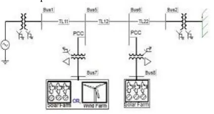
The single-line diagrams of two study systems: Study System 1 and Study System 2 are depicted in Fig. 1(a) and (b), respectively. Both systems are single-machine infinite bus (SMIB) systems where a large equivalent synchronous generator (1110 MVA) supplies power to the infinite bus over a 200-km, 400-kV transmission line. This line length is typical of a long line carrying bulk power in Ontario.
Fig 1: Single-line diagram of (a) study system I with a single solar farm (DG)
Fig. : 1 Single-line diagram of (b) study system II with a solar farm (DG) and a solar/wind farm (DG).
SMIB system in which a large equivalent synchronous generator (1110 MVA) operating at 22kV system supplies power to the infinite bus over a 200 km, 400 kV transmission line. An 1110 MVA, 22/400kV transformer having leakage reactance of 8.66% is coupled with the generator. This line length is typical of a long line carrying bulk power in Ontario. In Study System 1, a 100 MW PV solar farm (DG) as a STATCOM (PV-STATCOM) is connected at the midpoint of the transmission line.
Author names and affiliations are to be centered beneath the title and printed in Times 12-point, non-boldface type. Multiple authors may be shown in a two- or three-column format, with their affiliations below their respective names. Affiliations are centered below each author name, italicized, not bold. Include e-mail addresses if possible. Follow the author information by two blank lines before main text.
Figure 2: PV solar farm operation as PV-STATCOM during night and day
In Study System 2, two 100-MVA inverter based distributed generators (DGs) are connected at 1/3 (bus 5) and 2/3 (bus 6) of the line length from the synchronous generator.
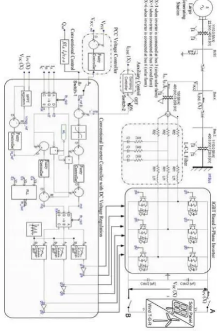
This paper describes a new control method to maintain the STATCOM DC link voltage to a minimum value in their paper. The additional PV cell acts as a backup to the STATCOM DC link voltage source. It serves as a source to the STATCOM DC link capacitor when the capacitor voltage is below a particular limit. This control method along with STATCOM improves the output waveform quality and improves the reliability of the system. In this case, the wind farm employs permanent-magnet synchronous generator (PMSG)-based wind turbine generators with a full ac-dc-ac converter. It is understood that the solar DG and wind DG employ several inverters. However, for this analysis, each DG is considered to have a single equivalent inverter with the rating equal to the total rating of solar DG or wind DG, respectively. Fig. 2 presents the block diagrams of various subsystems of two equivalent DGs.
A .System Model
The synchronous generator is represented by a detailed sixth order model and a DC1A-type exciter. The transmission-line segments TL1, TL2, TL11, TL12, and TL22, shown in Fig. 1, are represented by lumped pi-circuits. The PV solar DG, as shown in Fig. 2, is modeled as an equivalent voltage-source inverter along with a controlled current source as the dc source which follows the - characteristics of PV panels. The wind DG is likewise modeled as an equivalent voltage-source inverter. In the solar DG, dc power is provided by the solar panels, whereas in the full-converter-based wind DG, dc power comes out of a controlled ac–dc rectifier connected to the PMSG wind turbines, depicted as “wind Turbine-Generator-Rectifier (T-GR).” The dc power produced by each DG is fed into the dc bus of the corresponding inverter.
To avoid this resonance from contaminating the system, several damping techniques have been proposed. One way is to incorporate a physical passive element, such as, a resistor in series with the filter capacitor. LCL filter is usually placed between the inverter and the grid to attenuate the switching frequency harmonics produced by the grid-connected inverter. Compared with L filter, LCL filter has better attenuation capacity of high-order harmonics and better dynamic characteristics. LCL filter has good current ripple attenuation even with small inductance values. However it can bring also resonances and unstable states into the system. Therefore the filter must be designed precisely according to the parameters of the specific converter. The MPPT algorithm [12] is used to operate the solar DGs at its maximum power point all of the time and is integrated with the inverter controller. The wind DG is also assumed to operate at its maximum power point, since this proposed control utilizes only the inverter capacity left after the maximum power point operation of the solar DG and wind DG. For PV-STATCOM operation during nighttime, the solar panels are disconnected from the inverter and a small amount of real power is drawn from the grid to charge the dc capacitor. Each phase has a pair of IGBT devices which converts the dc voltage into a series of variable-width pulsating voltages, using the sinusoidal pulse width modulation (SPWM) technique. An L-C-L filter is also connected at the inverter ac side.
B. Control System
1) Conventional Reactive Power Control:
through two current control loops in coordinate system. The inverter operates in a conventional controller mode only provided that “Switch-2” is in the “OFF” position.
2) PCC Voltage Control:
In the PCC voltage control mode of operation, the PCC voltage is controlled through reactive power exchange between the DG inverter and the grid. The conventional control channel is replaced by the PCC voltage controller in Fig.3. It depends upon the set point voltage at the PCC the amount of reactive power flow from the inverter to the grid. To achieve the fastest step response, least settling time, the parameters of the PCC voltage controller is tuned by a systematic trial-and-error method and a maximum overshoot of 10%–15%.
3) Damping Control:
A novel auxiliary damping controller is added to the PV control system and shown in Fig.3. This controller utilizes line current magnitude as the control signal. The output of this controller is added with the signal.
The transfer function of this damping controller is expressed as in
(1)
The transfer function is comprised of a gain, a washout stage, and a first-order lead-lag compensator block. This controller is utilized to damp the rotor-mode oscillations of the synchronous generator and thereby improve system transient stability. The damping controller is activated by toggling “Switch-2” to the “ON” position.
This damping controller can operate in conjunction with either the conventional reactive power control mode or with the PCC voltage-control mode by toggling “Switch-1” to position “B” or “A”.
4.
Case Studies
Transient stability studies are carried out using simulation, for both the study systems during night and day, by applying a three-line-to-ground (3LG) fault at bus 1 for five cycles. The damping ratio is used to express the rate of decay of the amplitude of oscillation [20]. For an oscillatory mode, the damping ratio is defined as
(2)
Where, is the time constant.
Therefore, for a 5% damping ratio of the rotor mode having an oscillation frequency of 0.95Hz. As considered in this study, the post fault clearance settling time of the oscillations to come within 5%.
A. Case Study 1: Power Transfer Limits in Study System 1
Conventional Reactive Power Control With Novel Damping Control: A new control study is proposed here.
In this study, the solar DG is assumed to operate with its conventional reactive power controller and the DG operates at near unity power factor. For the nighttime operation of solar DG, the dc sources (solar arrays) are disconnected, and the solar DG inverter is connected to the grid using appropriate controllers, as will be described. Power transmission limits are now determined for the following four cases.
Fig. 3. Complete DG (solar/wind) system model with a damping controller and PCC voltage-control system.
The stable power transmission limits obtained from transient stability studies and the corresponding load-flow results are presented in Table II where represents the inductive power drawn respectively. At first, the base-case generator operating power level is selected for performing the damping control design studies. This power level is considered equal to the transient stability limit of the system with the solar farm being disconnected at night.
STATCOM using these reasonably good controller parameters. In this controller, although the line current magnitude signal is used, other local or remote signals, which reflect the generator rotor mode oscillations, may also be utilized.
TABLE I
Power Flows And Voltages For Study System I For Solar Dg With Conventional Reactive Power Control And Proposed Damping Control Both During Nighttime And Daytime (1.05 P.U.)
Solar DG Operation during Night with
Conventional Reactive Power Controllers:
The maximum stable power output from the generator is 731 MW when the solar DG is simply sitting idle during night and is disconnected from the network. This power-flow level is chosen to be the base value against which the improvements in power flow with different proposed controllers are compared and illustrated later in Table III.
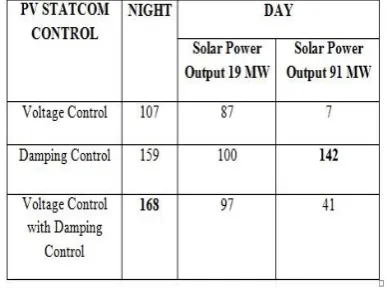
TABLE II
Increase In The Stable Power Transfer Limit (In Megawatts) For Study System I With Different Pv-Statcom Controls
Solar DG Operation During the Night With a Voltage Controller:
The increase in the power transfer limit depends upon the choice of reference values for PCC voltage . In the best scenario when is regulated to 1.01 p.u., the maximum power output from the generator increases to 833 MW, compared to 731 MW when the solar DG operates with conventional reactive power control.
TABLE III
Power Flows And Voltages For Study System I For Solar Dg With The Proposed Pcc Voltage Control And Damping Control During Nighttime And Daytime (1.05 P.U.)
TABLE IV
Power Flows And Voltages For Study System Ii For Both Solar Dg And Wind Dg With Conventional Reactive Power Control And
Proposed Damping Control Both During
TABLE V
Increase In Power Transfer Limits For Study System Ii With Different Dg Power Outputs
5. Implementation of PV-STATCOM on
Large-Scale Solar Systems
For the first time in a utility network of a 10-kW PV solar system the PV-STATCOM technology will be shown. The 10-kW solar system will be utilized for voltage regulation and power factor correction in addition to generating real power.
The PV-STATCOM will be allowed to connect to the wires of the utility. These include: 1) PV-STATCOM controller testing with Matlab simulation studies; 2) controller validation using real-time digital simulation (RTDS) [21]; and, finally, 3) a full-scale 10-kW lab-scale demonstration of the PVSTATCOM.
List and number all bibliographical references in 9- point Times, single-spaced, at the end of your paper. When referenced in the text, enclose the citation number in square brackets, for example [2-4], [2, 5], and [1].
6. CONCLUSION
Power system performance depends on the flow of real and reactive power and adequate control method is required to control the flow of real and reactive power in the system. In this paper a novel concept of utilizing a photovoltaic (PV) solar farm inverter as STATCOM, called PV-STATCOM using fuzzy controller is proposed. The PV-STATCOM operation opens up a new opportunity for PV solar DGs to earn revenues in the nighttime and daytime in addition to that from the sale of real power during the day. FACTS controllers are versatile in controlling either by impedance varying or by using switching power electronics method. Solar farms are idle during nights. This new control of PV solar system as STATCOM is called PV-STATCOM. The main function of the LCL filter is to reduce high-order harmonics on the output side; however poor design may cause a distortion increase. Three different types of STATCOM controls are proposed for the PV solar DG and inverter-based wind DG. These are pure voltage control, pure damping control, and a combination of voltage control and damping control. The proposed method is verified by using the simulation results.
7. REFERENCES
[1] R. M. Mathur and R. K. Varma, Thyristor-Based FACTS Controllers for Electrical Transmission Systems. Hoboken, NJ, USA: Wiley/IEEE, 2002. [2] S. A. Rahman, R. K. Varma, and W. Litzenberger, “Bibliography of FACTS applications for grid integration of wind and PV solar power systems: 1995–2010, IEEE working group report,” presented at the IEEE Power Energy Soc. Gen. Meeting, Detroit, MI, USA, Jul. 2011.
[3] Y. Xiao, Y. H. Song, C.-C. Liu, and Y. Z. Sun, “Available transfer capability enhancement using FACTS devices,” IEEE Trans. Power Syst., vol. 18, no. 1, pp. 305–312, Feb. 2003.
[5] R. K. Varma, V. Khadkikar, and R. Seethapathy, “Nighttime application of PV solar farm as STATCOM to regulate grid voltage,” IEEE Trans. Energy Convers., vol. 24, no. 4, pp. 983–985, Dec.2009.
[6] R. K. Varma and V. Khadkikar, “Utilization of solar farm inverter as STATCOM,” U.S. Provisional Patent, Sep. 15, 2009.
[7] R. K. Varma, S. A. Rahman, and R. Seethapathy, “Novel control of grid connected photovoltaic (PV) solar farm for improving transient stability and transmission limits both during night and day,” in Proc. World Energy Conf., Montreal, QC, Canada, 2010, pp. 1–6.
[8] R. A. Walling and K. Clark, “Grid support functions implemented in utility-scale PV systems,” in Proc. IEEE Power Energy Soc, Transm. Distrib. Conf. Expo., 2010, pp. 1–5.
s[9] F. L. Albuquerque, A. J. Moraes, G. C. Guimaraes, S. M. R. Sanhueza, and A. R. Vaz, “Photovoltaic solar system connected to the electric power grid operating as active power generator and reactive power compensator,” Solar Energy, vol. 84, no. 7, pp. 1310–1317, Jul. 2010.