© 2015, IRJET.NET- All Rights Reserved
Page 61
Optimized Design and Implementation of a 16-bit Iterative Logarithmic
Multiplier
Laxmi Kosta
1, Jaspreet Hora
2, Rupa Tomaskar
31
Lecturer, Department of Electronic & Telecommunication Engineering, RGCER, Nagpur,India,
2
Lecturer, Department of Electronic & Telecommunication Engineering, RGCER, Nagpur,India,
3
Lecturer, Department of Electronic & Telecommunication Engineering, WCEM, Nagpur,India,
---***---Abstract -
In many real-time DSP applications,performance is a prime target. However, achieving high performance may be done at the expense of area and power dissipation. Attempts have been made to use alternative number systems to optimize the realization of arithmetic blocks, so as to maintain high performance without increasing area and power. For this we used Logarithmic Number System in base two. By using this number system, we can achieve highly
optimized realizations of functions such as
multiplication, division and square root. Complex multiplication is one of the critical operations in various wireless and DSP applications. Complex
multiplication requires a large area for
implementation and consumes high power as the input width increases from 16 to 32 bits. Using the Logarithmic Number System can transform this operation into few additions and subtractions. The corresponding savings can even compensate for the additional costs of number system conversions at the input and output. In this paper we have design an optimized logarithmic multiplier based on Mitchell’s Algorithm [1]. The design uses an iterative method to implement the logarithmic multiplier so as to increase the speed of multiplication, and reduce the number of logic blocks used to design it. For the design entry, we used the Xilinx ISE 13.2 - Web-PACK and designed with Verilog HDL. The design was synthesized with the Xilinx XST Release 13.2 for Windows. When using Xilinx xc3s1500-5fg676 device, the pipelined implementation of the basic block uses 4.63% fewer number of slices and 6.93% fewer number of 4 input LUTs than the reference design [8]. The total power consumed by the pipelined basic block is 2.92% less than the reference design [8].
Key Words:
Verilog HDL, Logarithmic Number
System, Xilinx, LUT
1.INTRODUCTION
Multiplication is a fundamental operation in most signal processing algorithms. As multipliers have large area, long latency and consume considerable power, therefore high speed multiplier design has been an important part in VLSI system design. There has been extensive work on high speed multipliers at technology, physical, circuit and logic levels. As of systems performance is generally determined by the performance of the multiplier because the multiplier is generally the slowest element in the system. Also multiplier is the most area consuming element. Therefore while designing the important issue is to optimize the speed and area of the multiplier.
1.1
Logarithmic Multiplication Methods
In logarithmic multiplication, the input operands are first converted into equivalent logarithms, and then the logarithms of the two operands are added together and finally the antilogarithm of the resultant sum is taken to get the final result. The advantage is that multiplication is replaced by addition. LNS multipliers can be generally divided into two categories, first is based on lookup tables method and interpolations, and the second one is based on Mitchell’s algorithm (MA) [1].
A binary number, N in the interval where
& can be represented
as:
(1)
or (2) where
© 2015, IRJET.NET- All Rights Reserved
Page 62
(4) where k is referredto the characteristic of the number and m represents the binary fraction or the mantissa.
Mitchell’s Algorithm:
One of the most significant multiplication methods in LNS is Mitchell’s algorithm. It is essential to approximate the values of logarithm and the antilogarithm which can be derived from a binary representation of the numbers.The logarithm of the product is
(5) The expression is approximated with and the logarithm of the two number’s product is expressed as the sum of their characteristic numbers and mantissas:
(6)
The characteristic numbers and represent the places of the most significant operands’ bits with the value of ‘1’. For 16-bit numbers, the range for characteristic numbers is from 0 to 15. The fractions and are in range [0, 1). The final MA approximation for the multiplication where depends on the carry bit from the sum of the mantissas and is given by:
(7)
The final approximation for the product (7) requires the comparison of the sum of the mantissas with ‘1’.The sum of the characteristic numbers determines the most significant bit of the product. After that the sum of the mantissas is then scaled (shifted left) by or
by , depending on the .
If , the sum of mantissas is added to the most significant bit of product to complete the final result. Otherwise, we approximate the product only with the scaled sum of mantissas.
Algorithm 1:
1. : n-bits binary multiplicands, = 0:2 n-bits approximate product
2. Calculate : leading one position of 3. Calculate : leading one position of
4. Calculate : shift to the left by bits 5. Calculate : shift to the left by bits 6. Calculate
7. Calculate 8. IF
(a) Calculate
(b) Decode and insert in that position of ELSE:
(a) Decode and insert ‘1’ in that position of (b) Append immediately after this one in 9. Approximate
The MA produces a significant error percentage. The relative error increases with the number of bits with the value of ‘1’ in the mantissas. The maximum possible relative error for MA multiplication is around 11%, and the average error is around 3.8% .The error in MA is always positive so it can be reduced by successive multiplications.
Mitchell analyzed this error and proposed the following analytical expression for the error correction:
(8)
where and are the
correction terms proposed by Mitchell.
To calculate the correction terms we have to:
1. Calculate or depending on
in the same way as described in (7), 2. Scale the correction term by the factor , 3. Add the correction term to the product .
1.2
An Iterative Algorithm Based Logarithmic
Multiplier:
A binary number can be written as:
(9)
where k is referred to the characteristic of the number and m represents the binary fraction or the mantissa.
We can derive a correct expression for the multiplication:
(10)
To avoid the approximation error, we have to take into account the next relation derived from (9):
(11)
The combination of (10) and (11) gives:
(12)
Let
(13) be the first approximation of the product.
© 2015, IRJET.NET- All Rights Reserved
Page 63
(14)Instead approximating the product as proposed in (12), we can calculate the product in the same way as and repeat the procedure until exact result is obtained.
Algorithm 2:
1. , : n-bits binary multiplicands, 0: 2n-bits
first approximation, 0: 2n-bits correction terms, = 0: 2n-bits product
2. Calculate : leading one position of 3. Calculate : leading one position of
4. Calculate : shift to the left by bits
5. Calculate : shift to the left by bits
6. Calculate
7. Calculate : decode
8. Calculate : add , and
9. Repeat -times or until. , or :
(a) Set: , (b) Calculate :
leading one position of
(c) Calculate : leading one position of
(d) Calculate : shift to the left by bits\
(e) Calculate : shift to the left by bits
(f) Calculate
(g) Calculate : decode
(h) Calculate : add , and
10.
One of the advantages of the proposed solution is the possibility to achieve an arbitrary accuracy by selecting the number of iterations, i.e., the number of additional correction circuits, but more important is that the calculation of the correction terms can start immediately after removing the leading ones from the original operands.
2.
Hardware Implementation
:
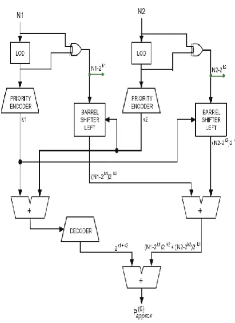
A basic block (BB) is a simple multiplier with no correction terms. The main function of the basic block is to calculate one approximate product according to (12). The 16-bit basic block is presented in Figure1. This basic block consists of two leading-one detectors (LODs), two 32-bit barrel shifters, a decoder unit and one 4-bit, two encoders and two 32-bit adders.
In the basic block, inputs operands are applied to the LOD units. The LOD units are used to remove the leading one from the operands. The input operands and the output of the LOD are then XORed, to get rid of the leading one of the input operands. The output of the LOD is then applied to the priority encoder to encode the value of the leading one in the input operands. The output from the XOR gate is then shifted with the help of barrel shifter according to the encoded value from the priority encoder. The encoded values from the priority encoders are then added together and decoded, similarly the output from the barrel shifters are added together. The decoded value of the adder and the sum of barrel shifters output, are then again added to form the output of the basic block.
Fig 1: Block Diagram of Basic Block
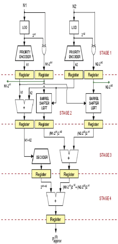
2.1 Pipelined implementation of the basic block:
To decrease the maximum combinational delay in the basic block, we used pipelining to implement the basic block from Figure 1. The pipelined implementation of the basic block is shown in Figure 2and has four stages. The stage 1 calculates the two characteristicnumbers , and the two
© 2015, IRJET.NET- All Rights Reserved
Page 64
and . The stage 4
calculates the approximation of the product .
Fig 2: A pipelined basic block
2.2
Constraints of the implemented design:
Following are the constraints of the implemented design proposed in this thesis work:
1) The presented implementation of the logarithmic multiplier is for unsigned numbers i.e. the input to
this module must only be unsigned numbers. For signed input operand the output will not be correct.
2) The presented design will work for all unsigned numbers except zero input operand. According to the design, the output will be unknown for zero input operand.
3.
Simulation Results:
The simulation waveform of the pipelined implementation of the basic block is shown in the figure 3.Here when the reset pin is high, the output is zero. The output is unknown for the zero input operands. On applying the input operands, the output appears after the fourth clock cycle.
Fig 3: Simulation waveform of pipelined basic block
4.
Discussions
Here we compare our design for the number of slices, number of 4-input LUTs used to implement the design on the target chip also the power consumption at 25 MHz clock frequency. The data for comparison are taken from the reference paper [8].
© 2015, IRJET.NET- All Rights Reserved
Page 65
Table -1: Comparison of the implemented design of the module with reference design [8]
Module Referenc
For non-pipelined implementation of basic block the design uses 31.16% fewer number of slices and 30.21% 4.86% fewer number of 4-input LUTs. The pipelined basic block with two error correction unit uses 2.52% fewer number of slices and 3.36% fewer number of 4-input LUTs.
The comparison of total power consumed by the implemented design with the reference design [8] is shown in table 2.For the pipelined implementation of basic block, there is a reduction of 2.92% of total power consumed. The pipelined basic block with one error correction unit uses 1.70% less total power. The pipelined
basic block with two error correction unit uses 3.42% less total power.
Table -2:Comparison of total power consumed by the implemented design with the reference design [8]
Module Total using binary logarithms, IRE Transactions on Electronic Computers EC-11 (1962) 512–517.
[2] K.H. Abed, R.E. Sifred, CMOS VLSI implementation of a low-power logarithmic converter, IEEE Transactions on Computers 52 (11) (2003) 1421–1433.
[3] K.H. Abed, R.E. Sifred, VLSI implementation of a low-power leading one detector, IEEE Transactions on Computers (2003)
[4] S Ramaswamy, R. Siferd, “CMOS VLSI implementation of a digital logarithmic multiplier”. Proceedings of the IEEE Notional Aerospace and Electronics Conference, vol 1, pp 291-294. May1996
[5] K.H. Abed, R.E. Sifred, VLSI implementation of a low-power antilogarithmic converter, IEEE Transactions on Computers 52 (9) (2003) 1221–1228.
[6] D.J. Mclaren, Improved Mitchell-based logarithmic multiplier for low-power DSP applications, in: Proceedings of IEEE International SOC Conference 2003,17–20 September 2003, pp. 53–56.
© 2015, IRJET.NET- All Rights Reserved
Page 66
decomposition, IEEE Transactions on Computers55 (2)(2006) 1523–1535.
[8] Z. Babic, A. Avramovic, P. Bulic,”An iterative logarithmic multiplier”, 2010 IEEE Transactions on Computer Design(ICCD), pp.235-240.
[9] Samir Palnitkar, Verilog HDL: A Guide to Digital Design and Synthesis
[10]J. Bhasker, Verilog HDL Synthesis, A Practical Primer [11] Michael D. Ciletti, Advanced Digital Design with the Verilog HDL
[12] Stephen Brown &ZvonkoVranesic, Fundamentals of Digital Logic with Verilog Design
[13] M.Morris Mano, Computer System Architecture [14] Xilinx ISE WebPACK Design Software, 2010 <http://www.xilinx.com/tools/ webpack.htm>.
[15] Xilinx Inc. Spartan-3 FPGA Data Sheets, 2009 <http://www.xilinx.com/
support/documentation/spartan-3_data_sheets.htm>.
BIOGRAPHIES
Mrs. Laxmi Kosta is currently working as Lecturer in RGCER, Nagpur in ETC Department. Completed M.Tech (Embedded System &VLSI Design) from GGITS, Jabalpur (MP) and B.E.(Electronics & Communication Engineering) from Jabalpur Engineering College, Jabalpur (MP)
Ms. Jaspreet Hora is currently working as Lecturer in RGCER, Nagpur in ETC Department. Completed M.Tech (VLSI) from GHRAET, Nagpur and B.E.(Electronics) from RTMNU, Nagpur
![Table -1: Comparison of the implemented design of the module with reference design [8]](https://thumb-us.123doks.com/thumbv2/123dok_us/976841.1120217/5.595.302.553.163.451/table-comparison-implemented-design-module-reference-design.webp)
