ISSN: 1992-8645 www.jatit.org E-ISSN: 1817-3195
DYNAMIC PARTIAL PATH-LOSS COMPENSATION-BASED
POWER CONTROL TECHNIQUE IN LTE-A FEMTOCELL
NETWORKS
Sawsan Ali Saad,Mahamod Ismail, Rosdiadee Nordin
Department of Electrical, Electronic and Systems Engineering, National University of Malaysia
E-mail: {Sawsan_3,mahamod,adee}@eng.ukm.my
ABSTRACT
With the femtocells being overlaid onto the macrocell in two-tier architecture, that comprises a mixture of both planned and arbitrary deployed nodes. This increases the data rate for indoor environment and fulfils the dream of high speed wireless and mobile broadband services. However, this potential for significant data rate growth could severely be diminished by cross and co-tier interference problem especially in a dense femtocell deployment scenario. In this paper, a dynamic power control scheme is proposed to mitigate the downlink interference in order to reduce the outage probability of macro user equipment (MUE), while maintaining good QoS for the home user equipment (HUE). The femtocell adjusts the transmit power, which subject to HUE measurements. The minimum level of transmit power is constrained to the target Signal to Interference and Noise Ratio (SINR) of the HUE that satisfy the required Quality of Service (QoS) of the HUE. The system level simulations confirm that, the proposed power control scheme reduces the outage probability of the nearby MUEs up to 23%, compared to fixed power setting, while maintaining the spectral efficiency of the HUEs. Furthermore, the transmit power can be reduced by 50%, which leads to effective power solution for the interference scenario.
Keywords: Co/Cross-Tier Interference, Femtocells, Macrocells, Power Control, Heterogeneous Network.
1. INTRODUCTION
The dramatic increase of indoor voice and data usage creates a real challenge for wireless communication operators, as the majority of indoor users suffer from poor service quality [1]. That limits the users to enjoy the high data speed and the enhanced capacity of the LTE-A from the mobile operators. Recently the concept of femtocell has attracted much attention in the wireless communication industry, to complement the conventional outdoor macro base stations [2]. Femtocell which is also known as Home enhanced NodeB (HeNB) in the 3rd Generation Partnership Project (3GPP) Long Term Evolution-Advanced (LTE-A) standard is a small size, low power (<=20 dBm) base station with short service range (<30 m) and can support less than ten users simultaneously [3]. HeNB is considered as a plug-and-play consumer device, which is easily installed by the consumers. Femtocell utilizes the existing broadband internet access, e.g. Digital Subscriber Line (DSL), cable modem or optical fiber connection as a backhaul to communicate with the mobile operator’s core network [4]. Femtocells
have many attractive features, such as low deployment cost and offload traffic from the macrocell [5]. Femtocells are expected to remarkably reduce the capital expenditure (CAPEXs) and operational expenditure (OPEXs), obviating the need to deploy costly infrastructure by reusing existing broadband connections; while providing enhanced indoor coverage and high data rates. [6].
ISSN: 1992-8645 www.jatit.org E-ISSN: 1817-3195 performance of authorized users in a particular
femtocell [8].
The transmit power level of a femtocell base station affects its coverage range and the amount of interference it generates in the network [9]. Although high femtocell transmit power provides wider coverage and better signal quality, at the same time it causes tremendous interference to other surrounding users of the adjacent macrocell networks [10]. Proper tuning of the femtocell transmit power varies the interference scenarios [11]. Femtocell has extensive self-organization capabilities to enable simple plug-and-play deployment. It is also designed to integrate automatically into an existing macrocell network. These self-capabilities are implemented using several algorithms that automatically change certain network configuration parameters (radiated power, channels, neighbor list, and handover parameters) in response to any change in the environment it is operating in [12]. For successful deployment of self-organization, there are three main functions need to be performed: (i) Self-configuration in pre-operational state, (ii) Self-optimization in an operational state, and (iii) Self-healing in case of failure of a network element.
One example of self-organizing capabilities in femtocell deployments is power optimization. Self-configuration function can transmit power based on the measurement of interference from neighbouring base stations in a manner that achieves roughly constant cell coverage. The HeNB then performs a self-optimization function that continually adjusts the transmit power, so that the femtocell coverage does not leak to the outdoor area, while guaranteeing quality indoor coverage for the femtocell users [13]. Although femtocells are low power base stations, the massive deployment of them will result in increasing the total power consumption of the LTE-A network [14]. Therefore, efficient methods, such as sleep mode and power control are used to reduce the power consumption, while maintaining the performance of femtocells [15]. Power control techniques can be classified into centralized and distributed techniques. The centralized power control technique needs a central controller and global information of all the link gains. It requires extensive control signalling in the network and it is subject to delays and congestion of wireline internet access. On the contrary, distributed technique only uses local information to control the transmit power. It is easier to implement considering the
decentralized nature of the femtocells and the uncertainty about the number and location of the nearby femto base stations [16].
In this paper, a dynamic fractional pathloss compensation based power control scheme for interference mitigation in LTE-Advanced macro/femto networks is proposed; to reduce the outage of the MUEs, while maintaining the performance of the HUEs. The scheme allows the implementation of the concept, whereby the coverage follows HUE, without requiring HUE positioning technique and hence saving the transmission of such information and reduces the complexity of localization techniques. Instead, the position of the HUE is estimated using the measurement reports between the HUE and the HeNB. However, the minimum level of power transmission is constrained to the target SINR of the HUE that satisfies the QoS requirements. Moreover, partial pathloss compensation is used in calculating the minimum transmit power, which helps in mitigating the interference to the neighbouring cells. The fractional compensation parameter is set adaptively based on the type of service for the HUE to guarantee the target SINR that satisfy the data rate required by the HUE. The performance of the scheme is evaluated via system-level simulation for the metrics of SINR, outage probability and the spectral efficiency. The rest of this paper is organized as follows: literature review on previous works is presented in Section 2, system model in Section 3, proposed power control scheme and the simulation scenario in Section 4, results and discussion in Section 5 and conclusion in Section 6.
2. RELATED WORK
ISSN: 1992-8645 www.jatit.org E-ISSN: 1817-3195 power based on the distance between the HeNB and
the eNB. The HeNB transmits at the same power level without responding to the mobility of the home HUEs inside the femtocell. Therefore, LDPS saves HeNB energy, with an exception when the HeNB is close to eNB. In this situation, the HeNB needs to transmit at a higher power level to establish connections to its indoor users.
A power control problem is formulated in [19], considering the worst-case scenario, assuming no dominating interferer. A heuristic distributed algorithm is executed to determine the optimum power level. The algorithm determines the admissible subset of users on the given sub-channel by eliminating the interferers if no feasible solution for a sub-channel. The scheme delivers suboptimal results. However, the effect of the user mobility is neglected in this study. Reference [20] has focused on solving the downlink interference problem. The power control-based interference mitigation algorithms have been designed and evaluated. Initially, the fixed power level operation is considered. Then two additional adaptive power control algorithms are implemented: (i) Femto-QoS power control that performs HeNB power back off under the constraint of minimum QoS at HUEs being maintained; and (ii) Macro-QoS power control that limits the HeNB interference to the macro network certain requirements of macro user performance. Results show that the HeNB power control can reduce the number of macro users driven into an outage by the HeNB, but at the cost of reducing the HUE quality of service.
An investigation of co-channel deployment of femtocell and macrocell network is presented in [21]. It also proposed a macro user (MUE) assisted HeNB power control scheme that adjusts the transmit power of the HeNB when receiving an interference message from an MUE. Two timers are used to decrease or increase the transmit power. The scheme can reduce the outage probability for the victim MUEs and avoid unnecessary throughput loss of the HeNBs. However, the interference between femtocells is not considered in this study. Moreover, the MUE needs to send interference messages to HeNB, yet there is no direct connection between HeNB and MUE, which implies possible delay and low reliability in transmitting the control information. The boundary of equal received signal power from the HeNB and eNB is derived in [22], taking into account the wall penetration loss. By exploiting location information, a transmit power control scheme is
proposed for HeNB accounting for different types of interference from eNBs. Compared to UE-measurement based transmit power control, the proposed scheme might be deficient since other impairments such as multipath fading and shadowing are not considered. However, the scheme would be applicable as a configuration step when there is no UE associated with the HeNB.
For power control-based location techniques, when the power setting depends on location of HeNB to the eNB the transmit power will be fixed and not adapted to the mobility of HUEs and MUEs and the QoS requirements. On the other hand, the techniques that require the location of the HUE would add more complexity due to the need of localization technique. A substantial performance improvement (i.e. outage probability) could be achieved for the MUEs by using power control techniques based interference mitigation. However this would be at the expense of the throughput degradation for the HUEs, therefore a trade off must exist.
3. SYSTEM MODEL
The system model is used to study the interference impact on the performance MUEs and indoor HUEs, in terms of the SINR, the outage probability of MUEs and the spectral efficiency, due to the introduction of the power control approach for femtocell base stations.
3.1 Interference Scenario
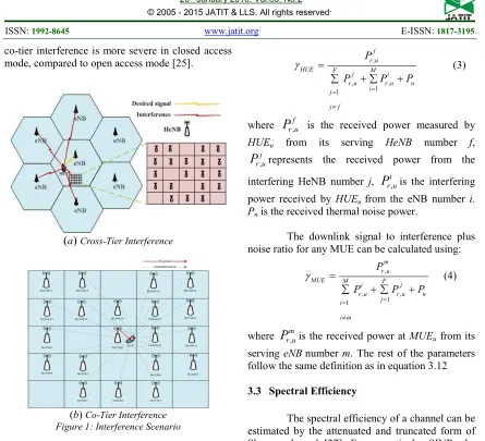
In the downlink, the received signal at the HUE contains the OFDMA transmitted symbols of the serving base station plus the interference induced by nearby femto and macro base stations [23]. Figure 1 shows the interference scenario used in this study. Two types of interference are considered:
(i) Cross-tier interference: occurs among the elements of different tiers of the network. For example, a HeNB causes interference to the downlink of MUE nearby [24] as shown in Figure 1(a).
(ii) Co-tier interference: occurs between network elements that belong to the same tier. In this case, it is the interference caused by a femtocell to another femtocell user [24] as shown in Fig. 1(b).
ISSN: 1992-8645 www.jatit.org E-ISSN: 1817-3195 co-tier interference is more severe in closed access
mode, compared to open access mode [25].
(
a)
Cross-Tier Interference [image:4.612.86.531.53.458.2](b) Co-Tier Interference Figure 1: Interference Scenario
3.2 Propagation and SINR Models
In this study, the 3GPP LTE-Advanced path loss models for urban deployments have been adopted [30], in which the path loss between the eNB and the UE is calculated as follows:
(outdoor UE)
(indoor UE) 10
macro
10 ow
15.3+37.6log R PL (dB)=
15.3+37.6log R+L
(1)where, R is the distance between the UE and eNB in meters and Low is the penetration loss of an outdoor wall, which is 20 dB.
The path loss between HeNB and UE within or outside an apartment for 5×5 grid scenario is calculated by using:
( )
femto 10 R
PL (dB) = 127 + 30log
1000 (2)
The received downlink signal to interference plus noise ratio of the HUE with a group of F femtocell BSs and M macrocell BSs can be expressed as [26]:
,
, ,
1 1
f r u
HUE F M
j i
r u r u n i
j
j f P
P P P
γ
= =
≠ =
+ +
∑ ∑
(3)
where
P
r u,f is the received power measured byHUEu from its serving HeNB number f,
, j r u
P
represents the received power from theinterfering HeNB number j,
P
r ui, is the interferingpower received by HUEu from the eNB number i. Pn is the received thermal noise power.
The downlink signal to interference plus noise ratio for any MUE can be calculated using:
,
, ,
1 1
m r u
MUE M F
i j
r u r u n j
i
i m P
P P P
γ
= =
≠ =
+ +
∑ ∑
(4)
where
P
r um, is the received power at MUEu from itsserving eNBnumber m. The rest of the parameters follow the same definition as in equation 3.12
3.3 Spectral Efficiency
The spectral efficiency of a channel can be estimated by the attenuated and truncated form of Shannon bound [27]. For a particular SINR, the spectral efficiency can be determined by the following:
[
]
max
min
min max
max
Thr =0 SINR < SINR
Thr = α .S(SINR)
SE bps / Hz SINR SINR < SINR
Thr =Thr SINR > SINR
<
=
(5)
where, S(SINR) = log2(1+SINR) is Shannon bound,
α is the attenuation factor, SINRmin and SINRmaxare the minimum and maximum SINRs supported by the available AMC scheme. Thrmax is the maximum spectral efficiency. The parameters α, SINRmin, SINRmax and Thrmax are set to 0.6, -10 dB, 23 dB and 4.4bps/Hz in this study [27].
3.4 Traffic Model
ISSN: 1992-8645 www.jatit.org E-ISSN: 1817-3195 distributions might be used in some simulation
scenarios.
Table 1: Different type of services.
Service Rate Requirement Ratio
VoIP 64 kbps 10%
Data [512-2000] kbps 40%
Web ≥ 64 kbps 50%
4. PROPOSED POWER CONTROL
SCHEME
The basic requirement for a HeNB is to provide a strong enough signal for its HUEs. On the other hand, the transmit power should not be too high, as to create strong interference to the neighbouring femtocells or MUEs.
4.1 Analytical Model
In this paper, a distributed HUE-assisted based power control scheme is proposed. The transmit power (Ptx) is adjusted according to the location of the HUE in the femtocell coverage area as in (6):
tx tmax tmin tmax
f
K
R
d
P = min max P × ,P ,P
(6)
where, d is the distance between the HUE and HeNB. Rf is the radius of the femtocell. Ptmax, Ptmin are the maximum and minimum transmitting power of HeNB, respectively. Ptmin depends on the SINR target related to the QoS requirements of the HUE.
K is an exponent that controls the dynamic range of power control.
However, it is more convenient and practical to estimate the parameter d from the reported path loss between HUE and the corresponding HeNB, without acquiring HUE position information. The path loss can be given as follows:
( ) 10( ) σ
PL = x f + Nlog d + x (7) where x(f) represents the dependence of the path loss on the frequency. N is a coefficient related to the type of environment. xσ denotes the shadow fading, is a Gaussian random variable with zero mean σ2 variance.
The distance (d) can be expressed as an exponential function:
( )
1
× PL- x(f)- x N
d = 10 σ (8)
This can be written as:
UE
1 N×Ρ
d = 10
(9)
Considering (9), the formula (6) can be modified in the following manner:
(UE max)
K 1
× -N
tx tmax tmin tmax
P = min max P × 10 ,P ,P Ρ Ρ
(10)The Ptmin is calculated to guarantee the target SINR of the HUE. Furthermore, the path-loss is partially compensated [28] as in (11):
(
)
(
tar serv serv t, max_HeNB tmin_HeNB)
tmin + + ,
P =max min SINR I αPL P P (11) where, Iserv is the average link interference, PLserv is the path-loss between HUE and the serving HeNB, α is a fractional compensation parameter between 0 and 1. Note that if α=1, then the full path-loss compensated. Ptmin_HeNB is the minimum allowed power that is transmitted by HeNB, which is set to 0 dBm as in 3GPP standard [30].
The fractional compensation parameter (α) is set adaptively based on the target SINR
according to:
, ,
, ,
1 - cur i
cur tar tar i tar i cur tar cur i if if γ γ γ γ α γ γ γ γ < = > (12)
where γcur,i is the current value of SINR for the femtocell user number i, and γtar,i is his target SINR.
4.2 Algorithm Description
This algorithm is to be executed in each HeNB individually to find the suitable power level that guarantee QoS requirements for each HUE (In this simulation the HUE SE is considered as the QoS criterion). The proposed algorithm is described in details below:
1. The HeNB collects the information fed back by the HUEs within its transmission range. Based on this information the HeNB determines whether the newly attached HUE is the furthest among the whole attached HUEs. Thus, the power control will be triggered.
2. To perform the power control, firstly the target SINR (γtar) of the HUE is calculated based on
ISSN: 1992-8645 www.jatit.org E-ISSN: 1817-3195 the γtar and the fractional pathloss
compensation parameter α is calculated according to equation 12. Based on these parameters the minimum transmit power level is determined according to equation 11. 3. The femtocell base station will make a
decision based on based on the values of the current SINR and the target SINR of the HUE.
a. If the current SINR is less than the target SINR then the transmit power will be updated based on equation 10.
4. Otherwise, the HeNB should be powered down by a step of ΔPtx.
5. In each HeNB a counter is used to count the number of transmit power updates during a certain period. If the HeNB transmit power is not updated then a periodical update is triggered regardless of the attachment of a new user and the counter is reset to zero. Then the power control will be executed with the same procedure as when a new HUE is attached.
The algorithm for the proposed dynamic scheme is shown in the following pseudo code:
Algorithm of the proposed scheme
1: forFnumber of activeHeNB
2: ifi=1:n HUE get active in under HeNB
3: ifk1 is the distance from the Fth HeNB to HUEnew
4: calculate γtar and α
5: calculate Ptmin based onγtar and α 6: ifγcur of HUE new < γtar
7: calculate power based on mathematical Eq.
8: increase the number of power updates by1
9: else if(γcur of HUE new > γtar) 10: reduce power by ΔPtx
11: increase the number of power updates by1
12: end if
13: else
14: break
15: end if
16: else
17: break
18: end if
19: each 10 Sec check the following
20: if no. of PWR updates=0
21: if γcur of HUE with distance k1< γtar 22: repeat step 7
23: else
24: repeat step 10
25: end if
26: else
27: reset the no. of PWR updates to zero
4.3 Simulation Scenario
The downlink macrocell/femtocell scenario as in Figure 1 is considered with seven eNBs at the centre of each macrocell. A typical 5×5 grid scenario of a dense urban area for femtocells with 25 houses, whereby each house has the size of 10m×10m is located at the edge of the centered macrocell (Fig.1). Twenty HeNBs are located randomly and uniformly in the houses. The closed access method is considered for HeNBs. This means only closed subscriber group (CSG) is allowed to connect to the femtocell, which is a preferred access mode by the residential owners that subscribe femtocell service. MUEs are randomly distributed with 15% indoor and the HUEs are located indoor within the coverage area with a specified minimum separation from their serving base station. A random waypoint model is used in characterizing the mobility of the users. The HUEs move with a velocity of 1 m/s, i.e. at pedestrian speed. Table 2 shows the main simulation parameters for both eNB and HeNB, which confirmed with 3GPP TR 36.814 [29]. Matlab is used to simulate the system.
Table 2: Simulation Parameters.
eNB
Parameter Typical value
Cell Radius 500 m
Bandwidth 20 MHz
Carrier Frequency 2000 MHz
Antenna Gain 14 dBi
eNB transmit power 46 dBm
Log-normal shadowing standard deviation
8 dB
Thermal noise density -174 dBm/Hz
Penetration Loss 20 dBm
Minimum distance between UE and cell
>= 35 m
HeNB
Parameter Typical value
Cell Radius 10 m
Bandwidth 20 MHz
Carrier Frequency 2000 MHz
Antenna Gain 5 dBi
HeNB transmit power 20 dBm
Log-normal shadowing standard deviation
10 dB
Thermal noise density -174 dBm/Hz
Antenna pattern Omnidirectional
ISSN: 1992-8645 www.jatit.org E-ISSN: 1817-3195
5. RESULTS AND DISCISSION
The main purpose of the power setting is to maintain the HUE coverage, throughput and to mitigate the co/cross-tier interference experienced by the neighbouring UEs. In this system level simulation, the performance of the power control approach in reducing the outage probability of MUEs is investigated. The outage probability of MUEs is defined as the ratio of MUEs who’s SINR is bellow -6 dB to the total number of MUEs [27].
[image:7.612.323.517.160.326.2]Figure 2 shows the average MUE outage probability for three different scenarios. From the results, it is obvious that the proposed dynamic scheme with adaptive fractional compensation parameter α outperforms the other two schemes. A reduction of 23% in the outage probability is achieved compared to the baseline scenario with maximum fixed transmit power (20 dBm) where the interference induced by the femtocell on the MUE should be severe. Furthermore, the proposed dynamic scheme appears to be more effective in mitigating the cross-tier interference rather than the static scheme with fixed fractional compensation parameter α = 1; where only a 5.5% outage reduction is obtained compared to baseline scenario
Figure 2: Average Outage Probability of MUEs
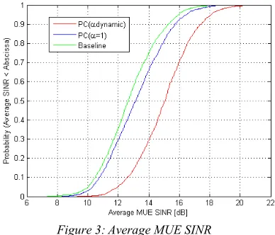
The results for the average MUE SINR are presented in Figure 3. From the results SINR gains of 0.56 dB and 2.45 dB are obtained by deploying the proposed dynamic scheme and the proposed static scheme respectively compared to the baseline scenario. It is apparent that the MUEs get the poorer received signal from the macrocell when using the fixed maximum transmit power in the baseline scenario for the HeNBs, where the highest interference is received from the CSG femtocells especially by the cell-edge MUEs. However, the
proposed dynamic scheme with adaptive fractional pathloss compensation has succeeded in improving the received signal for the MUEs by mitigating the cross-tier interference from femtocells, which result in more SINR gain.
Figure 3:Average MUE SINR
The average HeNB transmit power for static and dynamic schemes are shown in Figure 4. The results illustrate that by properly selecting the HeNB transmit power level using the proposed dynamic scheme with adaptive α; a remarkable power reduction of 45.5% (from 18.35 dBm to 10 dBm) is accomplished, in comparison to the static scheme with α = 1. Comparing to the baseline scenario where the HeNB transmits at a fixed maximum power of 20 dBm, a power saving of 10 dBm is gained by using the proposed dynamic scheme. Although femtocells are low powered base stations, these power savings are crucial for green deployment of femtocells; especially for dense deployment of femtocells that would result in increasing the total network consumption as millions of femtocells are expected to be deployed in the next few years.
[image:7.612.101.295.421.573.2] [image:7.612.322.505.561.709.2]ISSN: 1992-8645 www.jatit.org E-ISSN: 1817-3195 By reducing the HeNB transmit power to
[image:8.612.320.519.74.257.2]50% using the proposed dynamic scheme comparing to the baseline scenario, a remarkable drop in the HUE SINR is expected. However, the results in Figure 5 show that minor reduction on HUE SINR (0.95 dB) occurs when using the proposed dynamic scheme. In this simulation, a 5×5 grid scenario for femtocells is used, in which short distances between the neighbouring femtocells exist. Thus, the co-tier interference between femtocells increases. Since the femtocells are located at the edge of the macrocell in this simulation, the co-tier interference is more critical. By setting the HeNB transmission power according to the location of the HUE inside the femtocell; the co-tier interference between femtocells could be reduced. However, adaptive fractional pathloss compensation helps to achieve more co-tier interference mitigation. That explains the maintaining of good HUE SINR level, despite the huge reduction in the transmit power.
Figure 5: Average SINR of HUE
the proposed dynamic scheme with adaptive fractional pathloss compensation, sets the minimum transmit power level of the HeNB adaptively based on the target SINR of the HUE that would guarantee the minimum data rate required by its type of service. As shown in Figure 6 the HUE spectral efficiency is still maintained when using the proposed dynamic scheme despite the reduction of HeNB transmit power; with a slight decrement of 5.27% compared to the baseline scenario. On the contrary, a degradation of 22.68% occurs in the HUE SE when using fixed minimum transmit power level of 0dBm; as in this scenario the HeNB transmit power would be powered down without constraint that considers the QoS requirements of the femtocell users.
Figure 6. Average Spectral Efficiency of HUEs
The baseline scenario provides the worst performance of MUEs in terms of outage probability as shown in Figure 7. By using the proposed dynamic scheme with adaptive minimum transmit power a remarkable reduction in the outage probability of MUEs is achieved. However, more HeNB power reduction could be obtained by using the fixed minimum transmit power. Hence, more cross-tier interference could be minimized, which in turn will incur less MUE outage. Furthermore, by minimizing the aggregated interference, more SINR gains could be achieved. Thus, the scenario with fixed minimum transmit power could achieve more enhancement in MUE SINR. However, this enhancement is at the cost of the performance of HUEs as illustrated in the previous results (Fig. 6). Therefore, proposed dynamic scheme with adaptive minimum transmit power appears to provide a better compromise between the performance of MUEs and HUEs.
Figure 7.Average MUE Outage for Adaptive Ptmin, fixed
[image:8.612.100.293.350.514.2] [image:8.612.322.518.525.679.2]ISSN: 1992-8645 www.jatit.org E-ISSN: 1817-3195
6. CONCLUSION
In this paper, a power control scheme based on HUE measurements is proposed. The transmit power of the HeNB is adjusted based on the location of the HUE in the femtocell. However, the location is estimated based on the path loss measurements of the HUE to eliminate the complexity of using positioning techniques. Furthermore, the minimum level of power transmission is constrained to the target SINR that is set according to the required HUE QoS. In addition, the minimum transmit power is calculated based on fractional compensation for the path-loss, which helps more in mitigating the interference to the neighbouring cells. The system level simulation results show that the proposed scheme has reduced the outage probability for the MUEs. Moreover, minimizing the transmit power, according to the position of HUE helps to reduce the power consumption for greener deployment of femtocells, while conserving good performance for the HUEs in terms of SE. Thus, the proposed dynamic scheme has provided better compromise between the performance of MUEs and HUEs.
ACKNOWLEDGMENT
This research was supported by Universiti Kebangsaan Malaysia under grant GUP-2014-005.
REFRENCES:
[1] R. Thakur, A. Sengupta, and C. Siva Ram Murthy, “Improving Capacity and Energy Efficiency of Femtocell Based Cellular Network through Cell Biasing” 11th International Symposium on Modeling & Optimization in Mobile, Ad Hoc & Wireless Networks (WiOpt), 2013, pp. 436-443.
[2] V. Chandrasekhar, J.G. Andrews, and A. Gatherer, “Femtocell networks: a survey,” IEEE Communications Magazine, vol. 46, issue: 9, Sep 2008, pp. 59–67.
[3] 3GPP TS 36.300 “Evolved Universal Terrestrial Radio Access (E-UTRA) and Evolved Universal Terrestrial Radio Access Network
(E-UTRAN),” v11.0.0, 2012.
[4] M. F. Khan, m. I. Khan, and K. Raahemifar, “A Study of Femtocell Architectures for Long Term Evolution (LTE)-Advanced Network,” in
Proc. CCECE Conf. , 2011, pp. 000817-000821.
[5] P. Lin, J. Zhang, Y. Chen, and Q. Zhang, “Macro-femto heterogeneous network deployment and management: from business models to technical solutions,” IEEE Tras. Wireless Communication, vol. 18, issue: 3, June 2011, pp. 64-70.
[6] A. Aijaz, H. Aghvami, and M. Amani, “A Survey on Mobile Data Offloading: Technical and Business Perspectives” IEEE Tras. Wireless Communication, vol. 20, issue: 2, 2013, pp. 104-112.
[7] P. Xia, V. Chandrasekhar, and J. G. Andrews, “Open Vs. Closed Access Femtocells in the Uplink” IEEE Tras. Wireless Communication, vol. 9, issue: 12, 2010, pp. 3798-3809.
[8] Afaz Uddin Ahmed, Mohammad Tariqul Islam, Mahamod Ismail, and Mohammad Ghanbarisabagh, “Dynamic Resource Allocation in Hybrid Access Femtocell Network,” The Scientific World Journal, vol. 2014, Article ID 539720, 7 pages, 2014. doi:10.1155/2014/539720.
[9] S-P. Yeh, S. Talwar, N. Himayat, and K. Johnsson, “Power Control Based Interference Mitigation in Multi-Tier Networks,” in Proc. IEEE GLOBECOM Workshop, 2010, pp.701-705.
[10]S. Al-Rubaye, A. Al-Dulaimi, J. Cosmas, “Pilot Power Optimization for Autonomous Femtocell Networks” in Proc.Wireless Advanced (WiAd),pp. 170-175.
[11]T. Zahir, K. Arshad, A. Nakata, and K. Moessner, “Interference Management in Femtocells” IEEE Communications Surveys & Tutorials, vol. 15, issue:1, 2013, pp. 293-311. [12]S. A. Saad, M. Ismail, and R. Nordin, “A
Survey on Power Control Techniques in Femtocell Networks”Journal of Communications, vol.8, no.12, Dec. 2013, pp. 845-854.
[13]Lina S. Mohjazi, Mahmoud A. Al-Qutayri, Hassan R. Barada, Kin F. Poon, and Raed M. Shubair, “Self-Optimization of Pilot Power in Enterprise Femtocells Using Multi objective Heuristic,” Journal of Computer Networks and Communications, vol. 2012, Article ID
303465, 14 pages, 2012.
doi:10.1155/2012/303465.
ISSN: 1992-8645 www.jatit.org E-ISSN: 1817-3195 [15]H. Claussen, L.T.W. Ho, “ Dynamic Idle
Mode Procedures for Femtocells,” Bell Labs Tech. J., vol. 15,no 2, Sept. 2010 pp. 95-116. [16]M. S. Jin, S. A. Chae, and D. I. Kim, “Per
Cluster Based Opportunistic Power Control for Heterogeneous Networks,” ,” Proc. IEEE 73rd Vehicular Technology Conference (VTC) , 2011, p.p. 1-5.
[17]K-T. Cho, J. Kim, G. Jeon, B. H. Ryu, and N. Park, “Femtocell Power Control by Discrimination of Indoor and Outdoor Users,”
Proc.IEEE Wireless Telecommunications Symposium (WTS),2011, pp.1-6.
[18]K-J. Tsao, S-C. Shen, and T-C. Hau, “Location-Dependent Power Setting for Next Generation Femtocell Base Stations,”
Proc.IEEE Wireless Communication and Networking Conference (WCNC) , 2011, pp. 767-772.
[19]T. Akbudak, and A. Czylwik, “Distributed Power Control and Scheduling for Decentralized OFDMA Networks,” in Proc. International ITG Workshop on Smart Antenna, Feb. 2010, pp. 59-65.
[20]S-P. Yeh, S. Talwar, N. Himayat, and K. Johnsson, “Power Control Based Interference Mitigation in Multi-Tier Networks,” in Proc. IEEE GLOBECOM Workshop, 2010, pp.701-705.
[21]Z. Wang, W. Xiong, C. Dong, J. Wang, and S. Li, “A Novel Downlink Power Control Scheme in LTE Heterogeneous Network,” Proc. IEEE International Conference on Computational Problem-Solving (ICCP) , 2011, PP.241-245. [22]P. Tarasak, S.E. Nai, and F. Chin, “Location
Based Transmit Power Control for Femtocell Access Points,” Proc. IEEE International Conference on Communications (ICC) , 2012, PP.6840-6844.
[23]F. Mhiri, K. Sethom, and R. Bouallegue, “A Survey on Interference Management Techniques in Femtocell Self-Organizing Networks,” Journal of Network and Computer Apllications, vol. 36, no. 1, Jan. 2013, pp. 58-65.
[24]A. U. Ahmed, M. T. Islam, and M. Ismail, "A Review on Femtocell and its Diverse Interference Mitigation Techniques in Heterogeneous Network," Wireless Personal Communications, 2014, pp. 1-22.
[25]T. Zahir, K. Arshad, A. Nakata, and K. Moessner, “Interference Management in
Femtocells,” IEEE Communications Surveys & Tutorials, vol. 15, no.1, Feb 2013, pp.293-311. [26]M. Yavuz, F. Meshkati, S. Nanda, A.
Pokhariyal, N. Johnson, B. Raghothaman, et al., "Interference management and performance analysis of UMTS/HSPA+ femtocells," IEEE Communications Magazine, vol. 47, 2009, pp. 102-109.
[27]3GPP tech. rep. 36.942, v.11.0.0, Sept. 2012. [28]3GPP TSG RAN WG1 R1-073035, Intra-cell
Uplink Power Control for EUTRA, 3GPP std., Orlando, US, Jun. 2007.
[29]3GPP tech. rep. 36.814, v.9.0.0, Mar. 2010. [30]X. Xu, G. Kutrolli and R. Mathar, “Energy