849
BREAKPOINT MATCH TRACING- A NEW METHOD FOR
THE THREE DIMENSIONAL RECONSTRUCTION OF
REGIONAL TECTONICS
1PENGHAO WANG, 2LIANGJIE TANG
1State Key Laboratory of Petroleum Resource and Prospecting, China University of Petroleum, 102249,
Beijing, China
2Basin & Reservoir Research Center, China University of Petroleum, 102249, Beijing, China
ABSTRACT
The method of breakpoint-match-tracing is a new numerical simulation one to reconstruct the fault deformation process in three-dimensional space. This method, however, based on the spatial data relationship of three dimensional geological bodies, will reconstruct their original relationship result from using match path to trace the breakpoint and computation. Through picking up the breakpoint in any fault surface and considering as the research object, and defining the sets of breakpoint as the reconstruction path for the hanging-wall and footwall, this method will provide the boundary condition for the tectonic deformation. The regional fault blocks would be concurrently reconstructed combining with the Mass-Spring Equation and use it to be as parallel computation. In this paper, the three dimensional tectonic reconstruction and simulation for the branched faults of Archean top, distributed in Bohai Bay Basin, were achieved using this method, and the geometric shape for the different stages and the corresponding analysis related to the whole deformation procedure were all also discussed. Taking the tectonic deformation stage as the model output node, aimed at vividly reconstructing the geometric configuration of fault and fault block, and thus the whole tectonic deformation can be fully analyzed during the whole tectonic deformation procedure.
Keywords: Match Tracking Method, Tectonic Restoration, Parallel Calculating
1.
INTRODUCTIONIn recent years, tectonic deformation restoration has got attention from numerous scholars as the a hotspot of structure research[1, 2]. Along with the development of computer aided mapping, many studies has been carried out in the field of tectonic deformation restoration[3~5]. With the extensive usage and wide application of three dimensional geological modeling software, complex tectonic problems were put forward, such as, displacement changes obviously along strike, irregular movement and synchronous movement of fault blocks. Thus it can be seen that two-dimensional equilibrium profile can not meet the analysis of regional tectonic deformation under three dimensional environment[6~9]. How to carry out synchronous deformation to fault activities of same tectonic background under three dimensional environment, regarding the fault activities as integrated movement. Taking this as the research content of this paper, branch faults typically developed in Bohai Bay Basin and strata model of Bohai Bay Basin are selected to carry out numerical
simulation, build the tracking path with the aid of matching relationship of hanging wall and footwall, parallel calculate is proceeded to conduct deformation simulation, achieving the aim of synchronization restoration of multiple faults.
850
2.
INTRODUCTION OF FAULT MODELAND BREAKPOINT MATCH TRACKING METHOD
Breakpoint match tracking method is a kind of method to restore original geometry of faults in three dimensional with geometrical topological operation. This method assumes the spatial position and geometry of footwall of main fault is fixed, fault deformation is just the deformation of hanging wall and secondary branch fault. By defining the breakpoint matching relationship of hanging wall and footwall, breakpoint of hanging wall actively track the breakpoint of footwall. With the aid of spatial position change and motion path of breakpoint of hanging wall, drive the deformation of corresponding fault area, complete the change of spatial position of fault block while eliminate displacement, achieving the aim of three dimensional fault restoration.
Corresponding mathematics content of breakpoint match tracking relations is: spatially, define different fault blocks and fault plane as independent set, breakpoints of hanging wall and footwall as subset of the set, also the subset of corresponding fault plane. Pick up breakpoints of hanging wall and footwall to conduct selective correspond (match tracking), build motion path in fault set by corresponding relationship, then displacement process is fully contained in the fault plane set. With all the spatial points of active hanging wall set to form mass-spring simultaneous equations[12, 13], make the deformation to target location by parallel calculate, so as to complete the whole set transformation. This method can select multiple set at a time to conduct deformation at the same time, also can select multiple subset of one single set to conduct parallel deformation.
Footwall set
{
1 2}
:
,
mA
M M
L
M
(1)Breakpoint set of footwall
{
}
:
n,
n pa
M
L
M
+ (2)a
∈
A
Hanging wall set
{
1 2}
:
,
mB
N N
L
N
(3)Breakpoint set of hanging wall
{
}
:
n,
n pb
N
L
N
+ (4)b
∈
B
Data point set of fault plane
{
1}
:
,
n,
n,
n p,
n,
n pF
F
L
F N
L
N
+M
L
M
+ (5)Data set of match tracking1Fn
{
1}
1
:
n,
n,
2 n,
nP
N F
F
L
M
(6) Point set of corresponding space1 1 1
:
n p n p n p
F F F
M M M
F
x
y
z
x
+y
+z
+
M
M
M
(7)Regression equation of three dimensional spatial point set
1 2 2
1 2 0
( , ) p p p p
n n n
f x y =a x +a − x − +a − x − y + +L a y
[image:2.612.319.519.253.476.2]
(8)
Figure 1: Schematic Diagram Of Fault Match Tracking
Where an, an-1, an-2, a0 are the coefficients
calculated by plugging the known breakpoint of fault plane into the equation, the curve in fault plane determined by this equation can be considered as the path of breakpoint match tracking(Figure 1).
851
21 43 43
1 2 1
21 43 43
,
sl
l
l
l
l
f
k
c
f
f
l
•
= −
−
= −
•
(9)21 43 21
3 4 3
21 43 21
,
sl
l
l
l
l
f
k
c
f
f
l
•
= −
−
= −
•
(10)Where represent the cosine of vector and vector.
ks represent stiffness coefficient , this paper
select modulus of elasticity to replace it.
Mass-Spring method gives particle characteristics to adjacent data points and gives elastic properties to adjacent particles by aid of position of spatial data point. Through geometric changes of surface, independent movement mode of adjacent particles is built. By defining the elastic properties of particles, elements in spatial point set of fault are contacted with each other, achieving the aim of overall movement.
3.
NUMERICAL SIMULATION ANDDISCUSSION OF FAULT RESTORATION
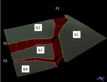
The software 3D move is used in this paper as model building tool, this software has the ability of spatial entity data modeling, and has the function of grid triangulation, can provide reliable model for follow-up study. Fault model in this paper comes from Liaoxi low swell of Bohai Bay Basin, the main fault (F1) develops in NNE direction, associated with two branch faults (F2, F3) in EW direction, depth data of top surface of Archean is selected as the surface of three dimensional model, frame of strata model and fault match tracking modeling is carried out on the basis of this(Figure 2).
[image:3.612.302.521.71.255.2]By observing the contact relationship of fault and the fault block and tectonic location among fault blocks, it is found that fault block B1 situates in footwall of fault F1, and does not participate in fault activities, therefore, data points of fault block B1 are fixed (similar to pin line in production method of equilibrium profile ) as the structure reference position. Take the horizontal surface of highest position of fault block B1 as reference plane of tectonic restoration, other blocks restore to the reference plane while eliminate displacement along fault plane. This process can be considered as the tectonic inversion from original unruptured geometry to nowadays structure geometry by structure deformation, tectonic deformation restoration is conducted under this logic.
Figure 2: Archean Top Surface Of Liaoxi Uplift In Bohai Bay Basin
The area within the yellow frame is the regional branch fault model of numerical simulation
Figure 3: Breakpoint Matching Relationship And Tracking Path Of Liaoxi Uplift In Bohai Bay Basin
3.1 Models and Parameters Calculation
[image:3.612.313.522.281.441.2]852 Table 1 : Parameters Of Numerical Simulation Of
Archean Top Surface In Bohai Bay Basin
Lithology Density Elastic Modulus
Poisson's Ratio Gneiss 2650kg/m3 69Gpa 0.110
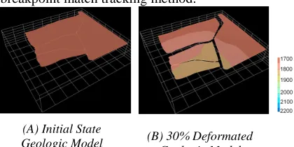
Assume that there is no initial displacement, and the horizontal situation is undeformed state, the corresponding deformation degree is 0%. This study selects 30%, 60% and 100% deformation degree of geological model respectively as comparison to analyze the displacement change and spatial position change of fault blocks during deformation.
3.2 Process Analysis And Discussion Of Rationality
Figure 4 represents the three dimensional geometry of fault in different deformation stages. Operation mode of tectonic deformation restoration: with aid of current tectonic geometry and related algorithm of deformation, restore the tectonic to initial undeformed state gradually. Original geometry is taken as the initial state in this paper from the point of tectonic deformation, deformation rule of branch faults which strike directions are significantly different and the rationality tectonic deformation are analyzed step by step.
3.2.1 Analysis of deformation process
By observing the entire deformation process, it is shown that about 233m of regional stretch in WE direction is mainly provided by fault F1. Because the fault block B1 is fixed, it can participate in the tectonic restoration only in vertical direction, all data points get back to reference plane by vertical projection, fault blocks B2, B3 and B4 to the west of fault F1 are stretched about 190m in NS direction along with the process of their westward movement, it is mainly provided by fault F2 and F3.
As the hanging wall of fault F1, fault block B2 is also the footwall of fault F2. Its deformation process is mainly controlled by fault F1, it moves to west along the fault plane of north part of fault F1, promote fault block B3 at the same time. As an independent hanging wall, fault block B2 participate in deformation of tectonic restoration only as a fault line (red), thus its deformation mode totally depends on match tracking path of fault plane of the north part of fault F1. By comparing tectonic position and tectonic geometry of fault block B2 during tectonic deformation Longitudinally, it is found that fault block B2 rotate clockwise in a certain extent while its westward horizontal movement. Take the southeast end of fault block B2 as axis to contrast the position before
and after deformation, fault block B2 rotate clockwise for 5 ° compare to initial state.
Fault block B3 is an independent tectonic unit, held in fault block B1, B2 and B4. It is stretched in two directions during tectonic deformation: westward extension from the middle part of fault F1 and southward extension from fault F2. Fault block B3 finally moves toward SW direction under extension of two directions. Because the westward displacement is bigger than the southward displacement, additionally, the horizontal displacement provided by fault F2 increases from east to west, result in the rotate of fault block B3 while horizontal displacement. Take the northeast end of fault block B3 as axis to contrast the position before and after deformation, fault block B3 rotate anticlockwise for 4 ° compare to initial state.
Fault block B4 is located in the southwest of research area, its deformation and displacement directly controlled by the fault F1 and fault F3, and indirectly affected by fault F2. The horizontal westward displacement is of about 220 m, southward displacement inherited the 118 m horizontal displacement of fault block B2 provided by fault F2, add the 70m displacement of fault F3, total displacement of fault block B4 is up to about 188m. Contrast the position change before and after deformation, fault block B4 also rotates in a certain extent while its horizontal movement: take the southwest end of fault block B4 as axis to contrast the position before and after deformation, fault block B4 rotate clockwise for 7 ° compare to initial state.
Because fault blocks are controlled by multiple faults, controlled by extension from different direction, the track of gross displacement change from simple line to complex curve, this is also the reason why the fault blocks rotate under the control of multiple faults. As to restoration of fault displacement in three dimensional model, fault displacement change obviously along the strike of the fault, such as the fault F1,F2 and F3 in this model, this problem can be handled effectively by breakpoint match tracking method.
(A) Initial State
Geologic Model (B) 30% Deformated
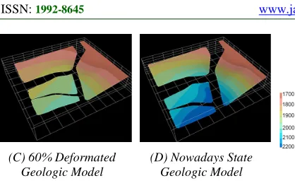
[image:4.612.313.523.613.718.2]853 (C) 60% Deformated
Geologic Model
[image:5.612.90.299.75.208.2](D) Nowadays State Geologic Model
Figure. 4. Three Dimensional Models Of Archean Top Surface Of Different Restoration Stage
3.2.2 Discussion of deformation rationality
In this paper, the aim of deformation restoration is to restore the deformation to initial horizontal reference position while restore the displacement of fault. This proposal is based on the theory of two dimensional equilibrium profile, and applied in three dimensional geological model restoration, replace the two dimensional template line with three dimensional template line. This method is applicable to line length conservation and vertical simple shear theory of equilibrium profile in extensional area, corresponding to the Mass-Spring equation and vertical simple shear in this research. Breakpoint match tracking method is proposed in this paper, it provide complete deformation path, which picked up in the fault breakpoint of top surface of Archean, then build corresponding relationship. By adjusting elastic coefficient of the grid, Mass-Spring equation can ensure geometric stability of fault during deformation. Compare to line length conservation method which focus on result analysis, the advantage of Mass-Spring equation is the controllable process, it divides the deformation process of single fault into single set, through parallel calculate of geometric relation, balances the relative position relationship of faults. This theory can be used in equilibrium restoration of complex fault system under the condition of three dimensional environment and interactive attitudes. The change of spatial position and geometry during deformation. As the footwall of fault F1, fault block B1 is the reference position, it only participate in vertical deformation, and link the fault block B2, B3 and B1 during vertical deformation. Interrelated fault block B2 and B3 participated in parallel calculate is stable in geometry, synchronous in deformation process, and meet the given premise and aim, so the simulation results of deformation restoration is accepted.
4.
CONCLUSION1. Breakpoint match tracking method is a kind of three dimensional structure restoration method, applicable to surface tectonic restoration in complicate extensively faulted region. By picking up path of breakpoint match tracking, establish corresponding relationship of breakpoint of hanging
wall and footwall, restore the faulted surface to its original geometry. All faults are synchronously restored to reference plane by parallel calculate of position relationship among faults during the process of fault displacement restoration.
2. Different fault displacement along strike of fault can be effectively handled by breakpoint match tracking method. Process comparison, which is a new research direction, is given to tectonic restoration research, researchers can deeply analyze the matching relationship and restriction mechanism during the process of fault development on the basis of process comparison. Rotation of faults due to different activities of faults can also be solved by this method, using quantitative analysis in different stages.
REFERENCES:
[1] L. F. Mei, Z. Q. Liu, J. G. Tang, et al., “Mesozoic Intra-Continental Progressive Deformation in Western Hunan-Hubei Eastern Sichuan Provinces of China: Evidence from Apatite Fission Track and Balanced Cross- Section”,
Earth Science, Vol. 35, No. 2, 2010, pp.
161-167.
[2] G. S. Cheng, “A Study of the Balanced Sections of the Structure in the Central Part of Southern
Junggar Basin”, ACTA GEOSCIENTICA
SINICA, Vol. 29, No. 5, 2008, pp. 563-570.
[3] H. Su, L. P. Qu and G. X. Li, et al., “Balanced section and tectonic evolution in the Dongpu depression”, Oil Geophysical Prospecting , Vol. 35, No. 4, 2000, pp. 469-478.
[4] Z. X. Chen, D. Jia. Q. Zhang, et al, “Balanced Cross-section Anal ysis of the Fold—Thrust Belt of the Longmen Mountains”, ACTA
GEOLOGICA SINICA, Vol. 79, No. 1, 2005,
pp. 38-44.
[5] D. L. Liu, X. M. Fang, Y. D. Wang, et al., “Cenozoic deformation history determined by restoration of the balanced section across the Qaidam Basin”, Chinese Journal of Geology, Vol. 43, No. 4, 2008, pp. 637-647.
[6] D. P. Yan, T. C. Lu, L. P. Meng, et al., “Balanced Geological Section for Extensional Tectonic Basin and Its Implication: An Example from Southern Songliao Basin”, Earth Science, Vol. 28, No. 3, 2003, pp. 275-280.
[7] D. Kossow, C. M. Krawczyk, “Structure and quantification of processes controlling the evolution of the inverted NE-German Basin”,
Marine and Petroleum Geology, Vol. 19, No. 1,
854 [8] P. E. Kraemer, “Orogenic shortening and the
origin of the Patagonian orocline (56°S.Lat)”,
Journal of South American Earth Sciences, Vol.
15, No. 3, 2003, pp. 731-748.
[9] N. McQuarrie, “Crustal scale geometry of Zagros fold-thrust belt,Iran”, Journal of Structure
Geology, Vol. 26, No. 3, 2004, pp. 519-535.
[10] G. Paul, S. Jones, N. Salter, “A new technique for 3-D flexural-slip restoration”, Journal of
Structure Geology, Vol. 24, No. 1, 2002, pp.
773-782.
[11] S. Grelaud, W. Sassi, N. Salter, “Dominique Frizon de Lamotte. Kinematics of eastern Salt Range and South Potwar Basin (Pakistan): a new scenario”, Marine and Petroleum Geology, Vol. 19, No. 1, 2002, pp. 1127-1139.
[12] D. Baraff, A. Witkin, “Large Steps in Cloth Simulation”, Proceedings of ACM Siggraph, 1998, pp. 43-54.
[13] M. Desbrun, P. Schröder, and A. Barr, “Interactive animation of structured deformable objects”, Proceedings of the 1999 conference on
Graphics interface, 1999, pp. 11-18.