© 2016, IRJET | Impact Factor value: 4.45 | ISO 9001:2008 Certified Journal | Page 819
VIRTUAL ANALYSIS OF COMPOSITE MATERIAL LEAF SPRING
Pradeesh A. R.
1; Sudeesh S
2; Mubeer M.P
3; Sadanandan R
4; Philip George
5;
Nanditha Muralidharan
61, 2, 3, 4, 5, 6
Asst. Professor, Dept. of Mechanical Engineering, Ammini college of Engineering, Palakkad-678613
---***---Abstract—Structural analysis of leaf spring using
different composite materials in light commercial
vehicle. Leaf springs are unique kind of springs used in
vehicle suspension systems. The benefit of leaf spring
over helical spring is that the ends of the spring may be
guided along a definite path as it deflects to act as a
structural member in addition to energy absorbing
machine. The main function of leaf spring is not only to
bear vertical load but also to isolate road induced
vibrations. A typical leaf spring configuration of
TATA-ACE light commercial vehicle is chosen for study. Finite
element analysis has been carried out to find out the safe
stresses and pay loads. The prologue of composite
materials has made it likely to diminish the weight of the
leaf spring without any diminution in load carrying
capability and stiffness. Leaf spring is modeled in CATIA
V5 R20 software and it is imported in ANSYS workbench
14.5. The conventional steel leaf spring and the
composite leaf spring were examined under parallel
conditions using ANSYS software and the outcome are
Stresses, deflection and strain energy results for both
steel and composite leaf spring material were obtained..
Key Words: composite materials, leaf spring, steel, stresses, deflection.
1. INTRODUCTION
A leaf spring is a plain type of spring generally used for
the suspension in wheeledautomobiles. Initially called a
laminated or carriage spring, and occasionally referred to as a semi-elliptical spring or cart spring, it is one of the oldest
types of springing, dating back to medieval times.
The shape of leaf spring is the form of a slender arc-shaped
length of spring steel of rectangular cross-section. In the most
general pattern the center of the arc provides location for the axle, either end for joining to the automobile body is
provided with tie holes. For weighty vehicles, a leaf spring can be made from several leaves piled on top of each other in several layers, often with progressively smaller leaves. Leaf springs can serve locating and to some extent damping as
well as bouncing purposes. While the interleaf friction provides a damping action, it is not well controlled and results in stiction in the motion of the suspension. For this
reason some companies have used mono-leaf springs.
A leaf spring can either be joined directly to the frame at both
ends or attached directly at one end, usually the front, with the other end joined through a shackle, a short swinging arm. The shackle takes up the leaning of the leaf spring to stretch when compressed and thus makes for flexible springiness. To carry a swiveling member some springs terminated in a concave end, called a spoon end.
Finite Element analysis tools offer the marvelous advantage of enabling design teams to consider essentially any casting option without incurring the expenditure associated with built-up and machine time. The capability to try new designs or models on the computer gives the chance to reduce problems before initiating production. Additionally, designers can rapidly and with no trouble find out the sensitivity of specific molding constraints on the quality and production of the ultimate part. The leaf spring replica is formed by CatiaV5R20, pro-E or any of the modeling software and it is imported in to the analysis software and the boundary conditions, the loading conditions are given to the imported model and result are calculated by post processor. The results of steel leaf spring and composite leaf spring are obtained to forecast the advantages of composite leaf spring for an automobile.
© 2016, IRJET | Impact Factor value: 4.45 | ISO 9001:2008 Certified Journal | Page 820
bump etc. The leaf springs are more influenced due to fatigueloads, as they are a part of the unstrung mass of the vehicle..
2. MATERIALS
The materials commonly used for designing a leaf spring are, chromium vanadium steel, chromium-nickel-Molybdenum steel, plain carbon steel, silicon-manganese steel. The materials selected for steel leaf spring is 65Si7.
Table -1: STEEL (65SI7)
Density(ρ) Kg/m3) 7860
Young’s modulus, Mpa 2.1e5
Poisons ratio 0.266
Tensile strength (Mpa) 500 Tensile ultimate strength
(Mpa) 800
2.1 Composite Materials
A composite material is defined as a material created of two or more ingredients combined on a macroscopic level by mechanical and chemical bonds. Composites are mixture of two substance in which one of the substance is known as the matrix phase is in the form of sheets, fibers, or particles and is implanted in the other substance say the reinforcing phase. Numerous composite materials propose a combination of strength and modulus that are either equivalent to or superior than any conventional metallic metals. Modulus to weight-ratios and the strength to weight-ratio of these composite materials are markedly higher to those of metallic materials Because of their low specific gravities. Fatigue damage tolerances and the fatigue strength weight ratios of several composite laminates are exceptional. For these explanations, fiber composite have emerged as a main class of structural substance and are either used or being considered as replacements for metal in many weight-critical parts in automotive, aerospace, and other industries. High internal damping capacity is another unique feature of numerous fiber reinforced composites. This leads to enhanced vibration energy inclusion within the material and results in reduced transmission of noise to adjacent structures.
Table -2: carbon fiber/E-poxy material properties: S.
N Properties Valve
1 Tensile modulus along
X-direction(EX), Mpa 62000
2 Tensile modulus along
Y-direction(EY), Mpa 48000
3 Tensile modulus along
Z-direction(EZ), Mpa 48000
4 Tensile strength of the material,
Mpa 1830
5 Shear modulus along
XY-direction(Gxy),Mpa 3270
6 Shear modulus along
YZ-direction(Gyz),Mpa 3270
7 Shear modulus along
ZX-direction(Gzx),Mpa 1860
8 Poisson ratio along
XY-direction(NUxy) 0.22
9 Poisson ratio along
YZ-direction(NUyz) 0.22
10 Poisson ratio along
ZX-direction(NUzx) 0.30
11 Mass density of the material
[image:2.595.303.531.391.544.2](ρ),Kg/mm3 1580
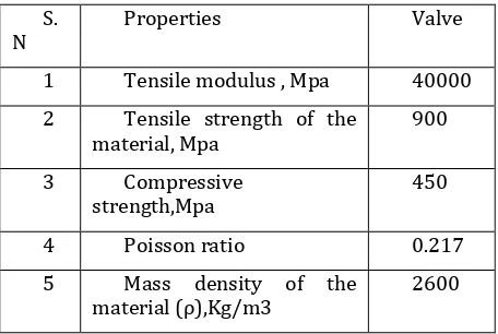
Table -3: Material properties of E-glass /E-poxy S.
N Properties Valve
1 Tensile modulus , Mpa 40000 2 Tensile strength of the
material, Mpa 900
3 Compressive
strength,Mpa 450
4 Poisson ratio 0.217
5 Mass density of the
material (ρ),Kg/m3 2600
AlBeMet (Beryllium aluminum):
AlBeMet is the trade name for
a beryllium and aluminum metal matrix composite derived by a powder metallurgy process.
AlBeMet is produced by hot consolidating gas atomized prealloyedfine particles. Each powder particle includes aluminum between beryllium dendrites producing a homogeneous microstructure. Aluminum-beryllium metal matrix composite merged the fabrication and mechanical property behaviors of aluminum with the high modulus and low density characteristics of beryllium.
In aerospace and satellite applications Be-Al alloys are used due to weight advantage.
© 2016, IRJET | Impact Factor value: 4.45 | ISO 9001:2008 Certified Journal | Page 821
AlBeMet have High modulus-to-density ratio 3.8 timesthat of aluminum or steel reduces the chance of mechanically induced failure and minimizes flexure.
Thermal conductivity of just about 210 W/mK exceed by about 25% that of general aluminum metal matrix composites such as Al 6061.
[image:3.595.313.551.58.412.2]The composite structure of Polished AlBeMet displays considerable surface scatter inherent and it cannot be removed by optical polishing. (Usual surface roughness from an AlBeMet polished surface is in the 200-250 angstroms finish.) An amorphous coating such as electro less nickel is essential.
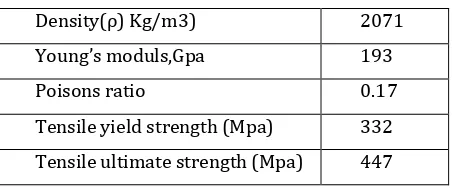
Table -4: AlBeMet
Density(ρ) Kg/m3) 2071
Young’s moduls,Gpa 193
Poisons ratio 0.17
Tensile yield strength (Mpa) 332 Tensile ultimate strength (Mpa) 447
3. DESCRIPTION
Static Analysis Used to determine displacements stresses, etc. under static loading conditions linear static analyses. Nonlinearities can include hyper elasticity, contact surfaces, stress stiffening, plasticity, large deflection, large strain and creep.
The leaf spring modeled in CATIA V5 R20 was imported to ANSYS in IGES format. Leaf spring was modeled as a solid part, SOLID187 solid element was used to mesh the model. SOLID187 element is10-node and higher order 3-D element. SOLID187 has a quadratic displacement behavior and is well suited to modeling irregular. The element is defined by 10 nodes having three degrees of freedom at each node: translations in the nodal x, y, and z directions. The SOLID187element has creep, stress stiffening, plasticity, hyper elasticity, large deflection, and large strain capabilities; the element input data also includes the orthotropic or anisotropic material properties.
TATA ACE light commercial vehicle: GVW (weight) = 1550 kg
Maximum load capacity= 1000 kg Total weight = 2550 kg
In single leaf = 25015.5 /4 = 6253.875 N Span length 2L = 1540 mm
Uniform width leaf spring equation
Uniform width leaf spring:
E – The modulus of elasticity
L – The characteristic length of the spring. F – Force applied to leaf spring
b - Width of leaf spring
h - Height or thickness of leaf spring
Length of Leaf Spring Leaves:
The length of the leave springs are calculated by using the formulas given below. n = 5
Length of (n-1) the leaf = (Effective length /n -1) *(n-1) +Ineffective length
Where 2L1 = Length of span or overall length of the spring,
l=distance between centers of U-bolts (ineffective length (I.L) of the leaf spring),
nF= Number of full length leaves, nG = Number of graduated leaves, n = Total number of leaves = nF + nG,
E.L = Effective length of the spring = 2L1 – (2/3) l, d = Inside diameter of eye and
t = Thickness of master leaf.
Table -5: Geometric properties of leaf spring: S
l.No .
Parameters Dimensions
(mm)
1 Total length of spring (eye to eye)
1540
2 Free camber
(at no load condition)
[image:3.595.33.259.264.359.2]© 2016, IRJET | Impact Factor value: 4.45 | ISO 9001:2008 Certified Journal | Page 822
3 No. of full length leave(master leaf)
1
4 Thickness of leaf 13
5 Width of leaf spring 70
4. ANALYSIS
4.1 MeshingMesh generation is one of the most vital aspects of engineering simulation. in addition many cells may result in elongated solver runs, and too few may lead to incorrect outcome. ANSYS Meshing tool supplies a way to balance these necessities and obtain the right mesh for each recreation in the most programmed way possible. ANSYS Meshing tools have been built on the strengths of stand-alone, class-leading meshing tools. The strongest aspects of these separate tools have been brought together in a single setting to generate some of the most dominant meshing obtainable.
The extremely automated meshing setting makes it easy to produce the subsequent mesh types:
Cut cell Cartesian Hexahedral
Prismatic inflation layer Hexahedral core
Body fitted Cartesian Hexahedral inflation layer Tetrahedral
Constant user controls make toggling methods very directly forward and various methods can be used within the same replica. Mesh connectivity is maintained automatically. Various physics need special meshing approaches. Fluid dynamics simulations want extremely high-quality meshes in both element shape and smoothness of sizes modify. Structural mechanics replication desires to use the mesh efficiently as run times can be prejudice with high element counts. ANSYS Meshing has a physics favorite setting make sure the correct mesh for each replication.
4.2 Boundary Conditions
The leaf spring is build up on the axle of the automobile; the ends of the leaf spring are in eye shape and the frame of the vehicle is linked to that ends. The front eye of the leaf spring is attached with a pin to the structure therefore the eye can spin freely concerning that pin but translation of front eye does not take placed. The shackle is fixed to the frame of vehicle and on that restrict the rear eye of the leaf spring is linked means this linkage is permanent.
4.3 SOLID186 Element Description:
SOLID186 is a advanced order 3-D 20-node solid element that display quadratic displacement performance. The element is distinct by 20 nodes having three degrees of freedom per node: translations in the nodal x, y, and z directions. The element supports hyper elasticity, creep,
stress stiffening, large deflection, plasticity, and large strain ability. It also has miscellaneous formulation capability for replicate deformations of nearly incompressible elastoplastic materials, and entirely incompressible hyper elastic materials.
5. RESULT AND DISCUSSION
5.1.1 STEEL (60SI7) under 2000N load
Total deformation, equivalent stress, equivalent elastic strain of steel (60SI7) for load equal to 2000N is shown below in figure (1)
Fig -1: Total deformation, equivalent stress, equivalent elastic strain of steel (60SI7) for load equal to 2000N.
5.1.2 STEEL (60SI7) under 4000N load
© 2016, IRJET | Impact Factor value: 4.45 | ISO 9001:2008 Certified Journal | Page 823
Fig -2: Total deformation, equivalent stress, equivalent elastic strain of steel (60SI7) for load equal to 4000N.
5.1.3 STEEL (60SI7) under 5000N load
[image:5.595.36.274.96.321.2]Total deformation, equivalent stress, equivalent elastic strain of steel (60SI7) for load equal to 4000N is shown below in figure (3)
Fig -3: Total deformation, equivalent stress, equivalent elastic strain of steel (60SI7) for load equal to 5000N. 5.2.1 AlBeMet under 2000N load
[image:5.595.48.256.409.643.2]Total deformation, equivalent stress, equivalent elastic strain of AlBeMet for load equal to 2000N is shown below in figure (4)
Fig -4: Total deformation, equivalent stress, equivalent elastic strain of AlBeMet for load equal to 2000N.
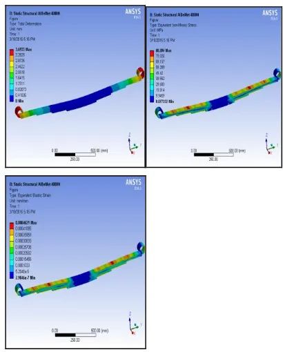
5.2.2 AlBeMet under 4000N load
Total deformation, equivalent stress, equivalent elastic strain of AlBeMet for load equal to 2000N is shown below in figure (5)
Fig -5: Total deformation, equivalent stress, equivalent elastic strain of AlBeMet for load equal to 4000N.
5.2.3 AlBeMet under 5000N load
[image:5.595.319.524.425.680.2]© 2016, IRJET | Impact Factor value: 4.45 | ISO 9001:2008 Certified Journal | Page 824
Fig -6: Total deformation, equivalent stress, equivalentelastic strain of AlBeMet for load equal to 5000N. 5.3.1 EGLASS/EPOXY under 2000N load
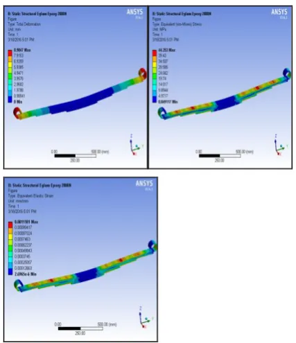
Total deformation, equivalent stress, equivalent elastic strain ofE-glass/Epoxy for load equal to 2000N is shown below in figure (7)
[image:6.595.49.265.91.334.2]
Fig -7: Total deformation, equivalent stress, equivalent elastic strain of E-glass/Epoxy for load equal to 2000N. 5.3.1 EGLASS/EPOXY under 4000N load
[image:6.595.48.262.420.668.2]Total deformation, equivalent stress, equivalent elastic strain of E-glass/Epoxy for load equal to 4000N is shown below in figure (8)
Fig -8: Total deformation, equivalent stress, equivalent elastic strain of E-glass/Epoxy for load equal to 4000N. 5.3.1 EGLASS/EPOXY under 5000N load
Total deformation, equivalent stress, equivalent elastic strain of E-glass/Epoxy for load equal to 5000N is shown below in figure (9)
Fig -9: Total deformation, equivalent stress, equivalent elastic strain of E-glass/Epoxy for load equal to 5000N.
[image:6.595.320.524.428.675.2]© 2016, IRJET | Impact Factor value: 4.45 | ISO 9001:2008 Certified Journal | Page 825
Table -6: Result comparison of steel (60SI7), AlBeMet and [image:7.595.50.271.286.367.2]E-Glass fiber epoxy under 2000N.
Table -7: Result comparison of steel (60SI7), AlBeMet and E-Glass fiber epoxy under 4000N.
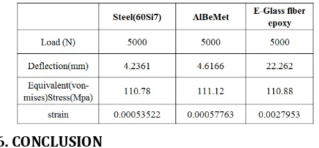
Table -8: Result comparison of steel (60SI7), AlBeMet and E-Glass fiber epoxy under 5000N.
6. CONCLUSION
The study verified that composites can be used for leaf springs for light weight vehicles and meet the necessities, together with significant weight savings. The 3-D modeling of both steel and composite leaf spring is done and analyzed. A relative study has been made between composite and steel leaf spring with respect to Deflection, strain energy and stresses. The 3-D modeling of composite leaf spring is done and analyzed using ANSYS. A relative study has been made between composite and steel leaf spring with respect to weight and strength. Under the same static load conditions the deflection and the stresses in the composite leaf springs and conventional steel leaf spring are found with huge variation. Deflection and Stresses in conventional steel leaf springs is found out to be more than composite leaf springs.
7. REFERENCES
[1] Rajendran, S. Vijayarangan “Optimal Design of a
Composite Leaf Spring Using the Genetic
Algorithms”Computer and Structures 79 (2001) 1121-1129
[2] J.J.Fuentes, H.J. Aguilar , J.A. Rodr´ıguez, E.J. Herrera ,
Premature fracture in automobile leaf springs Engineering Failure Analysis, P.P.648–655, 2009
[3] Bhushan B. Deshmukh1 ,Dr. Santosh B. Jaju Design and
Analysis of Fiber Reinforce Polymer (FRP) Leaf Spring - A Review Int. EnggTechsciVol 2(4) 2011,289-291
[4] B.R. Kumar, D. K. Bhattacharya, Swapan K. Das, S. G.
Chowdhury. 2000. Premature fatigue failure of a spring due to quench cracks. Engineering Failure Analysis, Vol 7, Issue 6, 377-384
[5] K. Tanabe, T. Seino, Y. Kajio, Characteristics of
Carbon/Glass Fiber Reinforced Plastic Leaf Spring, 1982.
[6] Al-Quershi HA. Automobile leaf springs from composite
[image:7.595.39.269.415.522.2]