© 2015, IRJET ISO 9001:2008 Certified Journal Page 199
Modeling and Simulation of BLDC Motor using MATLAB/SIMULINK
Environment
SudhanshuMitra
1, R.SaidaNayak
2, Ravi Prakash
31
Electrical Engineering Department, Manit Bhopal, India
2
Electrical Engineering Department, Manit Bhopal, India
3
Electrical Engineering Department, Manit Bhopal, India
---***---Abstract: Brushless DC Motors are specifically used forvariety of industrial applications like traction drive and electric vehicle application and heating ventilation system because of its higher efficiency, high torque and low volume. Positioning control is mostly needed in BLDC motor. Due to over-weighing merits of this motor modeling is done in order to enhance the performance of the system. This paper presents the applications, various control schemes used and modeling of BLDC Motor in MATLAB/SIMULINK environment.
I. Introduction
BLDC motor has simple structure and lower cost than other AC motors therefore it is used in variable-speed control of AC motor drives [1]-[2].They have better speed versus torque characteristics, higher efficiency and better dynamic response as compared to brushed motors and also it delivers higher torque to the motor which makes it useful where space and weight are critical factor. For torque production BLDC motor also need position information which is obtained by using hall sensors.
The machine is having three phase stator with three phase distributed winding and the torque of the BLDC motor depends on the respective position of the Back-emf. Usually the BLDCM has trapezoidal back-Emf waveform and stator is fed by rectangular stator current and theoretically it gives a constant torque but the torque ripple exists due to emf waveform imperfection, current ripple and phase current commutation.
The phase shift in emf waveform results from variation in shapes of the slots, skew and magnet of BLDC Motor and all the above said factors are subjected for the design consideration. This presents a BLDCM Model with the trapezoidal and sinusoidal back-EMF waveform. Fig.1 below shows general block diagram of BLDC motor control.
Fig.1 Block Diagram of BLDC Motor Control Scheme
For starting and for providing proper commutation sequence to turn on the power devices in the inverter bridge the BLDC motor requires a rotor position sensor. The power devices are commutated after every sequentially 60 degrees rotation of rotor. Instead of commutating the armature current using brushes, electronic commutation is used for this reason it is an electronic motor. This eliminates the problems associated with the brush and the commutator arrangement, for example, sparking and wearing out of the commutator brush arrangement, thereby, making BLDC more rugged as compared to a dc motor.
The basic block diagram of bldc motor control consist power converter, permanent magnet-synchronous machine (PMSM) sensors, and control algorithm. Three phase inverter transforms power from the source to the PMSM which in turn converts electrical energy to mechanical energy. BLDC motor has rotor position sensors controlled by the command signals , the command signal may be classified as
© 2015, IRJET ISO 9001:2008 Certified Journal Page 200 voltage source and current source based drives.
Permanent magnet synchronous machine with either sinusoidal or non-sinusoidal back-Emf waveforms is used by both voltage source and current source based drive.
The inverter size and losses for the same power size is reduced by the Machine with a non-sinusoidal back-Emf. Whereas in order to achieve constant torque, Machine with a sinusoidal back-Emf can be controlled.
The BLDC motor can be classified into two types according to the back-Emf signal such as sinusoidal back-Emf type or Trapezoidal back-Emf type.
Few applications of BLDC Motors can be described as follows :-
[1] Electric Vehicle – High power BLDC motor is used in electrical vehicle application due to high efficiency of motor. Basically it is used in “electric bicycles”. The stator of the motor is attached with the axle of the bicycle and the rotor is attached with the wheel.
[2] Heating and Ventilation System – BLDC motor is used in HVAC system for driving various fans like in operation of Damper and actuator. Initially conventional AC Motors are used in HVAC system but these motors are large power consuming machine. Therefore BLDC Motors are rapidly replacing conventional AC Motors. BLDC Motor is electronically controlled motor and the feature makes it useful for variable speed and variable load operations.
[3] Industrial Engineering Applications – Due to high efficiency, good speed torque characteristics, wide speed range operations and low maintenance requirements the BLDC motors are widely used in manufacturing industries. They are basically used in linear motor and servo applications.
[4] Motion Control System – BLDC motors are used in adjustable as well as variable speed operations like in pumps and fan drive. They are most useful in servo applications. Initially stepper motor is widely used in servo applications but because they are operated in open loop control application therefore produces torque pulsation in the output and servo applications are based in precise motion operation and is the main reason for using BLDC motor because it is operating in closed loop operations.
[5] Positioning and Actuator System – BLDC motor is used in various applications like assembling tasks especially in robotics, In assembly of robots it is used in various tasks like welding and painting. BLDC motor is used in actuator because it can efficiently use for linear motor applications. The application as a linear system is effectively used here without using the transmission system.
II. Control Schemes for BLDC Motor
In this paper, variable dc link voltage control scheme for speed control has been proposed. The hysteresis current control and carrier based control scheme are used for controlling the gate pulse of the inverter.
BLDC Motor can also be controlled by controlling the dc bus voltage or by PWM method. Some designs utilize both to provide high torque at high load and high efficiency at low load. Such hybrid designs also allows the control of harmonic current.
© 2015, IRJET ISO 9001:2008 Certified Journal Page 201
III. Mathematical Modeling.
BLDC motor which is modeled in this paper is a 3 phase 4 pole motor. A synchronous machine with Permanent magnet rotor can also be considered as BLDC motor and the only difference is the rotor construction due to which the dynamic characteristics of the machine changes and the three phase voltage source is fed to the motor. A sinusoidal square wave is not necessarily used as source or the other wave shape can also be used but it should not exceed the maximum voltage limits. The modeled equations for the armature winding are as follows:-
𝑉𝑎 = 𝑅𝑖𝑎 + 𝐿𝑑𝑖𝑎/𝑑𝑡 (1) 𝑉𝑏 = 𝑅𝑖𝑏 + 𝐿𝑑𝑖𝑏/𝑑𝑡 (2) 𝑉𝑐 = 𝑅𝑖𝑐 + 𝐿𝑑𝑖𝑐/𝑑𝑡 (3) Where
L-armature selfinduction in [H] R-armature resistance in [Ω]
Va, Vb, Vc –terminal phase voltage in [V] ia, ib, ic-motor input current in [A] ea, eb, ec-motor back-Emf in [V]
Back-Emf of each phase has a phase difference of 120 electrical degrees and back- Emf and rotor position are related via some function. Equation of each phase for back-Emf is as follows:-
𝑒a=(𝜃𝑒)𝜔 (4) 𝑒b=(𝜃𝑒 − 2𝜋/3) (5) 𝑒c=(𝜃𝑒+2𝜋/3) (6)
Where
Kw - back-Emf constant of one phase [V/rads-1] θe- rotor angle in electrical degree
ω- rotor speed[rad.S-1]
Rotor angel electrical [𝜃e] and Rotor angle mechanical [𝜃m] are related as:-
𝜃𝑒 = 𝑃/2𝜃𝑚 (7)
Where P is the no of poles on rotor
Thus the total electromagnetic torque Te in N-M can be expressed as follows:-
𝑇e = (𝑒𝑎𝑖𝑎+𝑒𝑏𝑖𝑏+𝑒𝑐𝑖𝑐)/ 𝜔 (8)
The mechanical torque transferred to the motor shaft:-
𝑇𝑒 − 𝑇𝑙= 𝐽𝑑𝑤/𝑑𝑡+ 𝐵𝜔 (9)
Where
Tl = load torque [N-M]
J= inertia of the rotor shaft [Kgm2] B = friction constant [Nms.rads-1]
IV.
Simulink Model
It is important to give precise value of torque to the model in order to design BLDC Motor drive system becauseit is related to back-Emf and torque [4].For energizing the stator winding in correct sequence the knowledge of rotor position is necessary since in order to rotate the rotor stator winding has to be energized sequentially and also commutation has to be done electronically.
The speed control has been done on variable dc link voltage control technique and finally theresults are verified.
© 2015, IRJET ISO 9001:2008 Certified Journal Page 202 V.
Simulation Result
Table I. BLDC Motor Specification
PARAMETERS VALUE UNIT
Vd 485.9 V
Stator Phase Resistance RS
2.875 Ω
Armature Inductace H
8.5*10-3 H
No. of Poles 4
Inertia 0.8*10-3 Kgm2
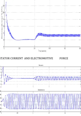
With the above design consideration the simulation has been done and the result is presented here. Speed is set at 3000 rpm and load torque disturbance is applied at 0.01 sec and the speed regulation is obtained at the set speed. The back Emf and stator waveform are shown by the simulation waveform and it shows that back-Emf and phase voltage both are displaced by 120 degree each and stator current are of quasi sinusoidal in nature and also displaced by 120 degree.
ROTOR SPEED VS TIME
TORQUE VS TIME
STATOR CURRENT AND ELECTROMOTIVE FORCE
© 2015, IRJET ISO 9001:2008 Certified Journal Page 203 LINE TO LINE VOLTAGE
VI. Conclusions
The modelling of BLDC Motor using PI controller is presented in this paper. The feed back signal and commutation mechanism utilises speed, position of the rotor and stator current. All the simulation results are of theoretical aspects and can be utilized for practical implementation.
REFRENCES
[1]T. Raghu, S. Chandra Sekhar, J. SrinivasRao, ―SEPIC Converter based-Drive for Unipolar BLDC Motor‖, International Journal of Electrical and Computer Engineering (IJECE), Vol.2, No.2, April 2012, pp. 159-165
[2] A. HalvaeiNiasar, AbolfazlVahedi, Hassan Moghbeli, ―Torque Control of Brushless DC Motor Drive based on DSP Technology‖, Proceeding of International Conference on Electrical Machines and Systems 2007, Oct. 8~11, Seoul, Korea.
[3] F. Rodriguez and A. Emadi, ―A novel digital control technique for brushless DC motor drives,‖ IEEE Transaction Industrial Electronics., vol. 54, no. 5, pp. 2365–2373, Oct. 2007
[4] C. Gencer and M. Gedikpinar, ”Modelling and Simulation of BLDC Motor Using MATLAB/SIMULINK”, Journal of Applied Sciences, vol. 6, issue 3, pp. 688-691, 2006
[5] Vinod Kr Singh Patel, A.K. Pandey, “Modelling and Simulation of Brush less DC Motor Using PWM Control Technique”, IJERA Transaction, vol. 3, issue 3, May – jun 2013
[6] G. Prasad, N. Sree Ramya,” Modelling and Simulation Analysis of the Brush less DC Motor by using MATLAB”,IJITEE Transaction, vol. 1, issue 5 October 2012