Comparative Study on Different Dual-Band
HIS Structures
H. Wadie Badri1, H. Zairi2, A. Gharsallah3
PhD Student, Dept. of Physics, Faculty of Sciences of Tunis, Tunis, Tunisia1
Assistant Professor, Dept of EE, ESTI, Tunis, Tunisia2
Full Professor, Dept. of Physics, Faculty of Sciences of Tunis, Tunis, Tunisia3
ABSTRACT In this paper, we present a comparative study of two different dual-band high impedance surfaces (HIS) to be used as ground planes. These structures are designed to behave as a magnetic conductor surface for global positioning system (GPS) standard frequencies L1 (1575 MHz) and L2 (1227 MHz). Each of the two surfaces is characterized by performing parametric studies of its unit cell. The studies were carried out using CST Microwave Studio Simulation software. The results show that the two-layer cell gives the best bandwidth for high and low frequency bands.
KEYWORDS: EBG, Dual-band-HIS, Reflection phase.
I. INTRODUCTION
Microstrip antennas are widely used in a variety of areas, such as wireless communication systems, RFID, satellite communications and GPS systems [1-2]. But these antennas usually have bidirectional radiation pattern and low gain [2]. In order to achieve directional radiation characteristics, they need to be integrated with a reflector. However, for dual-band antennas it is difficult to realize well matched directional characteristics over both working frequencies when using a conventional metallic reflector.
In this context, HIS have been introduced like reflectors to improve antennas profile. The combination of a dual-band high-impedance surface reflector and the antenna provides directional properties for both frequency bands [3]. The high-impedance surface (HIS) is a king of electromagnetic band gap (EBG) material that has the property of magnetic conductor surface within its band gap frequencies [4]. Over the past decade, high-impedance surfaces are widely used in microwave and antenna engineering for their ability to realize relatively low-profile, high-gain and high-efficiency antenna in close proximity to metallic surfaces [5]. Various kinds of HIS structures have been proposed and investigated [6-7-8]. This study focuses on dual-band HIS structures.
In this paper, we present a comparative study of two different dual-band HIS structures that can be used as HIS reflector for dual-band antenna which is working at L1 and L2 GPS frequencies of 1.227 GHz and 1.575 GHz. The first structure is composed of one layer while the second is composed of two layers.
Therefore, the present paper is divided into four main parts. First of all, section I presents the introduction. Besides, section II highlights the design and the parametric studies of the dual-band HIS structures. Then, section III focuses on acomparative study of the structures and finally section IV presents the conclusion and recommendations for further studies.
II. DUAL-BAND HIS STRUCTURES
simulations were carried out using CST microwave studio with the imposition of a periodic boundary condition (PBC) [9]. The simulation setup is the same as used in [10].
A. The first HIS cell
Fig.1 The geometry of the first dual-band HIS cell. (a) top view, (b) side view.
As shown in fig. 1, the first dual-band HIS cell design consists of a concentric square patch with square ring slot. In [11-12], this cell has been designed for WiFi standards 2.4 GHz and 5.5 GHz. In this study, the dimensions of the HIS were optimized to achieve the 0° phase around 1.227 GHz and 1.575 GHz. The studied HIS cell is printed on one layer of Roger substrate with thickness of 6 mm, relative permittivity of 1.96 and loss tangent of 0.0019.
W
cellis the cellwidth,
W
bis the width of the inner patch, Wh is the width of the outer patch andg
is thegap width.0.4 0.6 0.8 1.0 1.2 1.4 1.6 1.8 2.0 2.2 2.4 2.6 -210
-180 -150 -120 -90 -60 -30 0 30 60 90 120 150 180 210
R
fl
e
c
ti
o
n
P
h
a
s
e
(d
e
g
re
e
)
Frequency (GHz)
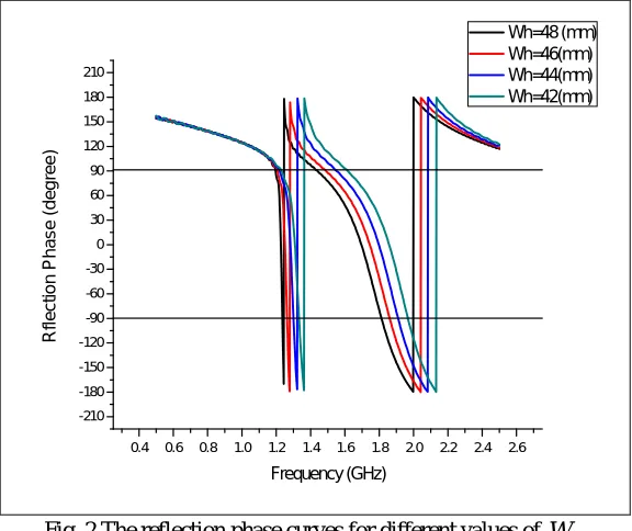
Wh=48 (mm) Wh=46(mm) Wh=44(mm) Wh=42(mm)
Fig. 2 The reflection phase curves for different values of Wh
The results of the reflection phase for different values ofWhare presented in fig. 2. From these results we can see that
when decreasing the width of the outer patch Whfrom 48 mm to 42 mm, the frequency in which the reflection phase is
h
b
W
g
Ground Patch
Substrate
cell
W
h
W
(a)
0° (resonant frequency) at the high frequency band is increasing, from 1.63 GHz at 48 mm to 1.9 GHz at 42 mm. While it increases slightly in the low frequency band.
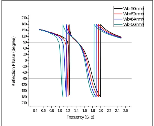
Fig. 3 shows the reflection phase for different width of the inner patch
W
b. As can be seen from the figure, whenW
bchange from 50 mm to 56 mm, the resonant frequency (when the reflection phase is 0°) decreases in the low band from 1.226 GHz to 1.08 GHz. While the resonant frequency in the high band decreases from 1.68 GHz when
W
b is 50 mmto 1.62 GHz when
W
b is 56 mm.0.4 0.6 0.8 1.0 1.2 1.4 1.6 1.8 2.0 2.2 2.4 2.6 -210
-180 -150 -120 -90 -60 -30 0 30 60 90 120 150 180 210
R
e
fl
e
ct
io
n
Ph
a
se
(d
e
g
re
e
)
Frequency (GHz)
Wb=50(mm) Wb=52(mm) Wb=54(mm) Wb=56(mm)
Fig. 3 The reflection phase curves for different values of
W
bB. The second HIS cell
Fig. 4 The geometry of the second dual-band HIS cell. (a) top view, (b) side view.
The geometry of the second cell is shown in fig. 4. This cell consists of two stacked square patches; the smallest is on top of the larger. The studied cell is printed on two layers of Roger substrate with thickness of 3 mm each one, relative permittivity of 1.96 and loss tangent of 0.0019.The followingare the dimensions of the HIS cell:
L
cellis the cell width,b
L
is the large patch width and Lh is the width of the small patch in top.Bottom patch
Top patch
(a)
(b)
bL
L
hcell
L
0.4 0.6 0.8 1.0 1.2 1.4 1.6 1.8 2.0 2.2 -210
-180 -150 -120 -90 -60 -30 0 30 60 90 120 150 180 210
R
e
fl
e
c
ti
o
n
P
h
a
s
e
(
d
e
g
re
e
)
Frequency (GHz)
Lb=64(mm) Lb=67(mm) Lb=70(mm) Lb=73(mm)
Fig. 5 The reflection phase curves for different values of
L
bAs shown in fig. 5, the reflection phase curves decreases, significantly, in the low frequency band when the values of the width of the large patch
L
b increase from 64 mm to 73 mm. In the high frequency band the reflection phase remains the same with a slight change.0.4 0.6 0.8 1.0 1.2 1.4 1.6 1.8 2.0 2.2 -210
-180 -150 -120 -90 -60 -30 0 30 60 90 120 150 180 210
R
e
fl
e
c
ti
o
n
P
h
a
s
e
(
d
e
g
re
e
)
Frequency (GHz)
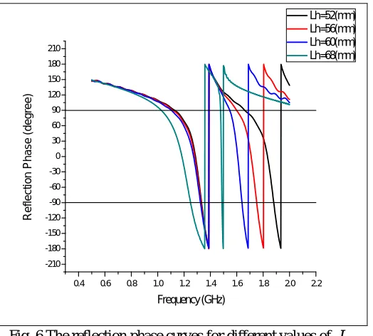
Lh=52(mm) Lh=56(mm) Lh=60(mm) Lh=68(mm)
Fig. 6 The reflection phase curves for different values of Lh
By observing the reflection phase for different values of Lh which are shown in fig. 6, it can be concluded that the
values ofLh affect the high frequency band. The resonant frequency decreases from 1.83 GHz to 1.49 GHz when Lh
III. COMPARATIVE ANALYSIS
TAB.1 Design specifications of the two HIS cells
Parameters (mm)
First cell
W
cell
58
W
b
50
Wh 4 8 .30.7
g
h
6
Second cell
L
cell
74
L
b
69
Lh 6 1 .56
h
Tab. 1 highlights the design specifications of the structures. It is noticeable that the first dual-band HIS with one layer is the smallest with cell size of 58 mm while the two-layer cell size is 69 mm.
0.4 0.6 0.8 1.0 1.2 1.4 1.6 1.8 2.0 2.2 -210
-180 -150 -120 -90 -60 -30 0 30 60 90 120 150 180 210
R
e
fl
e
c
ti
o
n
P
h
a
s
e
(
d
e
g
re
e
)
Frequency (GHz)
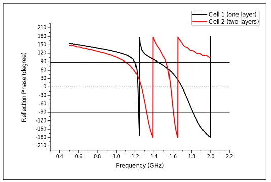
Cell 1 (one layer) Cell 2 (two layers)
Fig. 7 The reflection phase curves for the two dual-bands HIS cells
Fig. 7 shows the reflection phase of the two cells. The simulation parameters are presented in table 1. As seen in fig. 7 and table 3, the first cell with one layer resonated at two frequencies of 1.22 GHz and 1.68 GHz. The bandwidth between the +/- 90 degree points in the reflection phase curve of the low resonant frequency is 2% (25 MHz) and at the second resonant frequency is about 20% (350 MHz). It isobvious that the bandwidth at the low frequency (1.22 GHz) is very narrow. The reflection phase of the two-layer cell (the second cell) ,which is presented in the same figure, is resonated at 1.226 GHz and 1576 GHz with a bandwidth of 17% and 3.5% ,respectively, as presented in table 2 for low and high frequencies band.
TAB. 2 Resonant frequencies and bandwidth of the two cells
Low band High band
Bandwidth (%) Bandwidth (MHz) /
0
f
(GHz)Bandwidth (%)
Bandwidth (MHz) /
0
f
(GHz)First cell 2 25 / 1.220 20 350 / 1.68
Based on the results analysis above, it can be concluded that the two-layer cell gives the best results. Even that its bandwidth at the high frequency band is less than that given by the first cell. Another signification point to notice is that, the resonant frequency at the high frequency band for the first cell is not at the desired frequency of GPS standard L2 (1575 MHz). However, for the two-layer cell the low and high resonant frequencies are at L1 and L2 of GPS standard.
IV. CONCLUSION
In this work, we have comparatively investigated the performances of two different dual-band HIS structures. The geometry of the designed structures was introduced and a parametric study was conducted for each one. The reflection phase of the two structures was compared. The analysis results allow us to see that the two-layer cell give the best performances. For further study, it will be necessary to determine the characteristics (return losses and radiation diagram) of a dual-band antenna with the presence of each structure.
REFERENCES
1. X. L. Bao, G. Ruvio, and M. J. Ammann, "Directional dual-band slot antenna with dual-bandgap high-impedance-surface reflector," Progress In Electromagnetics Research C, Vol. 9, pp.1-11, 2009.
2. X. Mu, W. Jiang, S.-X. Gong, and F.-W. Wang, "Dual-band low profile directional antenna with high impedance surface reflector," Progress In Electromagnetics Research Letters, Vol. 25, pp.67-75, 2011.
3. Thior, A. Lepage, and X. Begaud, "Low profile, directive and ultra wideband antenna on a high impedance surface," IEEE 3rd European Conference on Antennas and Propagation, 2009.
4. D. Sievenpiper, L. Zhang, R. Broas, N. Alexopolous, and E. Yablonovitch , “High-impedance electromagnetic surfaces with a forbidden frequency band,” IEEE Trans. Microw. Theory Tech., vol. 47, no. 11, pp. 2059–2074, Nov. 1999.
5. H.-J. Lee, K. L. Ford, and R. J. Langley, “Independently tunable low-profile dual-band high-impedance surface antenna system for applications in UHF band,” IEEE Transactions on Antennas and Propagation, vol. 60, no. 9, pp. 4092–4101, 2012
6. C.H. Huang, C.K. Chen, L.H. Lee and M.S. Lin “T-slot high-impedance surface structures for EMC of wireless products” 9th International Conference on Information, Communication and signal Processing (ICICS) 2013.
7. T. Yuan, H. Hafdallah-Ouslimani, A. C. Priou, G. Lacotte, and G. Collignon, "Dual-layer EBG structures for low-profile ``bent'' monopole antennas," Progress In Electromagnetics Research B, Vol. 47, pp.315-337, 2013.
8. X. Chen, L. Li, C.-H. Liang, Z.-J. Su, C. Zhu, “Dual-band high impedance surface with mushroom-type cells loaded by symmetric meandered slots” IEEE transactions on antennas and propagation, VOL. 60, NO. 10, OCTOBER 2012
9. N. Capet, C. Martel, J. Sokoloff, and O. Pascal, "Optimum high impedance surface configuration for mutual coupling reduction in small antenna arrays," Progress In Electromagnetics Research B, Vol. 32, pp.283-297, 2011.
10. F. Yang and Y. Rahmat-Samii, “Reflection phase characterizations of the EBG ground plane for low profile wire antenna applications,” IEEE Transactions on Antennas Propagation, vol. 51, no. 10, pp. 2691–2703, Oct. 2003.
11. S. Zhu and R. Langley, “Dual-band wearable textile antennas over EGB substrate”. IEEE Transactions on Antennas Propagation, Vol 57, pp.926-935, 2009.