Vol. 4, Issue 2, February 2015
Zeta Converter Fed Integrated Inverter For
Grid Connected PV System with Optimal
Power Point Tracking
Neeraj Priyadarshi
1, Dr.Vinod kumar
2, Dr.R.R Joshi
3PhD scholar, Department of Electrical Engineering, College of Technology & Engineering, Udaipur (Rajasthan), India1
Assistant Professor, Department of Electrical Engineering, College of Technology & Engineering, Udaipur, India2
Professor, Department of Electrical Engineering, College of Technology & Engineering, Udaipur (Rajasthan), India3
ABSTRACT: For high power efficiency in the grid connected PV system zeta converter fed integrated inverter grid connected PV system has been proposed.A perturb and observe MPPT for zeta converter has been proposed for optimal power point tracking. The proposed system integrates optimum power point tracking, dc side buck boost voltage and inverter current injected into the grid. The integrated inverter is controlled by hysteresis current controller. The simulation results have been verified using MATLAB/SIMULINK environment.
KEYWORDS:Grid connected PV system, MPPT, Zeta converter, MATLAB/SIMULINK
I. INTRODUCTION
The fossil fuel and nuclear fission are the energy sources which are needed to produce electric power. The burning of fossil fuel produces the harmful gases and toxic metals to the environment. Renewable energies are playing a vital role in supplying the world’s required power demands. The photovoltaic power generation system keeps growing in the last few decades to produce promising source of energy. The present PV systems are not very efficient and having 12-20% efficiency to convert solar power to electrical power [1-3]. The drop in efficiency of solar array is due to the variable irradiance and ambient temperature. In order to extract the optimal power from solar array it is important to operate the solar array at its optimal power point. Hence Maximum Power Point Tracking algorithms are required to extract optimum power from the PV Array at variable irradiance level and environmental temperature[4-6]. In this paper a perturb and observe based MPPT has been proposed due to fast and easy computational analysis. The proposed Zeta converter gives low voltage ripple compared to other conventional dc-dc converter. The integrated inverter has been controlled by hysteresis current control which gives fast dynamic response, high efficiency and low THD compared to other conventional current control.
II. RELATEDWORK
The structure of the proposed system is shown below in Fig.1.The block diagram shows the proposed zeta buck boost converter is controlled by P&O MPPT control,on the other hand the Three phase inverter has been controlled by hysteresis current controller.
Fig.2 Equivalent circuit of a PV cell
For obtaining the V-I characteristics of a PV cell, the equation is expressed as:
R IR V 1 IR V T AK q exp I -I P S S C 0 P h I …….(1) Where,Iph is the photocurrent, I0 is the reverse saturation current of the diode, q is the electronic charge, V is the output
voltage across the cell, K is the Boltzmann's constant, Tcis the operating cell temperature, A is the ideality factor of the
diode, and Rs and RPare the series and shunt resistors of the cell, respectively.
B.Zeta buck boost converter
The proposed zeta converter has been used as a MPPT tracker due to least output voltage ripple. It includes two capacitors and two inductors as dynamic storage elements and able to amplify and reduce the input voltage levels without inverting the polarities. Zeta converter works in two modes of operation. In first mode of operation, when switch is closed, the current flows through inductor Land L1 while diode is reversed biased. In second mode of
operation when switch is opened, the diode is conducting and all the energy stored in inductor L1 is transferred to Load
RL as shown in Fig3.
Fig.3 Circuit of zeta converter
C.Purturb and observe (P&O) MPPT
Vol. 4, Issue 2, February 2015
Fig 4 P&O method using Matlab/simulink
D.Integrated inverter control
The integrated inverter is controlled by shunt active filter scheme.
1. Generation of reference current for each phase of inverter
The proposed system used instantaneous reactive power (IRP) theory for the Generation of reference current for each phase of inverter. The Instantaneous Reactive Power theory s describes the Clarke transformation of the three phase input voltages and the three phase load currents in the a-b-c coordinates to the α-β-0 reference frame followed by the calculation of the real and reactive instantaneous power components. From figure it is clear that the input voltage and load current are transformed, and processed to generate reference current commands as a input to a hysteresis current controller to generate the gating signal for inverter, shown in Fig.5.
Fig.5 MATLAB/SIMULINK implementation of the generation of the reference current
2. Generation of gating pulses for inverter
The proposed system used nonlinear control based hysteresis current controller for generation of gating pulses to the inverter. It generates the switching pattern for current controlled voltage source inverters which gives precise and quick response, as shown in Fig6.
Fig.7 Simulink model zeta fed of Integrated Inverter with P&O MPPT
The simulation is implemented in MATLAB/SIMULINK environment with P&O algorithm as shown in Fig7. Under the same irradiation and temperature conditions, the PV array continued to generate around 200 Watts. In this case the power obtained by the PV array at the load side is found to be around 200 Watts. Under different weather conditions fuzzy logic based MPPT shows better performance in MPPT applications. The above simulation results show tracking capability of the proposed system at different insolations.
Case I: When the ambient temperature and solar irradiance kept constant T=250C,S=1000 W/m2.
(a) (b)
Fig (a) shows the constant irradiance level and (b) shows the solar power at constant irradiance and constant temperature i.e at T=250C,S=1000 W/m2.
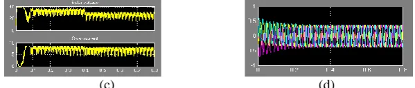
(b) (d)
Fig(b) and (c) show the solar voltage,solar current and inverter current at standard irradiance and ambient temperature respectively. The MATLAB/SIMULINK results of Integrated Inverter for grid connected PV system with MPPT are shown in Figure. It can be conclude from the above figure that the system reaches the maximum power point at time t=0.15 sec. Time t=0 to t=0.02sec is a period for the system to initialize its state. At time t=0.02 sec, the PV cell has output voltage, on the other hand solar power and solar current is zero. From period t=0.02sec to t=0.15sec, the simulated MPPT based P&O method waveform has overshoot. After t=0.15sec, the waveform are constant throughout.
(e) (f)
Vol. 4, Issue 2, February 2015
(g)
Fig.8 (a) Constant solar irradiance (b) Solar power(c) Solar voltage and current(d)Inverter current(e) Inverter voltage(f) Grid voltage (g) Grid current
Case II:When the ambient temperature kept constant (250C), and the solar irradiance varies from 1000 W/m2 to 400 W/m2 at time t=0.3s.
(a) (b)
The above simulation results are shown, when cell temperature remains constant and solar irradiance level changes. It is clear from the figure that at time t=0.3s the output solar power decreases due to sudden reduction in irradiance level at 0.3 sec .On the other hand the solar output voltage increases and the solar output current increases.
(c) (d)
After t=0.5ecs the waveforms of solar power, solar voltage and solar current shakes up and down regularly. From above simulation results 9 (b) &(c), it is clear that the proposed system always run at maximum power, no matter what the operating condition is.
(e) (f)
The simulation results show that due to variation in irradiance level also the proposed system has purely sinusoidal waveform of inverter current, as shown in fig9(d).the sinusoidal grid voltage and grid current are also shown in fig9 (f) & (g).
(g)
(a) (b)
The simulation results are shown, when solar insolation kept constant and cell temperature changes. It is clear from the figure that at time t=0.4sec, the output solar power, solar voltage and solar current increase due to sudden change in environment temperature.
(c) (d)
After time t=0.4sec, the solar power, solar voltage and solar current waveforms shake up and down regularly. This P&O based MPPT can work effectively when environmental temperature changes suddenly. The above simulation results show tracking capability of the proposed system at different insolations.
(e) (f)
Simulation results show that fig10 (b) &(c), due to variation in ambient temperature also the proposed system works at maximum power. From figure 10 (d), (f) & (g), it is clear that inverter current, grid voltage and grid currents are sinusoidal in nature. The inverter current is in phase with the grid voltage.
(g)
Fig.10 (a) variable solar irradiance (b) Solar power(c) Solar voltage and current(d)Inverter current(e) Inverter voltage(f) Grid voltage (g) Grid current
IV.CONCLUSION
Vol. 4, Issue 2, February 2015
REFERENCES
1. J. L. Santos, F. Antunes, A. Chehab, and C. Cruz, "A maximum power point tracker for PV systems using a high performance boost converter," Solar Energy, vol. 80, pp. 772-778, 2006.
2. G. Walker, "Evaluating MPPT converter topologies using a MATLAB PV model," Journal of Electrical & Electronics Engineering, vol. 21, pp. 49-56, 2001.
3. A.Yazdani and R.Iravani, “An accurate model for the dc-side voltage control of the neutral point diode clamped converter,” IEEE Trans.Power Del., vol. 21, no. 1, pp. 185–193, Jan. 2006.
4. S.K. Chung, “A phase tracking system for three phase utility interface inverters,” IEEE Trans. Power Electron., vol. 15, no. 3, pp. 431–438, May 2000.
5. O.Wasynczuk, N. A. Anwah, “Modeling and dynamic performance of a self-commutated photovoltaic inverter system,” IEEE Transaction on Energy Conversion, vol.4, no.3, pp. 322-328, Sep. 1989.