ISSN (Online) : 2319 - 8753 ISSN (Print) : 2347 - 6710
I
nternationalJ
ournal ofI
nnovativeR
esearch inS
cience,E
ngineering andT
echnology Volume 3, Special Issue 3, March 20142014 International Conference on Innovations in Engineering and Technology (ICIET’14)
On 21st & 22nd March Organized by
K.L.N. College of Engineering, Madurai, Tamil Nadu, India
ABSTRACT— Controlling of level process is one of the most common problems in the process industry. In this paper, system identification is attempted for hybrid tank process which is a classic example of a highly nonlinear system. System identification provides a better alternative to find their system transfer function which yields accurate model for nonlinear systems. The inflow rate of the hybrid tank is measured using a turbine flow meter and the output level is measured using a differential pressure transmitter (DPT). The system identification process is used here to identify the transfer function, nature of the system using the inputs and the outputs available. From the obtained transfer function the controllers such as PID, IMC and Fuzzy logic controller is implemented and their performance analysis is carried out.
KEYWORDS— Process control, nonlinear dynamics, nonlinear process control, System identification process, Proportional Integral Derivative (PID) controller, Internal Model Controller(IMC), Fuzzy logic controller.
I. INTRODUCTION
The basic control problem is to regulate the liquid level in the tank by varying the speed of the circulating pump. The apparatus consist of two separate glass tanks are inter connected by a flow channel, both with drain valves to common reservoir situated below. A variable area valve in this Channel is used to vary the flow characteristics between the tanks. A speed of the pump is set to fill the left tank either in manual or automatic control performance was monitored. Alternatively the second tank can be filled from the first tank, via varying different positions of the valve, and again performance
tank is clearly visible through the transparent glass. System identification involves building mathematical models of a dynamic system based on a set of measured stimulus and response of sample data. Here we focus on the design of the hybrid tank process transfer function model. Simulation is an inexpensive and fast way to practice many problems unimaginable in laboratory experiments. Simulation does not replace laboratory experiments
II. HYBRID TANK PROCESS
The continuous-flow, well-stirred tank reactor finds wide application in the chemical industry from pilot plant to full-scale production operation. The basic arrangement, sketched below, comprises a tank thermostated at some surrounding temperature Ta into which one or more reactant feed streams flow at some controlled rate. The contents react in the tank and are stirred either mechanically or as a consequence of the flow characteristics, and there is an outflow. The continuous inflow of fresh reactants provides a thermodynamically open system, in which true steady state behavior can be sustained 'indefinitely'.
System Identification And Design Of
Controllers For A Hybrid Tank System
A.Harivignesh
1, Mr.P.Tamilmani
2, Ms.P.Kalaiyarasi
3M.E .Control and Instrumentation, Department of EIE, Valliammai Engineering College, SRM Nagar, Kattankulathur, Kancheepuram, India. 1
M.E .Control and Instrumentation, Department of EIE, Valliammai Engineering College, SRM Nagar, Kattankulathur, Kancheepuram, India. 2
Copyright to IJIRSET www.ijirset.com 565 Fig.1 Hybrid tank system.
A. Level process
The level of the hybrid tank is measured using level transmitter. Level transmitter used here is DPT (Differential Pressure Transmitter). Finding the difference in pressure between the atmosphere and tank to obtained the differential pressure. DP instruments are usually mounted in a flange or threaded port near the bottom of the vessel. These instruments require periodic calibration. Output signal from DPT is (4 to 20) mA which is given as input to I/P converter. I/P converter converts the current (4 to 20) mA into (3 to 15) psi pressure signal. The output of I/P converter is displayed in G3 (Gauge).The output of I/P is given as input to the pneumatic valve.
Fig.2 Hybrid tank process.
Thereby, the pneumatic control valve controls the flow of water from reservoir tank to the process tank. Inflow to the process tank is measured using rotameter.
B. System Identification
System identification is the art and science of building mathematical model of dynamic systems from observed input-output data.
Steps in System Identification
The block diagram showing various steps involved in system identification is shown in fig.3.The system identification problem can be divided into a number of sub problems:
Experimental design Data collection
Model structure selection Model validation
Experimental Planning & Data Collection
It is the basis for the identification procedure, where process experiments are designed and conducted. The purpose is to maximize the information content in the data, within the limits imposed by the process.
ModelStructure Selection
The process models describe a system transfer function in terms of zeros, poles, integration and delay terms. In process models, number of non-zero poles is represented by Pn, where P stands for pole and n
represents the number of non-zero poles. Pn is followed
by Z for zero, I for integration, D for delay and U representing under-damped behaviour. A P1D structure models the system as a first order system with delay as shown in (1)
Where the steady-state-gain of the process is K, Td is
the time delay and Tp1 is the process time constant.
Equation (2) represents a P2D model that has two real poles placed at s = -1/Tp1 and s = -1/Tp2. Equation (3)
represents a P2DU model which is essentially a second order system with either a pair of complex poles or two poles depending upon the damping.
Where Tp1 and Tp2 are the time constants corresponding
to real poles, Tw is the time constant of the second
order system shown in (3) and is the damping factor. The parameters of the best model in terms of fit.
(1) ) sT (1
Ke G(s)
p1 s Td
) 2 ( ) 1 )( 1
( ) (
2
1 p
p s T
sT sT
Ke s
G
d
) 3 ( 2
1 ) (
2 2
s T s T Ke s
G
w w
s
Td
Fig.3 Block Diagram for System Identification
III. PROCESS MODEL SELECTION
The order of the model is selected by using MATLAB system identification tool box using 300 sample data. The prediction error method (PEM) is used to identify the model. The hybrid tank process has two tanks and the minimum order of the system is two. The parameters of the process models have obvious physical significance such as gain of the process and time constants.
Considering the fact that the coupled tank process has two interacting tanks the P2DU model is selected. The identified P2DU model transfer function is selected and the transfer function of the hybrid tank system considered is
Model validation
In the procedure the estimated P2DU model is applied to a different from the one used for estimation. In P2DU model, a fit% of 94.29 is obtained. Model validation can also be done by applying residual analysis on the experimental data.
IV.CONTROLLER DESIGN
A. PID Controller
The PID control algorithm remains the most popular Approach for industrial process control despite continual advances in control theory. This is not only due to the simple structure which is conceptually easy to
understand and, which makes manual tuning possible.The PID tuning rule used here is Zeigler-Nicholas tuning rule because it provides simple tuning formula to determine the P, PI and PID controller parameters [3]. According to Z-N tuning criteria the obtained Ku and Pu are 65.55 and 316.99 respectively. For PID controller, the values of tuning parameters obtained are Kp=50.741, Ti=0.6585, Td=185.5587.
B. Internal Model Controller
Internal model controller provides a transparent framework for control system design and tuning. The main feature of internal model controller is that the process model is in parallel with the actual process. The process model Gp(s) is factored in to two
parts, that is invertible part Gp-(s) and non-invertible
part Gp+(s), The non-invertible part consists of RHP
zeros and time delays. This factorization is performed so as to make the resulting internal model controller stable. Several methods of tuning of internal model controller and efficient calculation of filter parameter have been proposed in [2].
Fig.4. Internal model controller
( )
( )
p p p
G
G
s G
s
1
( )
p( ) ( )
Q s
G
s f s
2
2
2545.3034
112.0415808
1
1
( )
0.037031
(
1)
s
s
Q s
s
In practice λ is taken higher than the time constant value. So, the values of λ is obtained as 50 in the above equation we get the transfer function of internal model controller denoted by Q(s).
2
2
2545.3034
112.0415808
1
( )
92.5775
3.7031
0.03701
s
s
Q s
s
s
A. Fuzzy Logic Controller
The design of fuzzy logic controller consists of several steps. First, the variables for the fuzzy control
Qc
d
Gp
Gp*
Y
Y*
r
R
S1
d*
Validate
Calculated Model Choose Criterion to Fit Data
Choose Model Set Experimental
Design
If not ok, then repeat
If ok Use it. I/O Data
2
3034
.
2545
0415808
.
112
1
037031
.
0
)
(
s
s
S
G
p
Copyright to IJIRSET www.ijirset.com 567 system are determined. The universe are then set. Here, the
fuzzy controller is designed with two input variables and one output variable. The input variables are error and change in error that is difference between the set point level and actual level and the rate of change of error (de) and the output is controller output (co).
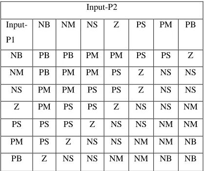
Fig.5. Fuzzy logic controller The above figure shows the fuzzy logic controller to control the level in the outlet of the system. Both the input variables and the output variable is designed using seven membership functions. The linguistic terms associated with variables are negative big (NB), negative medium (NM), negative small (NS), zero (Z), positive big (PB), positive medium (PM), positive small (PS). The rule base developed for this system is based on MAXMIN inference[7]. That is MIN is used for the AND conjunction and MAX is used for the OR conjuction.
TABLE I Rule base Matrix
V. SIMULATION RESULTS
To show the effectiveness of the proposed control method, simulations have been performed. Three control methods, i.e. PID controller method, IMC method and Fuzzy logic controller method are applied for the hybrid tank system.
0 50 100 150 200 250 300 350 400 450 500
0 0.2 0.4 0.6 0.8 1 1.2 1.4
Time(sec)
L
e
v
e
l(
c
m
)
Fig.6. Response of PID controller
0 50 100 150 200 250 300 350 400 450 500
0 0.2 0.4 0.6 0.8 1 1.2 1.4
Time(sec)
L
e
v
e
l(
c
m
)
Fig.7. Response of IMC controller
0 50 100 150 200 250 300 350 400 450 500
0 0.2 0.4 0.6 0.8 1 1.2 1.4
Time(sec)
L
e
v
e
l(
c
m
)
Fig.8.Response of Fuzzy logic controller Figure 7 shows the unit step response of the hybrid tank system when the internal model controller is implemented in the series of the real process and an approximate model of the process is placed in parallel of the real process. The step response shows less overshoot and steady state error from the feedback Input-P2
Input-P1
NB NM NS Z PS PM PB
NB PB PB PM PM PS PS Z
NM PB PM PM PS Z NS NS
NS PM PM PS PS Z NS NS
Z PM PS PS Z NS NS NM
PS PS PS Z NS NS NM NM
PM PS Z NS NS NM NM NB
PB Z NS NS NM NM NB NB
Fuzzy contr
oller
Process
de/dt
+
-
r e
controller.
VI. CONCLUSION
To evaluate the performance of the different controllers this paper has considered two vital parameters of the step response of the system. The first parameter is the maximum overshoot and the second parameter is the settling time. Compared to PID controller and Fuzzy logic controller internal model controller performs well and give the effective control. In this paper system identification process is done using process model and the IMC controller is implemented. In future the same hybrid tank level process is control by other controller tuning methods are to be implemented.
REFERENCES
[1] K. Asan Mohideen, G. Saravanakumar, K. Valarmathi, D. Devaraj and T.K. Radhakrishnan “Real-coded genetic algorithm for system identification and tuning of modified model reference adaptive controller for a hybrid tank system”, Applied Mathematical
Modelling., vol. 37, pp. 3829-3847, 2013.
[2] Ian G Hom et.al, “Improved Filter Design in Internal Model Control ,” Ind. Eng. Chem. Res., vol. 35, no.10, pp. 3437-3441, Oct 1996.
[3] Kiam Heong Ang, Gregory Chong and Yun Li, “PID Control System Analysis, Design, and Technology,” IEEE Trans., Control
Syst. Technol., vol. 13, no. 4, pp. 559-576, Jul2005.
[4] Lennart Ljung, System Identification: Theory for the user, 2nd edition prentice Hall, Inc.,1987
[5] M. Gopal, Control Systems Principles and Design, Tata Mc Graw Hill, 2007
[6] B. Nagaraj, S. Subha, B. Rampriya “Tuning Algorithm for PID Controller using soft computing techniques” IJCSNS. vol. 8, no. 4, April 2008
[7] J.A. Bernard, “Use of Rule-Based System for Process Control”,