MOTOROLA G24 DEVELOPER’S GUIDE
AT C
OMMANDSR
EFERENCEM
ANUALENGLISH
Title Page
document has been carefully checked and is believed to be entirely reliable. However, no responsibility is assumed for inaccuracies or omissions. Motorola, Inc. reserves the right to make changes to any products described herein and reserves the right to revise this document and to make changes from time to time in content hereof with no obligation to notify any person of revisions or changes. Motorola, Inc. does not assume any liability arising out of the application or use of any product, software, or circuit described herein; neither does it convey license under its patent rights or the rights of others.
It is possible that this publication may contain references to, or information about Motorola products (machines and programs), programming, or services that are not announced in your country. Such references or information must not be construed to mean that Motorola intends to announce such Motorola products, programming, or services in your country.
Copyrights
This instruction manual, and the Motorola products described in this instruction manual may be, include or describe copyrighted Motorola material, such as computer programs stored in semiconductor memories or other media. Laws in the United States and other countries preserve for Motorola and its licensors certain exclusive rights for copyrighted material, including the exclusive right to copy, reproduce in any form, distribute and make derivative works of the copyrighted material. Accordingly, any copyrighted material of Motorola and its licensors contained herein or in the Motorola products described in this instruction manual may not be copied, reproduced, distributed, merged or modified in any manner without the express written permission of Motorola. Furthermore, the purchase of Motorola products shall not be deemed to grant either directly or by implication, estoppel, or otherwise, any license under the copyrights, patents or patent applications of Motorola, as arises by operation of law in the sale of a product.
Computer Software Copyrights
The Motorola and 3rd Party supplied Software (SW) products described in this instruction manual may include copyrighted Motorola and other 3rd Party supplied computer programs stored in semiconductor memories or other media. Laws in the United States and other countries preserve for Motorola and other 3rd Party supplied SW certain exclusive rights for copyrighted computer programs, including the exclusive right to copy or reproduce in any form the copyrighted computer program. Accordingly, any copyrighted Motorola or other 3rd Party supplied SW computer programs contained in the Motorola products described in this instruction manual may not be copied (reverse engineered) or reproduced in any manner without the express written permission of Motorola or the 3rd Party SW supplier. Furthermore, the purchase of Motorola products shall not be deemed to grant either directly or by implication, estoppel, or otherwise, any license under the copyrights, patents or patent applications of Motorola or other 3rd Party supplied SW, except for the normal non-exclusive, royalty free license to use that arises by operation of law in the sale of a product.
VENDOR COPYRIGHT
Apache Software Foundation - Copyright 2004-2005 All Rights Reserved
Usage and Disclosure Restrictions
License Agreements
The software described in this document is the property of Motorola, Inc. and its licensors. It is furnished by express license agreement only and may be used only in accordance with the terms of such an agreement.
Copyrighted Materials
Software and documentation are copyrighted materials. Making unauthorized copies is prohibited by law. No part of the software or documentation may be reproduced, transmitted, transcribed, stored in a retrieval system, or translated into any language or computer language, in any form or by any means, without prior written permission of Motorola, Inc.
High Risk Materials
Components, units, or third-party products used in the product described herein are NOT fault-tolerant and are NOT designed, manufactured, or intended for use as on-line control equipment in the following hazardous environments requiring fail-safe controls: the operation of Nuclear Facilities, Aircraft Navigation or Aircraft Communication Systems, Air Traffic Control, Life Support, or Weapons Systems (High Risk Activities"). Motorola and its supplier(s) specifically disclaim any expressed or implied warranty of fitness for such High Risk Activities.
©Copyright 2006 Motorola, Inc.
Copyright, Trademarks and Disclaimer
Manual Scope . . . .xix
Target Audience . . . .xix
Manual Organization . . . .xix
Applicable Documents . . . xx
Contact Us . . . xx
Text Conventions. . . xx
Manual Banner Definitions . . . .xxi
Field Service . . . .xxi
General Safety . . . .xxi
Caring for the Environment. . . xxii
Limitation of Liability . . . xxiii
Warranty Notification . . . xxiii
How to Get Warranty Service? . . . .xxiv
Claiming . . . .xxiv
Conditions . . . xxv
What is Not Covered by the Warranty . . . xxv
Installed Data . . . .xxvi
Out of Warranty Repairs . . . .xxvi
Revision History . . . xxvii Chapter 1: Product Features . . . .1-1 Connectivity Interface . . . 1-1 GPRS Operation . . . 1-1 Overview . . . 1-1 Features and Benefits . . . 1-1 Technical Description (GPRS – Class B Operation) . . . 1-1 CSD Operation . . . 1-2 Overview . . . 1-2 Features and Benefits . . . 1-2 Technical Description . . . 1-2 Improved OEM Features . . . 1-3 TCP/UDP IP Connection . . . 1-3 Overview . . . 1-3 TCP/IP . . . 1-4 UDP/IP . . . 1-5 Features and Benefits . . . 1-6 Technical Description. . . 1-6 Audio . . . 1-7 Overview . . . 1-7 Features and Benefits . . . 1-7 Technical Description. . . 1-8 MUX Integration . . . 1-9 Overview . . . 1-9 Features and Benefits . . . 1-9 Technical Description . . . 1-10
Technical Description . . . 1-12 Fax . . . 1-13 Overview . . . 1-13 Features and Benefits . . . 1-13 Technical Description . . . 1-13 Character Sets . . . 1-14 ASCII Character Set Management . . . 1-14 GSM Character Set Management . . . 1-14 UCS2 Character Set Management . . . 1-14 UTF-8 Character Set Management . . . 1-14 8859-1 Character Set Management . . . 1-15 AT Commands Summary . . . 1-16 Chapter 2: Introduction to AT Commands . . . 2-1 AT Commands Overview . . . 2-1 General Symbols Used in AT Commands Description . . . 2-1 General System Abbreviations . . . 2-2 AT Commands Protocol . . . 2-2 AT Commands Structure . . . 2-3 Command Structure . . . 2-3 Results Code Structure . . . 2-4 Response and Indications Structure . . . 2-4 AT Commands Protocol & Structure Configuration . . . 2-5 Command Token Types . . . 2-6 Basic Syntax Command Format . . . 2-6 S-parameters . . . 2-6 Extended Syntax Command Format . . . 2-6 Command Argument Types . . . 2-7 Numeric Constants . . . 2-7 String Constants . . . 2-7 Command Mode Types . . . 2-7 Parameter Set Command Syntax . . . 2-7 Parameter Read Command Syntax . . . 2-7 Parameter Test Command Syntax . . . 2-7 Values . . . 2-8 Range of Values . . . 2-8 Compound Range of Values . . . 2-8 Aborting Commands . . . 2-8 Core AT Commands . . . 2-9 Chapter 3: AT Commands Reference . . . 3-1 Modem ID . . . 3-1
+CGMR, +GMR, +FMR, Request Revision . . . 3-3 +CGSN, +GSN, Request Product Serial Number Identification . . . 3-3 +CSCS, Select Terminal Character Set . . . 3-4 +CIMI, Request IMSI . . . 3-6 +CFSN, Read Factory Serial Number . . . 3-6 I, Request Identification Information . . . 3-6 +CNUM, Request MSISDN(s) . . . 3-7 $, List of All Available AT Commands . . . 3-8 +CLAC, List of All Available AT Commands . . . 3-9 Capability Reporting . . . 3-10 Call Control . . . 3-11 Managing a CSD (Data) Call . . . 3-11 Simple Dialing . . . 3-11 Switching From Data Mode to Command Mode . . . 3-12 Hanging Up . . . 3-12 Dialing to an Electronic Telephone Service. . . 3-12 Receiving a Data Call . . . 3-12 Call Control AT Commands . . . 3-13 D, Dial Command . . . 3-13 D>, Direct Dialing from Phone Books. . . 3-15 DL, Dial Last Number . . . 3-17 H, Hang-up Call . . . 3-18 A, Answer Incoming Call . . . 3-19 +CRC, Cellular Result Codes and RING, +CRING - Incoming Call Indication. . . 3-20 +CLIP, Calling Line Identification . . . 3-21 +CCWA, Call Waiting Command . . . 3-24 +CHLD, Call Related Supplementary Services Command . . . 3-26 +CCFC, Call Forwarding Number and Conditions . . . 3-30 +CLIR, Calling Line Identification Restriction . . . 3-32 +CBST, Select Bearer Service Type . . . 3-34 O, Return to Online Data State . . . 3-36 &Q, Asynchronous Mode. . . 3-36 +CHUP, Hang Up Call. . . 3-37 +CSNS, Single Numbering Call Scheme . . . 3-37 +MDC, Selection of Desired Message to Be Displayed Upon Connection of a Voice Call . 3-39 +CTFR1, Divert an Incoming Call When User Busy . . . 3-40 +MFIC, Filtering Incomming Calls . . . 3-41 Call Status Messages . . . 3-43 +CPAS, Phone Activity Status . . . 3-43 +CLCC, List Current Calls. . . 3-44 +MCST, Call Status Messages. . . 3-46 +TCLCC, List Current Calls . . . 3-48 Call Advice of Charge Commands . . . 3-50 +CAOC, Advice of Charge . . . 3-50 +CACM, Accumulated Call Meter . . . 3-52 +CAMM, Accumulated Call Meter Maximum . . . 3-53 +CPUC, Price per Unit and Currency Table . . . 3-55 +CR, Service Reporting Control . . . 3-56
+COLP, Connected Line Identification Presentation . . . 3-64 Phone Books and Clock . . . 3-66 Directory Access Commands . . . 3-66 +CPBS, Select Phone Book Memory . . . 3-66 +CPBR, Read Phone Book Entries . . . 3-68 +CPBF, Find Phone Book Entries . . . 3-70 +CPBW, Write Phone Book Entry . . . 3-71 +CSVM, Set Voice Mail Server . . . 3-72 +MDSI, Motorola Deactivate SIM Card Indication . . . 3-73 +MCSN, Motorola Change Subscriber Number . . . 3-76 +MPDPM, Motorola Phonebook Dynamic Percentage Memory. . . 3-79 System Date and Time Access Commands . . . 3-81 +CCLK, Read/Set System Date and Time . . . 3-81 SMS . . . 3-83 SMS Commands . . . 3-83 +CSMS, Select Message Service.. . . 3-83 +CPMS, Preferred Message Storage . . . 3-84 +CMGF, Message Format . . . 3-86 +CSCA, Service Center Address . . . 3-86 +CSMP, Set Text Mode Parameters . . . 3-89 +CSDH, Show Text Mode Parameters . . . 3-91 +CNMI, New Message Indications to Terminal . . . 3-92 +CNMA, New Message Acknowledgment . . . 3-93 +CMTI, Unsolicited Response (New SMS-DELIVER Receipt Indication) . . . 3-95 +CMT, Unsolicited Response (New SMS-DELIVER Receipt). . . 3-96 +CBM, Unsolicited Response (New CB Message Receipt). . . 3-97 +CDSI, Unsolicited Response (New SMS-STATUS-REPORT Indication) . . . 3-98 +CDS, Unsolicited Response (New SMS-STATUS-REPORT Receipt) . . . 3-98 +CMGL, +MMGL, List Messages . . . 3-99 +CMGR, +MMGR, Read Message . . . 3-104 +MMAR, Motorola Mark As Read . . . 3-111 +CMSS, Send Message From Storage . . . 3-111 +CMGW, Write Message to Memory . . . 3-113 +CMGD, Delete Message . . . 3-118 +CGSMS, Select Service for MO SMS Messages . . . 3-119 +CMGS, Send SM to Network . . . 3-120 +CSCB, Cell Broadcast Messages . . . 3-121 +MCSAT, Motorola Control SMS Alert Tone. . . 3-122 +MEGA, Email Gateway Address . . . 3-123 +TSMSRET, Control SMS Sending Retry . . . 3-124 DCS handling . . . 3-124 Network . . . 3-129 Network Commands . . . 3-129 +CSQ, Signal Strength . . . 3-129 +CRLP, Radio Link Protocol . . . 3-130 +CREG, Network Registration Status . . . 3-131 +CGREG, GPRS Network Registration . . . 3-133 +COPS, Operator Selection . . . 3-134 +CPOL, Preferred Operators . . . 3-137 +MFS, Motorola Frequency of Search . . . 3-139 +MCI, Motorola Cell Information . . . 3-141
+CBAUD, Baud Rate Regulation . . . 3-144 +IPR, Local Terminal/G24 Serial Port Rate . . . 3-145 +GCAP, Request Overall Capabilities . . . 3-147 +MTDTR, DTR Line Test Command . . . 3-147 +MTCTS, CTS Line Test Command . . . 3-148 &K, RTS/CTS Flow Control . . . 3-148 &C, Circuit 109 Behavior . . . 3-149 &D, Circuit 108 Behavior . . . 3-151 +MCWAKE, GPRS Coverage . . . 3-152 +MGGIND, GSM/GPRS Service Indicator . . . 3-153 +CFUN, Shut Down Phone Functionality . . . 3-154 +ICF, DTE-DCE Character Framing . . . 3-155 ATS97, Antenna Diagnostic. . . 3-156 +MRST, Perform Hard Reset. . . 3-156 +TWUS, Wakeup Reason Set . . . 3-157 +TWUR, Wakeup Reason Request . . . 3-158 +TASW, Antenna Switch. . . 3-159 +TADIAG, Query Antennas ADC Value . . . 3-160 READY, Unsolicited Notification (UART Ready Indication) . . . 3-160 +MIOC, Motorola I/O Configure. . . 3-160 +MIOD, Motorola I/O Define . . . 3-164 +MMAD, Query and Monitor ADC Value . . . 3-166 Audio . . . 3-169 Scope . . . 3-169 Audio Setup . . . 3-170 Basic Audio Setup . . . 3-171 Advanced Audio Setup. . . 3-171 General Audio Commands . . . 3-172 Basic Audio Setup Commands . . . 3-172 +CRSL, Call Ringer Level . . . 3-172 +CLVL, Loudspeaker Volume. . . 3-173 +CMUT, Mute/Unmute Currently Active Microphone Path . . . 3-174 S94, Sidetone Effect . . . 3-175 S96, Echo Canceling . . . 3-176 Advanced Audio Setup Commands . . . 3-177 +MAPATH, Audio Path . . . 3-177 +MAVOL, Volume Setting . . . 3-180 +MAMUT, Input Devices Mute . . . 3-182 +MAFEAT, Features Selection . . . 3-183 General Audio Commands . . . 3-184 +MADIGITAL, Analog/Digital Audio Switching. . . 3-184 +CALM, Alert Sound Mode . . . 3-185 + MMICG, Microphone Gain Value . . . 3-186 +CRTT, Ring Type Selection. . . 3-187 +VTD, Tone Duration . . . 3-188 +VTS, Command-Specific Tone Duration. . . 3-189 Access . . . 3-190
+CPIN, Enter PIN for Unlocking SIM Card or Enter PUK for Unblocking SIM Card . . . 3-191 +EPIN, Enter SIM PIN2 to Verify PIN2 Indicator. . . 3-194 +TPIN, Query Number of Remaining SIM PIN/PUK Entering Attempts . . . 3-195 +CPWD, Change Password . . . 3-196 +CLCK, Facility Lock . . . 3-197 +EMPC, Unlocking or Locking Subsidy Code . . . 3-200 Modem Configuration and Profile . . . 3-203 Modem Register Commands . . . 3-203 V, G24 Response Format . . . 3-203 Q, Result Code Suppression . . . 3-204 E, Command Echo . . . 3-205 X, Result Code Selection and Call Progress Monitoring Control . . . 3-206 S, Bit Map Registers . . . 3-207 \S, Show the Status of the Commands and S-registers in Effect . . . 3-210 \G, Software Control. . . 3-210 \J, Terminal Auto Rate . . . 3-210 \N, Link Type . . . 3-210 +CBAND, Change Radio Band . . . 3-210 ?, Return the Value of the Last Updated S-register . . . 3-211 &F, Set to Factory Defined Configuration . . . 3-211 Z, Reset to Default Configuration . . . 3-212 Sleep Mode Commands . . . 3-212 Sleep Mode AT Commands . . . 3-213 Sleep Mode HW Signals. . . 3-213 S24, Set Number of Seconds Delay Before G24 Enters Sleep Mode. . . 3-215 S102, Set Delay Before Sending Data to the Terminal . . . 3-216 S100, Set Minimum Time for Terminal to Fall into Sleep Mode . . . 3-217 +MSCTS, Enable/Disable CTS During Wakeup Period . . . 3-218 Error Handling Commands . . . 3-219 +CMEE, Report Mobile Equipment Error . . . 3-219 +CEER, Extended Error Report . . . 3-224 UI (User Interface) . . . 3-228 +CRSM, Restricted SIM Access . . . 3-228 &V, View Configuration . . . 3-233 &W, Store User Profile . . . 3-234 &Y, Default User Profile . . . 3-236 +CKPD, Keypad Control . . . 3-236 +MKPD, Auxiliary Keypad Control . . . 3-238 +CMER, Mobile Equipment Event Reporting . . . 3-240 +CLAN, ME Language . . . 3-241 +CIND, Indicator Control . . . 3-242 Unsolicited UI Status Messages . . . 3-243 +CKEV, Key Press Echo Output . . . 3-244 +CDEV, Change Display Indication . . . 3-244 +CIEV, Indicator Event Reporting . . . 3-245 +MUPB, Phone Book Event . . . 3-246 GPRS/EDGE . . . 3-247 GPRS Functionality . . . 3-247
+CGQMIN, Quality of Service Profile (Min Acceptable) . . . 3-251 +CGQREQ, Quality of Service Profile (Requested) . . . 3-253 +CGATT, GPRS Attach or Detach . . . 3-254 D*99, Request GPRS Service "D" . . . 3-256 +CGPRS, GPRS Coverage. . . 3-258 +CGACT, PDP Context Activate or Deactivate . . . 3-259 EDGE Commands . . . 3-261 +CGEQREQ, EDGE Quality of Service Profile (requested) . . . 3-261 +CGEQMIN, (Minimum acceptable). . . 3-267 +CGEQNEG - (Negotiated) . . . 3-273 TCP/IP . . . 3-277 +MIPCALL, Create a Wireless Link . . . 3-277 +MIPOPEN, Open a Socket (UDP or TCP) . . . 3-278 +MIPCLOSE, Close a Socket . . . 3-280 +MIPSETS, Set Size for Automatic Push . . . 3-281 +MIPSEND, Send Data . . . 3-282 +MIPPUSH, Push Data into Protocol Stack . . . 3-283 +MIPFLUSH, Flush Data from Buffers. . . 3-284 +MIPRUDP, Receive Data from UDP Protocol Stack . . . 3-285 +MIPRTCP, Receive Data from TCP Protocol Stack . . . 3-285 +MIPSTAT, Status Report . . . 3-286 MIPXOFF, Flow Control - Xoff . . . 3-286 MIPXON, Flow Control - Xon. . . 3-287 MIPCONF - Configure Internal TCP/IP stack . . . 3-287 +MPING, Start Ping Execution (ICMP Protocol) . . . 3-290 +MPINGSTAT, Status Update for +MPING Execution . . . 3-295 NOP - Compatible . . . 3-298 IGNORED (Compatible Only) Commands . . . 3-298 Fax Class 1. . . 3-299 Fax Commands . . . 3-300 +FCLASS, Select Mode . . . 3-300 +FTS, Transmit Silence . . . 3-301 +FRS, Receive Silence . . . 3-301 +FTM, Transmit Data . . . 3-302 +FRM, Receive Data . . . 3-304 +FTH, Transmit DATA with HDLC Frame . . . 3-304 +FRH, Receive DATA with HDLC Frame . . . 3-306 +IFC, Terminal-G24 Local Flow Control . . . 3-306 +FPR, Fax Serial Port Rate . . . 3-308 RS232 Multiplexer Feature . . . 3-310 MUX Details . . . 3-310 Protocol Versions . . . 3-310 System Overview . . . 3-310 Product Architecture. . . 3-311 MUX States Overview . . . 3-311 MUX-Init State. . . 3-312 MUX State . . . 3-312 Supported 27.010 Protocol Services . . . 3-312 UART Flow Control. . . 3-313 MUX UART Port Speed . . . 3-313 +CMUX, MUX Startup Command . . . 3-314
MUX Channels (Information Data Link Control - IDLC) . . . 3-316 Basic MUX Channel Definitions . . . 3-316 Channel Priorities . . . 3-316 Multiple Channel Configuration. . . 3-317 AT Commands per Channel Configuration . . . 3-318 Multiple Channel Definitions . . . 3-328 GPRS Definitions . . . 3-328 IDLC Modem Profile in MUX State . . . 3-328 Chapter 4: Using the Commands. . . 4-1 Setting Up the G24 (Power On and Initial Actions) . . . 4-1 Recommended G24 Initialization after Powerup. . . 4-3 RS232 Lines Setup . . . 4-4 Test G24 Communication . . . 4-5 Basic Configuration . . . 4-5 SIM Card Status . . . 4-7 G24 Network Connection . . . 4-8 Terminal Synchronization . . . 4-9 SMS . . . 4-10 Managing Stored Messages in the G24 Memory . . . 4-10 Setting the Notification Indication for Incoming Messages (Using AT+CNMI) . . . 4-11 Another Possible Option for Setting the CNMI Notification Indication . . . 4-11 Setting TEXT Mode Parameters (Using AT+CMGW and AT+CMGS) . . . 4-11 Writing, Saving and Sending Messages (Using AT+CMGW and AT+CMSS) . . . 4-12 Sending Messages (Using AT+CMGS) . . . 4-13 Deleting Messages (Using AT+CMGD) . . . 4-13 Call Control . . . 4-14 Dialing Using ATD . . . 4-14 Direct Dialing from Phone Book . . . 4-15 Dialing the Last Number Example . . . 4-16 Voice Call Manipulations . . . 4-16 Call Waiting . . . 4-16 Call Forwarding . . . 4-16 Conference Call . . . 4-17 Data Call . . . 4-18 Switching Modes (Data Mode/Command Mode) . . . 4-18 GPRS . . . 4-19 Establishing GPRS PDP Context . . . 4-19 Activating a Saved Profile in G24 . . . 4-19 Two Ways to Activate PDP Context . . . 4-19 Changing the Character Set . . . 4-21 Sleep Mode . . . 4-22 TCP/IP . . . 4-23 TCP Data Transfer Example . . . 4-23 Multi-point Data Transfer Example . . . 4-23 Xoff and Xon Example . . . 4-24 Error in Reopening a Valid Socket . . . 4-25 Audio . . . 4-26 Scenarios for Setting Up Handset Mode or Handsfree Mode . . . 4-26 Handset Mode . . . 4-26 Handsfree Mode . . . 4-26
Overview . . . 5-1 Fax Communication by Standard 19200 bps Modem . . . 5-1 Using WinFAX . . . 5-2 Establishing GPRS PDP Context (Using GPRS Manager) . . . 5-2 Installing GPRS Manager on a PC . . . 5-2 Configuring a Dialer Icon. . . 5-2 Establishing a Connection . . . 5-2 Appendix A: Reference Tables . . . A-1 AT Commands Alphabetical Summary. . . A-1 Character Set Table CS1: (GSM -> UCS-2) . . . A-19 Character Set Table CS2: (ASCII <-> UTF-8) . . . A-23 Character Set Table CS3: (UCS-2 <-> UTF-8) . . . A-23 Character Set Table CS6: (UCS-2 Full table) . . . A-23 Character Set Table CS7: (ASCII table) . . . A-23 Appendix B: MUX . . . B-1 PREMUX State . . . B-1 MUX-Init State . . . B-1 MUX State . . . B-2 Software Procedures Related to RS232 HW Lines . . . B-2 RI Hardware Line . . . B-2 DCD Hardware Line . . . B-2 DTR Hardware Line . . . B-2 G24 DTR Interrupt . . . B-2 DSR Hardware Line (Optional) . . . B-2 MUX UART Port Speed . . . B-3 Controlling the UART Port Speed Within MUX State . . . B-3 Basic Mode UART Software Flow Control . . . B-3 Advanced Mode UART Software Flow Control . . . B-3 MUX Modes . . . B-4 Advance Mode Transparency Mechanism . . . B-4 Advance Mode Frame Packing . . . B-4 Advance Mode Frame Unpacking . . . B-5 MUX State Procedures . . . B-5 UIH Frames . . . B-6 Test UIH Control Frames . . . B-6 MSC UIH Control Frame – Virtual Channel V.24 signals . . . B-6 UIH Control Frame – Aggregate Flow Control . . . B-8 MUX Customer Packet . . . B-8 MUX Customer Open Source Code Packet . . . B-8 APIs . . . B-9 MUX Open Service . . . B-11 MUX Close Service . . . B-11 Data Transfer . . . B-11
Figure No. Figure Title Page No.
1-1 System Overview . . . 1-3 1-2 Sidetone . . . 1-7 1-3 Echo Suppression . . . 1-8 1-4 G24 with Multiplexer Support Capabilities . . . 1-9 2-1 AT Commands Protocol . . . 2-2 2-2 Basic Structure of a Command Line. . . 2-3 2-3 Response to a Command Line . . . 2-4 2-4 Flow and Structure Configuration Commands . . . 2-5 3-1 Audio Modes . . . 3-170 3-2 Basic Audio Setup . . . 3-171 3-3 Advanced Audio Setup . . . 3-171 3-4 Analog/Digital Switching . . . 3-172 3-5 Audio Paths. . . 3-178 3-6 G24 Audio Gain . . . 3-180 3-7 SIM States. . . 3-191 3-8 Wakeup-In Line . . . 3-214 3-9 Wake up Outline . . . 3-214 3-10 Sleep Mode when S24 > 0 . . . 3-215 3-11 G24 Lines when S24 > 0 . . . 3-215 3-12 G24 with and without MUX . . . 3-310 3-13 PREMUX Architecture. . . 3-311 3-14 Current MUX Architecture. . . 3-311 3-15 MUX States . . . 3-312 3-16 Two-channel Configuration . . . 3-317 3-17 Four-Channel Configuration. . . 3-317 3-18 Using the Additional UART . . . 3-318 4-1 Phone State Transactions . . . 4-1 4-2 Detailed Phone State Transactions . . . 4-2 4-3 Recommended G24 Initialization Workflow . . . 4-3 4-4 RS232 Lines Setup . . . 4-4 4-5 Test G24 Communication. . . 4-5 4-6 Basic Configuration . . . 4-5 4-7 SIM Card Status . . . 4-7 4-8 G24 Network Connection . . . 4-8 4-9 Terminal Synchronization . . . 4-9 4-10 Call States . . . 4-14 4-11 Sleep Mode when S24 > 0 . . . . 4-22 4-12 Handset or Handsfree Setup . . . . 4-26 B-1 MUX Integration Packet. . . B-9
Table No. Table Title Page No. 1-1 AT Commands . . . 1-16 2-1 Core AT Commands . . . 2-9 3-1 +CGSN, +GSN Parameters . . . 3-4 3-2 +CSCS Parameters . . . 3-5 3-3 +CNUM Parameters . . . 3-8 3-4 D Parameters. . . 3-14 3-5 D> Parameters . . . 3-16 3-6 DL Parameters . . . 3-17 3-7 +CRC Parameters . . . 3-21 3-8 +CLIP Parameters. . . 3-22 3-9 +CCWA Parameters . . . 3-25 3-10 +CHLD Parameters . . . 3-27 3-11 +CHLD Actions According to Call State and Operation . . . 3-28 3-12 +CCFC Parameters . . . 3-31 3-13 +CLIR Parameters . . . 3-33 3-14 +CBST Parameters . . . 3-35 3-15 +CSNS Parameters . . . 3-38 3-16 Mapping Table (V.34) . . . 3-39 3-17 +MFIC Parameters . . . 3-42 3-18 +CPAS Parameters . . . 3-43 3-19 +CLCC Parameters. . . 3-45 3-20 +MCST Parameters . . . 3-47 3-21 +TCLCC Parameters . . . 3-49 3-22 +CAOC Parameters . . . 3-51 3-23 +CACM Parameters . . . 3-53 3-24 +CAMM Parameters. . . 3-54 3-25 +CPUC Parameters. . . 3-55 3-26 +CR Parameters . . . 3-56 3-27 +CSSN Parameters . . . 3-59 3-28 +CSSI Notification Values . . . 3-59 3-29 +CSSU Notification Values . . . . 3-59 3-30 +CUSD Parameters. . . 3-61 3-31 CUSD Termination Cause Table Index . . . 3-62 3-32 +COLP Parameters . . . 3-65 3-33 +CPBS Parameters . . . 3-67 3-34 +CPBR Parameters . . . 3-69 3-35 +CPBF Parameters . . . 3-70 3-36 +CPBW Parameters . . . 3-71 3-37 +CSVM Parameters . . . 3-73 3-38 +MDSI Parameters . . . 3-75 3-39 +MCSN Parameters . . . 3-77
3-41 +CCLK Parameters . . . .3-82 3-42 +CSMS Parameters . . . .3-83 3-43 +CPMS Parameters . . . .3-85 3-44 +CMGF Parameters . . . .3-86 3-45 +CSCA Input Characters and Hexadecimal Values . . . .3-87 3-46 +CSCA Parameters . . . .3-88 3-47 +CSMP Parameters . . . .3-89 3-48 VP Relative Format (In Integer Frmat). . . .3-90 3-49 +CSDH Parameters . . . .3-91 3-50 +CNMI Parameters . . . .3-92 3-51 +CMTI Parameters . . . .3-95 3-52 +CMT Parameters . . . .3-96 3-53 +CBM Parameters. . . .3-97 3-54 +CDSI Parameters. . . .3-98 3-55 +CDS Parameters . . . .3-99 3-56 +CGML/+MMGL Parameters . . . .3-102 3-57 +CGMR/+MMGR Parameters . . . .3-105 3-58 Layout of SMS-DELIVER in PDU Mode (according to GSM03.40) . . . .3-106 3-59 <fo> for SMS-DELIVER Message. . . .3-107 3-60 Layout of SMS-STATUS-REPORT in PDU Mode (according to GSM03.40) . . . .3-107 3-61 <fo> for SMS-STATUS-REPORT Message . . . .3-109 3-62 <TP-PI> for SMS-STATUS-REPORT Message . . . .3-109 3-63 +MMAR Parameters . . . .3-111 3-64 +CMSS Parameters . . . .3-112 3-65 +CMGW Parameters. . . .3-113 3-66 Layout of SMS-SUBMIT in PDU Mode: (according to GSM03.40). . . .3-114 3-67 Layout of SMS-COMMAND in PDU Mode: (according to GSM03.40). . . .3-114 3-68 <fo> for SMS-SUBMIT Message. . . .3-115 3-69 <fo> for SMS-COMMAND Message. . . .3-116 3-70 +CMGD Parameters . . . .3-118 3-71 +CGSMS Parameters . . . .3-119 3-72 +CMGS Parameters . . . .3-120 3-73 +CSCB Parameters . . . .3-121 3-74 +MCSAT Parameters . . . .3-122 3-75 +MEGA Parameters . . . .3-123 3-76 +TSMSRET Parameters . . . .3-124 3-77 <dcs> field and +CSCS settings conversion when writing SM . . . .3-125 3-78 <dcs> field and +CSCS settings conversion when reading SM . . . .3-126 3-79 +CSQ Parameters . . . .3-129 3-80 +CRLP Parameters . . . .3-130 3-81 +CREG Parameters . . . .3-131 3-82 +CGREG Parameters . . . .3-133 3-83 +COPS Parameters . . . .3-136 3-84 +CPOL Parameters . . . .3-138 3-85 +MFS Parameters . . . .3-140 3-86 +MCI Parameters . . . .3-142 3-87 +CBC Parameters . . . .3-143 3-88 +CBAUD Parameters . . . .3-145 3-89 +IPR Parameters . . . .3-146 3-90 +MTDTR Parameters . . . .3-147 3-91 &K Parameters . . . .3-149
3-93 &D Parameters . . . 3-151 3-94 +MCWAKE Parameters . . . 3-152 3-95 +MGGIND Parameters. . . 3-153 3-96 +CFUN Parameters. . . 3-154 3-97 +ICF Parameters . . . 3-155 3-98 ATS97 Parameters . . . 3-156 3-99 +TWUS Parameters . . . 3-157 3-100 +TASW Parameters . . . 3-159 3-101 +TADIAG Parameters . . . . 3-160 3-102 +MIOC Parameters. . . 3-161 3-103 +MIOD Parameters. . . 3-165 3-104 Keypad GPIOs . . . 3-165 3-105 +MMAD Parameters . . . . 3-167 3-106 Basic and Advanced Audio Modes Comparison . . . 3-170 3-107 +CRSL Parameters . . . 3-173 3-108 +CLVL Parameters. . . 3-174 3-109 +CMUT Parameters . . . 3-174 3-110 ATS94 and ATS96 Behavior . . . 3-175 3-111 S94 Parameters . . . 3-176 3-112 ATS96 and ATS94 Behavior . . . 3-176 3-113 S96 Parameters . . . 3-177 3-114 +MAPATH Parameters . . . 3-179 3-115 +MAVOL Parameters. . . . 3-181 3-116 MAMUT Parameters . . . . 3-182 3-117 MAFEAT Parameters . . . . 3-183 3-118 +MADIGITAL Parameters. . . 3-184 3-119 +CALM Parameters . . . 3-185 3-120 +MMICG Parameters . . . . 3-186 3-121 +CRTT Parameters . . . 3-187 3-122 +VTD Parameters . . . 3-188 3-123 +VTS Parameters . . . 3-189 3-124 SIM Card Errors . . . 3-191 3-125 +CPIN Parameters . . . 3-192 3-126 +EPIN Parameters . . . 3-194 3-127 +TPIN Parameters . . . 3-195 3-128 +CPWD Parameters . . . 3-196 3-129 +CLCK Parameters. . . 3-198 3-130 +EMPC Parameters . . . 3-201 3-131 Effects of Parameter Settings . . . 3-203 3-132 V Parameters. . . 3-204 3-133 Qn Parameters. . . 3-205 3-134 En Parameters . . . 3-205 3-135 X Parameters. . . 3-206 3-136 S2 Parameters . . . 3-209 3-137 S12 Parameters . . . 3-210 3-138 &F Parameters . . . 3-211 3-139 Z Parameters . . . 3-212 3-140 S24 Parameters . . . 3-216 3-141 S102 Parameters . . . 3-217 3-142 Command parameters . . . 3-218 3-143 +MSCTS Parameters . . . 3-219
3-145 +CME Errors. . . .3-221 3-146 +CMS Errors . . . .3-223 3-147 +CEER Parameters . . . .3-226 3-148 +CRSM Parameters. . . .3-229 3-149 &W Parameters . . . .3-234 3-150 Profile Parameters . . . .3-234 3-151 &Y Parameters . . . .3-236 3-152 +CKPD Parameters . . . .3-237 3-153 Character Codes . . . .3-237 3-154 +MKPD Parameters . . . .3-239 3-155 +CMER Parameters . . . .3-240 3-156 +CLAN Parameters. . . .3-241 3-157 +CIND Parameters . . . .3-243 3-158 +CKEV Parameters. . . .3-244 3-159 +CDEV Parameters. . . .3-245 3-160 +CIEV Parameters . . . .3-245 3-161 +MUPB Parameters . . . .3-246 3-162 +CGCLASS Parameters . . . .3-248 3-163 +CGDCONT Parameters . . . .3-250 3-164 +CGQMIN Parameters . . . .3-252 3-165 +CGQREQ Parameters . . . .3-254 3-166 +CGATT Parameters . . . .3-255 3-167 D*99 Parameters . . . .3-257 3-168 +GPRS Parameters . . . .3-258 3-169 +CGACT Parameters . . . .3-259 3-170 +CGEQREQ Command Parameters . . . .3-264 3-171 +CGEQMIN Command Parameters . . . .3-270 3-172 +CGEQNEG Command Parameters . . . .3-274 3-173 +MIPCALL Parameters . . . .3-277 3-174 +MIPOPEN Parameters . . . .3-279 3-175 +MIPCLOSE Parameters . . . .3-280 3-176 +MIPSETS Parameters . . . .3-281 3-177 +MIPSEND Parameters . . . .3-282 3-178 +MIPPUSH Parameters . . . .3-284 3-179 +MIPFLUSH Parameters . . . .3-284 3-180 +MIPRUDP Parameters . . . .3-285 3-181 +MIPRTCP Parameters. . . .3-286 3-182 MIPSTAT Parameters. . . .3-286 3-183 +MIPCONF Parameters . . . .3-288 3-184 +MPING Command Parameters . . . .3-292 3-185 +MPING Unsolicited Response Parameters . . . .3-294 3-186 +MPINGSTAT Unsolicited Response Parameters . . . .3-296 3-187 +FCLASS Parameters . . . .3-300 3-188 +FTS Parameters. . . .3-301 3-189 +FRS Parameters. . . .3-302 3-190 Command Modulation Select Codes - Modulation Parameters . . . .3-303 3-191 Command Modulation Select Codes -Modulation Parameters. . . .3-304 3-192 Command Modulation Select Codes - Modulation Parameters . . . .3-305 3-193 <DCE_by_DTE> and <DTE_by_DCE> Parameters . . . .3-307 3-194 +FPR Parameter . . . .3-308 3-195 +CMUX Parameters . . . .3-315
3-197 Multiple Channel Definitions . . . 3-328 A-1 AT Commands (Alphabetical) . . . A-1 B-1 MUX Mode Differences . . . B-4 B-2 Protected Characters . . . B-4 B-3 MUX State Procedures . . . B-5 B-4 UIH Flow Control Frames . . . B-8
This manual introduces the G24 AT commands, and describes how software developers can use these commands to communicate with the G24 device, and to create software applications that communicate with the G24 using these commands.
Note: The integrator should read the corresponding SW release notes for the G24 version he is using to get information about differences from this manual.
Target Audience
This manual is intended for software developers who communicate with the G24 device using the AT commands, and create applications to communicate with the G24 device using the AT commands.
Manual Organization
This manual contains the following chapters:
•
“Preface” provides a scope for this manual, document convention, safety instructions and a liability notification.•
“Chapter 1: Product Features” introduces the new product features and provides a list of the AT commands.•
“Chapter 2: Introduction to AT Commands” provides an introduction to the AT commands, and includes a general explanation of the command’s format and usage. It also describes supported character sets and error handling.•
“Chapter 3: AT Commands Reference” provides a reference to all available AT commands, including examples, where relevant.•
“Chapter 4: Using the Commands” provides scenarios and examples for implementing various G24 functionality, including G24 setup and connectivity, SMS, call control, data calls, GPRS, Sleep mode, audio, TCP/IP and MUX user integration.•
“Chapter 5: Tools” describes the PC Driver and PC Loader tools provided by the application.•
“Appendix A: Reference Tables” provides conversions between different character sets. It also provides an alphabetical list of all the AT commands.•
G24 Module Hardware Description – 6889192V27•
G24 Developer’s Kit – 6889192V26Contact Us
We at Motorola want to make this guide as helpful as possible. Keep us informed of your comments and suggestions for improvements.
For general contact, technical support, report documentation errors and to order manuals, use this email address:
Motorola appreciates feedback from the users of our information.
Text Conventions
The following special paragraphs are used in this guide to point out information that must be read. This information may be set-off from the surrounding text, but is always preceded by a bold title in capital letters:
Note
Note: Presents additional, helpful, noncritical information that you can use.
Warning
Warning: Presents information to warn you of a potentially hazardous situation in which there is a possibility of personal injury.
Important
Important: Presents information to help you avoid an undesirable situation
or provides additional information to help you understand a topic or concept.
Caution
Caution: Presents information to identify a situation in which damage to software, stored data, or equipment could occur, thus avoiding the damage.
A banner text in the page footer under the book title (for example, Preliminary or FOA) indicates that some information contained in the manual is not yet approved for general customer use.
Field Service
For Field Service requests, use this email address: [email protected]
General Safety
Remember!. . . safety depends on you!
The following general safety precautions must be observed during all phases of operation, service, and repair of the equipment described in this manual. Failure to comply with these precautions or with specific warnings elsewhere in this manual violates safety standards of design, manufacture, and intended use of the equipment. Motorola, Inc. assumes no liability for the customer’s failure to comply with these requirements. The safety precautions listed below represent warnings of certain dangers of which we are aware. You, as the user of this product, should follow these warnings and all other safety precautions necessary for the safe operation of the equipment in your operating environment.
Ground the instrument
To minimize shock hazard, the equipment chassis and enclosure must be connected to an electrical ground. If the equipment is supplied with a three-conductor AC power cable, the power cable must be either plugged into an approved contact electrical outlet or used with a three-contact to two-three-contact adapter. The three-three-contact to two-three-contact adapter must have the grounding wire (green) firmly connected to an electrical ground (safety ground) at the power outlet. The power jack and mating plug of the power cable must meet International Electrotechnical Commission (IEC) safety standards.
Note: Refer to “Grounding Guideline for Cellular Radio Installations”–Motorola part no. 68P081150E62.
Do not operate in an explosive atmosphere
Do not operate the equipment in the presence of flammable gases or fumes. Operation of any electrical equipment in such an environment constitutes a definite safety hazard.
Do not service or adjust alone
Do not attempt internal service or adjustment unless another person, capable of rendering first aid is present.
Operating personnel must:
•
not remove equipment covers. Only Factory Authorized Service Personnel or other qualified maintenance personnel may remove equipment covers for internal subassembly, orcomponent replacement, or any internal adjustment
•
not replace components with power cable connected. Under certain conditions, dangerous voltages may exist even with the power cable removed•
always disconnect power and discharge circuits before touching themDo not substitute parts or modify equipment
Because of the danger of introducing additional hazards, do not install substitute parts or perform any unauthorized modification of equipment. Contact Motorola Warranty and Repair for service and repair to ensure that safety features are maintained.
Dangerous procedure warnings
Warnings, such as the example below, precede potentially dangerous procedures throughout this manual. Instructions contained in the warnings must be followed. You should also employ all other safety precautions that you deem necessary for the operation of the equipment in your operating environment.
Warning example:
Warning: Dangerous voltages, capable of causing death, are present in this equipment. Use extreme caution when handling, testing, and adjusting.
Caring for the Environment
The following information is provided to enable regulatory compliance with the European Union (EU) Directive 2002/96/EC Waste Electrical and Electronic Equipment (WEEE)when using Motorola equipment in EU countries.
Disposal of Motorola equipment in EU countries
Please do not dispose of Motorola equipment in landfill sites.
In the EU, Motorola in conjunction with a recycling partner will ensure that equipment is collected and recycled according to the requirements of EU environmental law.
Select Customer Network Resolution Center contact information.
Alternatively if you do not have access to CNRC or the internet, contact the Local Motorola Office.
Disposal of Motorola equipment in non-EU countries
In non-EU countries, dispose of Motorola Networks equipment in accordance with national and regional regulations.
Limitation of Liability
The Products are not designed, intended, or authorized for use as components in systems intended for surgical implant into the body; in other applications intended to support or sustain life; for the planning, construction, maintenance, operation or use of any nuclear facility; for the flight, navigation, communication of aircraft or ground support equipment; or in any other application in which the failure of the Product could create a situation where personal injury or death may occur. If CUSTOMER should use any Product or provide any Product to a third party for any such use, CUSTOMER hereby agrees that MOTOROLA is not liable, in whole or in part, for any claims or damages arising from such use, and further agrees to indemnify and hold MOTOROLA harmless from any claim, loss, cost or damage arising from such use.
EXCEPT AS SPECIFICALLY STATED ABOVE, THE PRODUCTS ARE PROVIDED "AS IS" AND MOTOROLA MAKES NO OTHER WARRANTIES EXPRESS, IMPLIED, STATUTORY, OR OTHERWISE REGARDING THE PRODUCTS. MOTOROLA
SPECIFICALLY DISCLAIMS ANY IMPLIED WARRANTIES OF MERCHANTABILITY AND FITNESS FOR A PARTICULAR PURPOSE, OR ARISING FROM A COURSE OF DEALING OR USAGE OF TRADE.
Under no circumstances shall MOTOROLA be liable to CUSTOMER or any other party for any costs, lost revenue or profits or for any other special, incidental or consequential damages, even if MOTOROLA has been informed of such potential loss or damage. And in no event shall MOTOROLA's liability to CUSTOMER for damages of any nature exceed the total purchase price CUSTOMER paid for the Product at issue in the dispute, except direct damages resulting from patent and/or copyright infringement, which shall be governed by the "INDEMNITY" Section of this Agreement.
The preceding states MOTOROLA's entire liability for MOTOROLA's breach or failure to perform under any provision of this Agreement.
Warranty Notification
Motorola guarantees to you, the original purchaser, the OEM module and accessories which you have purchased from an authorized Motorola dealer (the "Products"), to be in conformance with the applicable Motorola specifications current at the time of manufacture for a term of [1] year from date of purchase of the Product(s) (Warranty Term).
You must inform Motorola of the lack of conformity to the applicable specifications of any of the Products within a period of two (2) months from the date on which you detect a defect in material, workmanship or lack of conformity and in any event within a term not to exceed the
A list of the Motorola Call Center numbers is enclosed with this Product.
During the Warranty term, Motorola will, at its discretion and without extra charge, as your exclusive remedy, repair or replace your Product which does not comply with this warranty; or failing this, to reimburse the price of the Product but reduced to take into account the use you have had of the Product since it was delivered. This warranty will expire at the end of the Warranty Term.
This is the complete and exclusive warranty for a Motorola OEM module and accessories and in lieu of all other warranties, terms and conditions, whether express or implied.
Where you purchase the product other than as a consumer, Motorola disclaims all other warranties, terms and conditions express or implied, such as fitness for purpose and satisfactory quality.
In no event shall Motorola be liable for damages nor loss of data in excess of the purchase price nor for any incidental special or consequential damages* arising out of the use or inability to use the Product, to the full extent such may be disclaimed by law.
This Warranty does not affect any statutory rights that you may have if you are a consumer, such as a warranty of satisfactory quality and fit for the purpose for which products of the same type are normally used under normal use and service, nor any rights against the seller of the Products arising from your purchase and sales contract.
(*)including without limitation loss of use, loss of time, loss of data, inconvenience, commercial loss, lost profits or savings.
How to Get Warranty Service?
In most cases the authorized Motorola dealer which sold and/or installed your Motorola OEM module and original accessories will honor a warranty claim and/or provide warranty service. Alternatively, for further information on how to get warranty service please contact either the customer service department of your service provider or Motorola's call Center at
Claiming
In order to claim the warranty service you must return the OEM module and/or accessories in question to Motorola's Authorized Repair or Service Center in the original configuration and packaging as supplied by Motorola. Please avoid leaving any supplementary items like SIM cards. The Product should also be accompanied by a label with your name, address, and telephone number; name of operator and a description of the problem.
In order to be eligible to receive warranty service, you must present your receipt of purchase or a comparable substitute proof of purchase bearing the date of purchase. The phone should also clearly display the original compatible electronic serial number (IMEI) and mechanic serial number [MSN]. Such information is contained with the Product.
You must ensure that all and any repairs or servicing is handled at all times by a Motorola Authorized Service Center in accordance with the Motorola Service requirements.
concerning maintenance.
Conditions
This warranty will not apply if the type or serial numbers on the Product has been altered, deleted, duplicated, removed, or made illegible. Motorola reserves the right to refuse free-of-charge warranty service if the requested documentation can not be presented or if the information is incomplete, illegible or incompatible with the factory records.
Repair, at Motorola's option, may include reflashing of software, the replacement of parts or boards with functionally equivalent, reconditioned or new parts or boards. Replaced parts, accessories, batteries, or boards are warranted for the balance of the original warranty time period. The Warranty Term will not be extended. All original accessories, batteries, parts, and OEM module equipment that have been replaced shall become the property of Motorola. Motorola does not warrant the installation, maintenance or service of the products, accessories, batteries or parts.
Motorola will not be responsible in any way for problems or damage caused by any ancillary equipment not furnished by Motorola which is attached to or used in connection with the Products, or for operation of Motorola equipment with any ancillary equipment and all such equipment is expressly excluded from this warranty.
When the Product is used in conjunction with ancillary or peripheral equipment not supplied by Motorola, Motorola does not warrant the operation of the Product/peripheral combination and Motorola will not honor any warranty claim where the Product is used in such a combination and it is determined by Motorola that there is no fault with the Product. Motorola specifically disclaims any responsibility for any damage, whether or not to Motorola equipment, caused in any way by the use of the OEM module, accessories, software applications and peripherals (specific examples include, but are not limited to: batteries, chargers, adapters, and power supplies) when such accessories, software applications and peripherals are not manufactured and supplied by Motorola.
What is Not Covered by the Warranty
This warranty is not valid if the defects are due to damage, misuse, tampering, neglect or lack of care and in case of alterations or repair carried out by unauthorized persons.
The following are examples of defects or damage not covered by this product warranty
1. Defects or damage resulting from use of the Product in other than its normal and customary manner.
2. Defects or damage from misuse, access to incompatible sources, accident or neglect. 3. Defects or damage from improper testing, operation, maintenance, installation, adjustment,
unauthorized software applications or any alteration or modification of any kind. 4. Breakage or damage to antennas unless caused directly by defects in material or
workmanship.
5. Products disassembled or repaired other than by Motorola in such a manner as to adversely affect performance or prevent adequate inspection and testing to verify any warranty claim.
7. Defects or damage due to moist, liquid or spills of food.
8. Control unit coil cords in the Product that are stretched or have the modular tab broken. 9. All plastic surfaces and all other externally exposed parts that are scratched or damaged due
to customer normal use.
Depending on operating conditions and your usage habits, wear and tear might take place of components including mechanical problems related to Product housing, paint, assembly, sub-assemblies, displays and keyboards and any accessories which are not part of the Product's in-box configuration. The rectification of faults generated through wear and tear and the use of
consumable items like batteries beyond their Optimum Performance Time as indicated in the product manual is considered to be your responsibility and therefore Motorola will not provide the free Warranty repair service for these items.
Installed Data
Please make and retain a note of all data you have inserted into your product. For example names, addresses, phone numbers, user and access codes, notes etc. before submitting your product for a warranty service as such data may be deleted or erased as part of the repair or service process. Please note if you have downloaded material onto your product, for example ring tones, ring tunes, screensavers, wallpaper, games, etc. These may be deleted or erased as part of the repair process or testing process. Motorola shall not be responsible for such matters. The repair or testing process should not affect any such material that was installed by Motorola on your product as a standard feature.
Out of Warranty Repairs
If you request Motorola to repair your product any time after the warranty term or where this warranty does not apply due to the nature of the defect or fault, then Motorola may in its discretion carry out such repairs subject to you paying Motorola its fees for such a repair or it may refer you to an authorized third party to carry out such repairs.
Manual Number
6889192V28-C
Manual Title
G24 Developer’s Guide: AT Commands Reference Manual
Version Information
The following table lists the manual version, date of version, and remarks about
the version.
Revision History
Version Date Issue Remarks
A January 1, 2006 Initial Release
B April 1, 2006 Updated with SW version G24_G_0C.11.52R.
Commands added: +CIND, +EMPC, +MFIC, +MIOC, +MIOD, +TASW, +TPIN, +TSMSRET
Commands removed: +CDEV, +GCAP
C June 29, 2006 Updated with SW version G24_G_0C.11.61R.
Commands added: +CDEV, +CFSN, +CGEQMIN, +CGEQNEG, +CGEQREQ, +CLAN, +CRSM, +EPIN, +GCAP, +MGGIND, +MMAD, +MPING, +MPINGSTAT, +TADIAG, +TCLCC, +TWUS Commands updated: +CBAUD, +CME Errors, +CMGS, +CMS Errors, +CMUX, I, +IPR, +MCWAKE, +MIPOPEN
The user can establish two types of connections in order to establish an AT command session with the G24:
•
RS232 connection•
USB connectionThe user can use either RS232 or USB connections, but not both simultaneously.
GPRS Operation
Overview
The GPRS allows the service subscriber to send and receive data in an end-to-end packet-transfer mode, without utilizing network resources in circuit-switched mode.
Features and Benefits
GPRS enables the cost-effective and efficient use of network resources for packet mode data applications:
•
Always connected.•
No setup time before data transmission.•
Cost change based on current data communication (not time based).Technical Description (GPRS – Class B Operation)
The G24 is attached to both GPRS and other GSM services, but can only operate one set of services at a time (GPRS or CSD).The G24 can activate a GPRS context and at the same time be alerted for an incoming CSD call. This functionality is available on the G24 single serial line by either of two procedure options: Option 1:
3. Answer the call (suspending the GPRS session).
4. At the end of the call, pull the DTR to resume the GPRS session. Option 2:
•
Use the MUX protocol for virtual channels support, with a unique channel for the GPRS session (Data) and a unique channel for answering the voice call (command)CSD Operation
Overview
GSM CSD bearer service, the most widely used data service, provides both a transparent and non-transparent (error correction and flow control) data rate of 9.6 kbit/s.
Data transfer over Circuit Switched Data (CSD) is possible. Once the connection is established, data can be transferred to and from the remote side.
The user should take the CSD call setup time into account.
Network operators charge the user for the call time regardless of data usage.
Features and Benefits
CSD operation enables the terminal to perform a data transfer over a circuit switched link. It enables the user to:
•
Connect to a remote modem without any Internet network involvement.•
Own a real IP address and enable its access by connecting to an external ISP. The following are examples of standard CSD call uses:•
Connecting an Internet Service Provider (ISP).•
Remotely accessing corporate Intranet via Remote Access Server (RAS).•
User specific protocol, where the user defines both the remote and local sides.Technical Description
GSM network operators typically support the non-transparent CSD bearer service through a modem interworking function. This means that a G24 initiates a data call and the network routes the call to the modem interworking function, which is located at the Mobile Switching Center (MSC) of the GSM network. The modem interworking function then dials the number supplied by the mobile station.
This is different from voice calls, where the GSM network itself routes the call, often to another mobile station on the same network. The GSM network does not route data calls - it dials the requested number on behalf of the mobile station and leaves the routing to the external wireline telephone network. The main reason for this is that the GSM network has information about what the user wants to do with the data call. For example, the user may be contacting his or her Internet
Improved OEM Features
G24 contains the following new and improved features:
•
TCP/IP support•
Audio (digital and analog) - path, gain and algorithm•
User-defined profilesFor a full list of G24 features, refer to the G24 Module Hardware Description manual.
TCP/UDP IP Connection
Overview
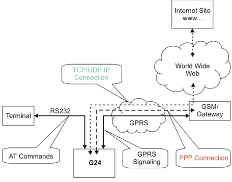
The network capabilities are achieved by using different layers of connections. Every layer of connections provides basic connections to the layer above it. The higher the layer is, the more capabilities it can provide.
Figure 1-1: System Overview
The three layers of connections are:
•
Physical links•
Point-to-point links•
TCP/UDP links World Wide Web GSM/ Gateway G24 Terminal RS232 PPP Connection GPRS Signaling GPRS TCP/UDP IP Connection Internet Site www... AT Commandsenables the G24 to be a wireless end point for a TCP/IP socket. Note: The TCP protocol use the value TTL (Time to live) = 64.
Creating TCP/IP Connections
Connection from the G24 to the Web
The following occurs when creating a TCP/IP connection from the G24 to the Web:
1. The G24 connects to the GPRS network and receives an IP address (using the +MIPCALL command).
2. The G24 opens a TCP/IP stack as one of its "sockets" (it must know the target’s IP address and port number).
3. Once the connection is established, data is transferred freely in both directions (upload and download).
Connection with another G24 using the "GPRS Manager"
The following occurs when creating a TCP/IP connection with another G24 using the "GPRS Manager":
1. The OEM on the target side (server) uses the "GPRS Manager" application. When using this application the TCP/IP is external to the OEM. (External TCP stack is used).
2. The target side activates the "server application" (The term "server application" means an application that has the ability to listen on a given IP address and port number).
3. After connecting to the GPRS network, the "server" sends its IP address to the G24 using an alternative connection (for example, CSD, SMS and so on).
4. The server application listens on a known port, waiting for G24 to connect.
5. The G24 connects to the same GPRS network as the server, and receives an IP address (using the +MIPCALL command).
6. The G24 initiates a TCP/IP connection with the listening "server". (It knows the IP address and port number of the server).
7. Once the server is connected, the TCP/IP connection is created and data can be transferred freely in both directions (upload and download).
well. Therefore, UDP/IP must open a UDP stack using the MIPOPEN AT command. The connection created does not change any concept regarding the
UDP/IP known protocol (which is connectionless), this is just an easy way for the terminal to specify to the G24 which of the four possible stacks should be used.
When establishing the UDP/IP connection, the G24 is both the "initiator" and the "listener".
Creating UDP/IP Connections
Connection with another G24
The following occurs during a UDP/IP connection with another G24: 1. Side A:
–
The G24 connects to the GPRS network and receives an IP address (using the +MIPCALL command).–
The G24 opens a UDP/IP stack as one of its "sockets" (using the +MIPOPEN and selecting the protocol UDP).2. Side B:
–
The G24 connects to the GPRS network and receives an IP address (using the +MIPCALL command).–
The G24 opens a UDP/IP stack as one of its "sockets" (using the +MIPOPEN and selecting the protocol UDP).3. Side A and B previously agree on a port number, and exchange their given IP addresses via other means of connection (SMS, CSD, Voice, DB and so on).
4. The G24 sends and receives data to and from the targeted site as it knows the IP address and port number of the target.
5. Sending (accumulating) data is done using the +MIPSEND command.
6. Actual send is done using the +MIPPUSH command, by specifying the IP address and port number of the destination.
Note: Every +MIPPUSH sets the destination IP address and destination port number for the current and future transactions. These values are used for the next push if not explicitly overwritten.
Connection from the G24 (client/server) to WEB (client/server)
The following occurs when creating a UDP/IP connection from the G24 (client/server) to WEB (client/server):
1. Client side:
–
The G24 client connects to the GPRS network and receives an IP address (using the +MIPCALL command).–
The G24 opens a UDP/IP stack as one of its "sockets" (using the +MIPOPEN and selecting the protocol UDP).2. The G24 sends data to the Website, as the Web site’s IP address is known and is public, and the port number is previously agreed upon.
3. Sending (accumulating) data is done by the +MIPSEND command.
4. Actual send is done by the +MIPPUSH command by specifying the Website IP address and Website port number.
–
The IP address and port number for the specific mobile G24 should be saved in the DB. Note: Every +MIPPUSH sets the destination IP address and destination port number for thecurrent and future transactions. These values are used for the next push if not explicitly overwritten.
Features and Benefits
The TCP/UDP IP feature provides the terminal with the following benefits:
•
Up to four simultaneous protocol connections.•
Ability to pass data via the protocol stack using AT commands (command mode). This relieves the terminal from switching the RS232 to "binary mode" and back to "command mode".•
Ability to use UDP and TCP simultaneously.•
No need for protocol support from the terminal - only data sending and receiving.•
Reduced memory utilization. The G24 manages the protocol stack and therefore savesterminal memory.
Technical Description
Figure 1-1, “System Overview,” on page 1-3 displays the system overview which comprises the following links and layers:
Physical layer links:
•
The terminal is connected to the G24 using a physical RS-232 connection.•
The G24 is connected to the GGSN using a GPRS link.•
The GGSN is connected to the Internet via some sort of physical connection (usually telephone or cable).Point-to-point layer links:
•
AT command protocol is used to transfer data between the terminal and the G24.•
After authentication, the G24 is linked to the GGSN using PPP protocol.•
The GGSN is connected to its Internet service provider using some protocol. TCP / UDP layer:•
The G24 can transfer data with the WEB using either TCP/IP or UDP/IP protocols.•
The protocol stacks in the terminal or in the OEM must be managed when using TCP/IP orUDP/IP protocols. The G24 software can manage these stacks internally. This enables the G24 to relieve the terminal from the job of managing these protocols.
Note: Currently, the embedded TCP/IP feature may be used only for mobile-initiated connections. The embedded. TCP/IP feature cannot listen on a port for incoming connections.
Overview
The audio (digital and analog) feature in the G24 module involves three main issues: path (routes the current input and output devices), gain (volume management) and algorithm. For more information, refer to “Audio” on page 3-169.
Features and Benefits
The following algorithm related features are provided:
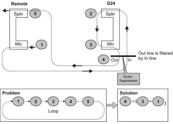
Sidetone
Sidetone reduces the microphone audio input that is routed to the selected speaker so that the person speaking can hear himself or herself talking. This creates a slight echo because the speaker sound then gets picked up again by the microphone and is again routed to the speaker, and so on. Echo suppress is designed to take care of this echo.
Figure 1-2: Sidetone
1
2
Mic Spkr
(cancels all echoes).
Figure 1-3: Echo Suppression
Noise Suppress
Noise suppression improves audio quality in all modes by suppressing environment noise from being picked up by the input device.
Technical Description
The path features provide full control over the navigation of the audio in the product.
The gain features provide full control over the volume levels of the different output accessories and tones.
The algorithm provides full control over activation/deactivation of audio quality features such as echo canceling and noise suppression.
The user can access these features by means of AT commands. These are described later in this document. Mic Spkr Echo G24 Remote 1 5 Mic Out In
Out line is filtered by In line Spkr 3 4 2 Problem Loop 1 2 3 4 5 Solution ( ( 4 3 1 Suppression
Overview
The G24 is supplied with an internal GSM 7.10 protocol stack, also referred to as a multiplexer or MUX.
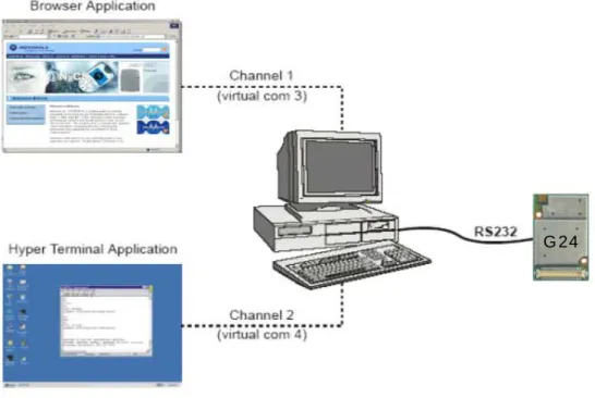
The G24 with multiplexer support utility provides the following capabilities:
•
Provides the terminal with up to five virtual channels on one physical RS-232 connection.•
Provides simultaneous data (CSD/GPRS) and command (AT command set) services. In thisway, many applications can use a single RS232 line via virtual channels. This enables a user to make network and phone service inquiries and maintain data communication at the same time.
These capabilities are illustrated in the following figure:
Figure 1-4: G24 with Multiplexer Support Capabilities
Features and Benefits
The G24 with the MUX feature ENABLES multiple channel operation and simultaneous data and control operation. For example, it allows a user to be connected to an Internet website (GPRS session connected), receive a file via CSD Call, and query the G24 phone book all at the same time.
The following actions are enabled during a data session:
•
Incoming call alert string RING (while G24 is in GPRS session)•
Answering to incoming call via the ATA command (while G24 is in GPRS session)•
Setup a voice call (while G24 is in GPRS session)•
Send & Receive SMS•
Read/write to/from Phone Book•
Local modem operation•
Network interrogation and settingsTechnical Description
The MUX feature adds five virtual channels on a single physical RS232 line:
•
Channel #0 - DLC0 for MUX Control•
Channels #1 through #4 are used for Data/Fax, GPRS, Voice call and control, and Logger/External modem applicationsOverview
The SMS feature provides means for SMS messages handling and the reporting of SMS reception events.
G24 SMS implementation is based on the GSM 07.05 specification.
Features
The SMS, as defined within the GSM 900/1800/1900 digital mobile phone standard:
•
A single short message can be up to 160 characters of ASCII text in length (7-bit coded). Message text can comprise words, numbers or an alphanumeric combination.•
Short messages can be written and displayed in various coding schemes, including ASCII and UCS2.•
Reception of an incoming message can invoke an indication to the terminal. This feature is configurable using the command AT+CNMI. Short messages received during data calls are not indicated.•
Short messages can be sent and received simultaneously with GSM voice, data and fax calls.•
Cell broadcast messages can also be selected and received on the G24. The G24 enablesThe G24 memory for incoming short messages is SIM-dependent. A new incoming message is saved in the first free memory location, from index 1, according to the SIM card.
The G24 memory can contain up to 73 outgoing and CB messages. A new outgoing message is saved in the next free memory location, from index 101 up to index 352.
SMS Type SMS Index Max Number of SMS
Incoming messages 1 SIM-dependent
2 ... 30
Future use 31 N/A
... 100 Outgoing and CB messages 101 73 102 ... 352
Overview
A Service Class 1 facsimile G24 provides a basic level of services necessary to support Group 3 facsimile operation. This requires support from the facsimile terminal to implement the
recommended T.30 procedures for document facsimile transmission and recommended T.4 for representing facsimile images.
Features and Benefits
Sending and receiving Fax services.Technical Description
Service Class 1 includes the following services, as required or optional in Group 3 facsimile:
•
Connection•
Waiting and silence detection•
Data transmission and reception•
HDLC data framing, transparency and error detection•
Message generationThe following includes the references to various tables that provide conversions between the different character sets.
•
CS1 - GSM to UCS2.•
CS2 - ASCII to/from UTF8.•
CS3 - UCS2 to/from UTF8.For the full content of a specific conversion table, refer to Appendix A, Character Set Tables.
ASCII Character Set Management
The ASCII character set is a standard seven-bit code that was proposed by ANSI in 1963, and finalized in 1968. ASCII was established to achieve compatibility between various types of data processing equipment.
GSM Character Set Management
In G24, the GSM character set is defined as octant stream. This means that text is displayed not as GSM characters but in the hex values of these characters.
UCS2 Character Set Management
UCS2 is the first officially standardized coded character set, eventually to include the characters of all the written languages in the world, as well as all mathematical and other symbols.
Unicode can be characterized as the (restricted) 2-octet form of UCS2 on (the most general) implementation level 3, with the addition of a more precise specification of the bi-directional behavior of characters, as used in the Arabic and Hebrew scripts.
The 65,536 positions in the 2-octet form of UCS2 are divided into 256 rows with 256 cells in each. The first octet of a character representation denotes the row number, the second the cell number. The first row (row 0) contains exactly the same characters as ISO/IEC 8859-1. The first 128 characters are thus the ASCII characters. The octet representing an ISO/IEC 8859-1 character is easily transformed to the representation in UCS2 by placing a 0 octet in front of it. UCS2 includes the same control characters as ISO/IEC 8859 (also in row 0).
UTF-8 Character Set Management
UTF-8 provides compact, efficient Unicode encoding. The encoding distributes a Unicode code value's bit pattern across one, two, three, or even four bytes. This encoding is a multi-byte encoding.
UTF-8 encodes ASCII in a single byte, meaning that languages using Latin-based scripts can be represented with only 1.1 bytes per character on average.
UTF-8 is useful for legacy systems that want Unicode support because developers do not have to drastically modify text processing code. Code that assumes single-byte code units typically does not fail completely when provided UTF-8 text instead of ASCII or even Latin-1.
The codes in the first half of the first row in Character Set Table CS2 (UTF-8 <-> ASCII) are replaced in this transformation format by their ASCII codes, which are octets in the range between 00h and 7F. The other UCS2 codes are transformed to between two and six octets in the range between 80h and FF. Text containing only characters in Character Set Table CS3
(UTF-8 <-> UCS-2) is transformed to the same octet sequence, irrespective of whether it was coded with UCS-2.
8859-1 Character Set Management
ISO-8859-1 is an 8 bit character set - a major improvement over the plain 7 bit US-ASCII. Characters 0 to 127 are always identical with US-ASCII and the positions 128 to 159 hold some less used control characters. Positions 160 to 255 hold language-specific characters.
ISO-8859-1 covers most West European languages, such as French (fr), Spanish (es), Catalan (ca), Basque (eu), Portuguese (pt), Italian (it), Albanian (sq), Rhaeto-Romanic (rm), Dutch (nl), German (de), Danish (da), Swedish (sv), Norwegian (no), Finnish (fi), Faroese (fo), Icelandic (is), Irish (ga), Scottish (gd) and English (en). Afrikaans (af) and Swahili (sw) are also included, extending coverage to much of Africa.
The following list contains a summary of all the G24 AT commands sorted by functionality.
Table 1-1: AT Commands
AT Command Description Page
Modem ID
Subscriber Unit Identity
+CGMI This command displays manufacturer identification. Page 3-1
+GMI This command displays manufacturer identification. Page 3-1 +FMI This command displays manufacturer identification. Page 3-1
+CGMM This command displays the model identification. Page 3-2 +GMM This command displays the model identification. Page 3-2
+FMM This command displays the model identification. Page 3-2 +CGMR This command displays the revision identification. Page 3-3
+GMR This command displays the revision identification. Page 3-3 +FMR This command displays the revision identification. Page 3-3
+CGSN This command displays the product serial number identification. Page 3-3 +GSN This command requests the product serial number identification. Page 3-3
+CSCS This command selects the G24 character set. Page 3-4
+CIMI This command displays the International Mobile Subscriber Identity number.
Page 3-6
+CFSN This command displays the factory serial number. Page 3-6 I This command displays various G24 information items. Page 3-6
+CNUM This command displays up to five strings of text information that identify the G24.
Page 3-7
$ This command displays a list of all the AT commands supported by the G24.
Page 3-8
+CLAC This command displays a list of all the AT commands supported by the G24.
Page 3-9
Call Control
Call Control Commands
D This command places a voice call on the current network, when issued from an accessory device.
Page 3-13
D> This command places a voice/fax/data call on the current network by dialing directly from the G24 pho