285
A Theoretical Model For Selection Of V-Angle
And Determination Of Firing Order For Balancing
Of V6-Engine
A. R. Barot, V. R. PatilAbstract: V-engines are subjected to noise and vibrations caused due to unbalanced inertial forces and moments, which makes its operation quite
complicated. In order to minimize these vibrations, the unbalanced forces and moments are analyzed on a reciprocating engine for different V-angles. Firing order has a great influence on balancing of engine. This paper aims at making a major contribution for selecting the angle for six cylinders V-engine based on dynamic behavior of reciprocating V-engine. V-angle and firing order is decided by primary and secondary forces and moments. But theoretical analysis of primary and secondary forces and moments is very difficult, complex and time consuming. To overcome this difficulty, a Matlab program is developed. This program calculates the various unbalanced primary and secondary forces and couples for different V-angles in V6-engine along with different possible firing order so one can select proper combination of firing order and V-angle for optimum unbalance forces and moments.
Index Terms: Balancing, Dynamics of mechanism, Firing Order, Primary and secondary forces, Primary and secondary moment, V-angle, V-engines
————————————————————
1
I
NTRODUCTIONTHE V-engine is a common configuration for internal combustion engines. The cylinders and pistons are aligned, in two separate planes or 'banks', so that they appear to be in a "V" shape when viewed along the axis of the crankshaft. The V configuration generally reduces the overall engine length, height and weight compared to an equivalent inline configuration. V-engine having an angle between two banks normally referred as bank angle or V-angle. This V-angle can be vary from 1 to 179 degrees and depending upon the number of cylinders, there may be some angles that work better than others for stability of engine. Both the V-banks are considered as two inline engines separated as V-angle. The firing order has influence on balancing of V-engine. Selection of specific firing order along with V-angle is much important as both this parameters are constructive parameter, so one has to decide before casting an engine block. This paper aims to make contribution in the selection of V-angle and firing order for dynamic stability of V-6 engine (six cylinders V-engine). Richard S. Berkof [1] explained complete force and moment balancing of inline four bar linkages. He had presented design equations and techniques which allow an inline four-bar linkage to be completely force and moment balanced, regard less of any variation of input angular velocity. J. Singh et al. [2] described the design of crankshaft for complete balancing of primary unbalanced force in reciprocating engine.
Determination of complete set of forces and moments for balanced planar four bar mechanism is explained by Brian Moore et al. [3]. Vigen H. Arakelian et al. [4] in their paper explained balancing of planar mechanisms by different methods based on the generation of the movements of counterweights. S. H. Gawande et al. [5] found that V-configuration engines are better balanced and hence V-engine will provide smooth operation, free from noise and vibration a greater extent as compared to inline engine. V-engines are less complex and more compact, and thus produce more power per unit space. Crankshafts must be balanced statically and dynamically before being put into service is explained by C. Q. Liu et al. [6]. HYMANS, F. [7] points out the necessity of obtaining dynamic or running balance of rotating parts, especially in automobile-engine construction. He discusses the manifestations of the lack of static and running balance. Formulas are supplied for calculating bending moments and centrifugal forces in a crankshaft that is out of balance. In their paper Heifetz et al. [8] have review the fundamentals of kinematics and kinetics as applied to engines. Inertia loading due to dynamic unbalance will be investigated. Equations for primary and secondary inertia vibrations will be developed for both single-cylinder and multi-cylinder engines.
2
B
ALANCING OFV-6
E
NGINE2.1V-Engine
V configurations are well-balanced and smooth, while some are less smoothly running than their equivalent straight counterparts. It is becoming more common as the space allowed for engines in modern cars is reduced at the same time as power requirements increase, and has largely replaced the inline-6, which is too long to fit in many modern engine compartments. Although it is more complicated and not as smooth as the inline 6, the V-6 is more rigid for a given weight, more compact and less prone to torsional vibrations in the crankshaft for a given displacement. Engine balancing is defined either by cylinder and cranks arrangement or by using special balancing mechanisms, which increase mass dimension parameters of the construction. The cylinder arrangement in space relative to the vertical plane is defined by the V cylinder angle, which has direct influence on the balancing parameters and, consequently, on vibrations of the _______________________________
Mrs. Ami R. Barot is currently pursuing masters degree program in Mechanical (Automobile) engineering in AISSM’s College of Engineering Pune, Pune University, India.PH 9850819006,
E-mail: [email protected].
Prof. V. R. Patil is Asst. Professor in the Department of Mechanical Engineering, AISSM’s College of Engineering, Pune, India.
286
vehicle piston engine as well. V-engines are closely linked to constructive parameters of the engine, especially the constructive angle. V-angle is very crucial factor as it immediate influence on the overall dynamics of the mechanism. An unbalance of forces is produced in rotary or reciprocating machinery due to the inertia forces associated with the moving masses. Balancing is the process of designing or modifying machinery so that the unbalance is reduced to an acceptable level and if possible is eliminated completely. The unbalance forces exerted on frame by the moving machine members are time varying, impart vibratory motion to frame and produce noise. Balancing of bodies is necessary to avoid noise and vibrations which could cause catastrophic failure of machinery. By the proper selection of firing order some V-angle gives more stability than other.
2.2 Balancing of V-twin engine
For single cylinder arrangement crank radius is r and it is rotating with constant angular velocity ω . As per Timoshenko
[9], two equivalent masses m1 and m2can conveniently
replace the connecting rod and placed at the crankpin and gudgeon pin respectively. The two conditions to be satisfied are the sum of these two masses must be equal to the total mass of the connecting rod, and their mass center must coincide with that of the rod. To the big end mass m1 is rotating mass. To the small end mass, add the masses of the piston, the rings, and the spacers, and denote the total joint
mass by m2, which is called the reciprocating mass.
Connecting rod length is l and crank makes an angle of Ө with
the stroke of piston. The inertia force for the single cylinder reciprocating mass in the direction of piston motion measured from the piston axis is,
F= m2rω2 cosӨ+r l cos 2Ө (1)
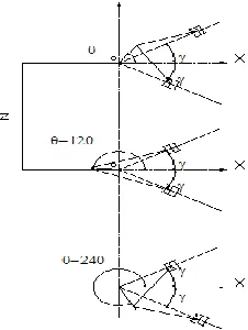
In V-twin engine two cylinders are connected with common crank and having V-angle between these two cylinder as shown in Fig.1. X axis is the bisector of V-angle. Each bank is offset by its bank angle γ referenced to the central X-axis of the engine. The crank angle ωt is measured from the Y-axis. Cylinder in the right bank is the reference cylinder.
Fig.1. Represents the V-twin engine configuration
The inertia forces for the left and right banks, in the plane of respective cylinder banks can be expressed as:
FR= ω2m
2r cos(ӨӨ+γ) +r l cos 2(ӨӨ+γ) (2)
FL= ω2m
2r cos ӨӨ−γ +r l cos 2 ӨӨ−γ (3)
The bank angle γ is added and subtracted from the crank angle for each cylinder bank to reference it to the central Y axis. The forces are directed along the planes of the cylinder banks. Substitute the following identities in (2) and (3):
cos(ӨӨ+γ) =cosӨӨcosγ−sinӨ Ө sinγ
cos(ӨӨ−γ) =cosӨӨcosγ+sinӨ Ө sinγ
Result is,
FR=
m2rω2 (cosӨӨcosγ−sinӨ Ө sinγ) +r l (cos 2ӨӨcos2γ−
sin2Ө Ө sin2γ) (4)
And
FL=
m2rω2 (cosӨ Ө cosγ + sinӨ Ө sinγ) + r l (cos 2ӨӨ cos2γ + sin2Ө Ө sin2γ) (5)
Equations (4) and (5) are Inertia forces in the left bank and right bank of V-twin. These equations are used for multi cylinder engine for further analysis.
3 Balancing analysis for V-6 engine
3.1V6-Engine
The configuration of V-6 engine is three V-twin engines or three inline engines at V-angle. For multi cylinders each bank will now be phase shifted by its bank angle as well as by the crank shaft phase angles. These two phase shifts will superpose. Taking any one cylinder in either bank, its instantaneous crank angle is represented by:
ӨӨ= ωt− ∅i (6)
In V6-engine, cranks are equally distributed in crank rotation to reduce the unbalance forces generated due to reciprocating mass and it is 120° apart from each other. The phase shift angle between the two cranks isØ . First crank is the reference crank and it is along the vertical axis. Following Fig.2 represents V-6 configuration. Distance between two
cranks or two consecutivecylinders is z.
287 3.2 Inertia forces for V-6 engine
In V-6 engine number of cylinders are 6(N=6). For this phase shifted within each bank, substitute ӨӨ = ωt − ∅i in (4) and (5). And replace the sums of angle terms with products from the identities:
cos( ωt − ∅i) = cos ωt cos∅i+ sin ωt sin∅i
sin( ωt − ∅i) = sin ωt cos∅i− cos ωt sin∅i
After manipulation the expressions for inertia forces for left
and right banks reduce to:
FR= m2rω2 (cos ωt cosγ − sin ωt sinγ)∑ cos∅i + (cos ωt sinγ + sin ωt cosγ)∑ sin∅i + r l cos 2ωt cos2γ − sin2 ωt sin2γ ∑ cos2∅i +
r l (cos 2ωt sin2γ + sin2 ωt cos2γ)∑ sin2∅i (6)
This is a combined force of primary and secondary in right bank
FPR= m2rω2 (cos ωt cosγ − sin ωt sinγ)∑ cos∅i + (cos ωt sinγ + sin ωt cosγ)∑ sin∅i
And
FSR = m2rω2 r l { cos 2ωt cos2γ − sin2 ωt sin2γ ∑ cos2∅i + (cos 2ωt sin2γ + sin2 ωt cos2γ)∑ sin2∅i }
In this FR= FPR+FSR
Similarly,
FL= m2rω2 (cos ωt cosγ + sin ωt sinγ)∑ cos∅
i −
(cos ωt sinγ − sin ωt cosγ)∑ sin∅i + r l cos 2ωt cos2γ + sin2 ωt sin2γ ∑ cos2∅i −
r l (cos 2ωt sin2γ − sin2 ωt cos2γ)∑ sin2∅i (7)
This represents combine force of primary and secondary in the left bank
FPL= m2rω2 {(cos ωt cosγ + sin ωt sinγ)∑ cos∅i − (cos ωt sinγ − sin ωt cosγ)∑ sin∅i }
FSL= m2rω2 r l { cos 2ωt cos2γ + sin2 ωt sin2γ ∑ cos2∅i − (cos 2ωt sin2γ − sin2 ωt cos2γ)∑ sin2∅i }
Now, from above forces in left and right bank, forces in the X and Y direction can be find out as shown below,
FPX= (FPL+FPR) cosγ
FSX= (FSL+FSR) cosγ
FPY= (FPL−FPR) sinγ
FSY= (FSL−FSR) sinγ (8)
Here limit of ∅i is from i=1 to N/2 i.e. 1 to 3 and crank phase is, Ø1=0°and
Ø2=120°
Ø3=240°
where,
∑ cos∅i = cos∅1+ cos∅2+ cos∅3 ∑ sin∅i = sin∅1+ sin∅2+ sin∅3
∑ cos2∅i = cos2∅1+ cos2∅2+ cos2∅3 ∑ sin2∅i = sin2∅1+ sin2∅2+ sin2∅3
3.3 Inertia moments for V-6 engine
Inertia moments for left and right bank of cylinder are given by following equations.
MR= m2rω2 (cos ωt cosγ − sin ωt sinγ)∑ zicos∅i + (cos ωt sinγ + sin ωt cosγ)∑ zisin∅i + r l cos 2ωt cos2γ
− sin2 ωt sin2γ ∑ zicos2∅i + r l (cos 2ωt sin2γ
+ sin2 ωt cos2γ)∑ zisin2∅i (9)
This is a combined moment for primary and secondary in the right bank,
MPR= m2rω2 (cos ωt cosγ − sin ωt sinγ)∑ zicos∅i
+ (cos ωt sinγ + sin ωt cosγ)∑ zisin∅i
MSR = m2rω2 r l cos 2ωt cos2γ − sin2 ωt sin2γ ∑ z icos2∅i + (cos 2ωt sin2γ
+ sin2 ωt cos2γ)∑ zisin2∅i
Similarly,
ML= m2rω2 (cos ωt cosγ + sin ωt sinγ)∑ zicos∅i − (cos ωt sinγ − sin ωt cosγ)∑ zisin∅i + r l cos 2ωt cos2γ + sin2 ωt sin2γ ∑ zicos2∅i −
r l (cos 2ωt sin2γ −
sin2 ωt cos2γ)∑ zisin2∅i (10)
Primary and Secondary moment in the left bank,
MPL = m2rω2 (cos ωt cosγ + sin ωt sinγ)∑ zicos∅i
− (cos ωt sinγ − sin ωt cosγ)∑ zisin∅i MSL = m2rω2 r l cos 2ωt cos2γ + sin2 ωt sin2γ ∑ zicos2∅i
− (cos 2ωt sin2γ
− sin2 ωt cos2γ)∑ zisin2∅i
Similar to forces, from above equations Primary and secondary moment in X and Y direction is given by,
MPX= (MPL+MPR) cosγ
MSX= (MSL+MSR) cosγ MPY= (MPL−MPR) sinγ
MSY= (MSL−MSR) sinγ (17)
where,
∑ zicos∅i = 0 ∗ cos∅1+ z ∗ cos∅2+ 2z ∗ cos∅3 ∑ zisin∅i = 0 ∗ sin∅1+ z ∗ sin∅2+ 2z ∗ sin∅3 ∑ zicos2∅i = 0 ∗ cos2∅1+ z ∗ cos2∅2+ 2z ∗ cos2∅3
∑ zisin2∅i = 0 ∗ sin2∅1+ z ∗ sin2∅2+ 2z ∗ sin2∅3
3.4 Cylinder numbering and firing order
288
would be 4-5-6) while in other number the cylinders from front to back along the crankshaft, so one bank would be 1-3-5 and the other bank would be 2-4-6. It is important to check the numbering system used before comparing firing orders, because the order will vary significantly with crankshaft design. Numbering of cylinder is in clockwise direction. The firing order is the sequence of power delivery of each cylinder in a multi cylinder reciprocating engine. This is achieved by sparking of the spark plugs in a gasoline engine in the correct order, or by the sequence of fuel injection in a Diesel engine. When designing an engine, choosing an appropriate firing order is critical to minimizing vibration, to improve engine balance and achieving smooth running, for long engine fatigue life and user comfort, and heavily
influences crankshaft design. Firing order affects
the balance, noise, vibration, smoothness, and sound of the engine. Engines have even and odd firing order. Engines that are even-firing will sound more smooth and steady, while engines that are odd or uneven firing will have a burble or a throaty, growling sound in the engine note, and, depending on the crankshaft design, will often have more vibrations due to the change of power delivery. Engines have an even firing order, mostly for quicker acceleration, less vibrations, and more efficient exhaust system designs. Although the vast majority of automobile engines rotate clockwise as viewed from the front, some engines are designed to rotate counter-clockwise to accommodate certain mechanical configurations.
3.5 Conventions:
For V6-engine, cylinder numbering is from the front of the engine and odd no of cylinders are on the right bank and even number of cylinder on the left bank. First cylinder of right bank is the reference cylinder and all the inertial forces and moments are taken as a reference vertical axis. Crankshaft rotation is anti-clockwise direction and even firing order.
Fig.3. Represents the cylinder numbering of V6- engine
To find out the influence of V-angle on the balancing of V-6 engine, following data is utilized as input parameters. This data is very near to the actual values of V-6 engine and on that basis primary and secondary forces and moments for V-6 engines are calculated for different V-angles with different
possible firing order. Manual calculations are very difficult and time consuming so a computer program in Matlab is developed for 6 cylinders.
No. Of cranks: N/2
Angle made by the first crank with the X axis is zero
Angular Positions of cranks on the crankshaft
Ø1=0°, Ø2=120° ,Ø3=240°
Mass of reciprocating parts per cylinder, m =1.487kg
Radius of crank, r =0.045m
Length of Connecting Rod, L=0.158m
Ratio of length of connecting rod to crank radius n = 3.51
N=5000 rpm
Angular velocity of crank ω =2*pi*N/60
Distance between two consecutive cylinders z =0.13 m
4 Result and Discussion
4.1 Firing order is 1-3-5-2-4-6
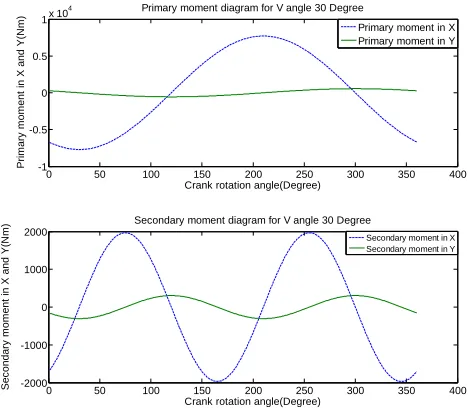
289 Fig.4 Primary and secondary moment for V angle 30°
Fig 4 represents primary and secondary moments for 30° V-angle. Here the moments are more in X direction than Y direction as the angle is small so forces are with vertical axis and secondary moments are very small as compare to primary moments it shows two peaks as the angular velocity of crank is double.
Fig.5. Primary and secondary moment for V angle 60°
Fig 5 represents primary and secondary moments for 60° V-angle. Here as the V-angle increases, the primary moments in X direction decreases and it increases in Y direction. Secondary moments are very small as compare to primary moments it shows two peaks as the angular velocity of crank is double. And for 60° both secondary moments in X and Y are equal in magnitude.
Fig.6 Primary and secondary moment for V angle 90°
Fig 6 represents primary and secondary moments for 90° V-angle. The primary moment in X direction and in Y direction is same. Secondary moment in X direction is zero and small magnitude in Y direction as compare to primary moments.
Fig.7. Primary and secondary moment for V angle 120°
Fig 7 represents primary and secondary moments for 120° V-angle. Here the moments are more in Y direction than X direction as the angle is near to Y axis, so moments are more with horizontal axis and secondary moments are very small as compared to primary moments.
0 50 100 150 200 250 300 350 400 -1
-0.5 0 0.5
1x 10
4 Primary moment diagram for V angle 30 Degree
Crank rotation angle(Degree)
Prim ary m om ent in X and Y(N m )
Primary moment in X Primary moment in Y
0 50 100 150 200 250 300 350 400 -2000
-1000 0 1000 2000
Secondary moment diagram for V angle 30 Degree
Crank rotation angle(Degree)
Sec ond ary m om ent in X and Y(N m )
Secondary moment in X Secondary moment in Y
0 50 100 150 200 250 300 350 400 -1
-0.5 0 0.5
1x 10
4 Primary moment diagram for V angle 60 Degree
Crank rotation angle(Degree)
Prim ary m om ent in X and Y(N m )
Primary moment in X Primary moment in Y
0 50 100 150 200 250 300 350 400 -1500 -1000 -500 0 500 1000 1500
Secondary moment diagram for V angle 60 Degree
Crank rotation angle(Degree)
Sec ond ary m om ent in X and Y(N m )
Secondary moment in X Secondary moment in Y
0 50 100 150 200 250 300 350 400 -5000 -3000 -1000 1000 3000 5000
Primary moment diagram for V angle 90 Degree
Crank rotation angle(Degree)
Prim ary m om ent in X and Y(N m )
Primary moment in X Primary moment in Y
0 50 100 150 200 250 300 350 400 -2000
-1000 0 1000 2000
Secondary moment diagram for V angle 90 Degree
Crank rotation angle(Degree)
Sec ond ary m om ent in X and Y(N m )
Secondary moment in X Secondary moment in Y
0 50 100 150 200 250 300 350 400 -1 -0.8 -0.6 -0.4 -0.2 0 0.2 0.4 0.6 0.8
1x 10
4 Primary moment diagram for V angle 120 Degree
Crank rotation angle(Degree)
Prim ary m om ent in X and Y(N m )
Primary moment in X Primary moment in Y
0 50 100 150 200 250 300 350 400 -2000
-1000 0 1000 2000
Secondary moment diagram for V angle 120 Degree
Crank rotation angle(Degree)
Sec ond ary m om ent in X and Y(N m )
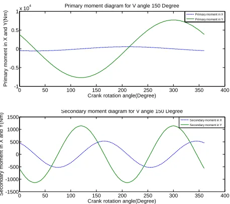
290 Fig.8. Primary and secondary moment for V angle 150°
Fig 8 represents primary and secondary moments for 150° V-angle. Here the moments are same as 30° only direction of primary and secondary moment is interchanged. Maximum magnitude of primary and secondary moments in X and Y direction for V-angle is compiled in the following table.
Table 1 Maximum Primary and Secondary moments for Different V-angles for 1-3-5-2-4-6 firing order
V-angle Mpx Mpy Msx Msy
10 8198.67 62.75 2308.37 35.61
20 8012.31 249.11 2177.45 139.74
30 7708.01 553.41 1968.27 304.49
40 7295.02 966.40 1693.75 517.28
50 6785.88 1475.54 1370.73 761.75
60 6196.07 2065.36 1018.85 1018.85
70 5543.50 2717.92 659.21 1268.20
80 4848.00 3413.42 312.99 1489.46
90 4130.71 4130.71 0.00 1663.78
100 3413.42 4848.00 262.63 1775.07
110 2717.92 5543.50 461.59 1811.18
120 2065.36 6196.07 588.23 1764.70
130 1475.54 6785.88 639.18 1633.58
140 966.40 7295.02 616.48 1421.23
150 553.41 7708.01 527.40 1136.38
160 249.11 8012.31 383.94 792.53
170 62.75 8198.67 201.96 407.03
4.2 Case II Firing order is 1-4-5-2-3-6
For V-6 engine 1-4-5-2-3-6 is the second possible firing order. For this specific firing order the primary and secondary moments for different V-angle is shown in the following figures.
Fig.9. Primary and secondary moment for V angle 30°
Fig 9 represents primary and secondary moments for 30° V-angle. The primary moment in X and Y direction is same. The secondary moments are more in X direction than Y direction as the angle is small so forces are with vertical axis.
Fig.10 Primary and secondary moment for V angle 60°
Fig 10 represents primary and secondary moments for 30° V-angle. The primary moment in X and Y direction is same. The secondary moments are more in X direction than Y direction as the angle is small so forces are with vertical axis.
0 50 100 150 200 250 300 350 400 -1
-0.5 0 0.5
1x 10
4 Primary moment diagram for V angle 150 Degree
Crank rotation angle(Degree)
Prim ary m om ent in X and Y(N m )
Primary moment in X Primary moment in Y
0 50 100 150 200 250 300 350 400 -1500 -1000 -500 0 500 1000 1500
Secondary moment diagram for V angle 150 Degree
Crank rotation angle(Degree)
Sec ond ary m om ent in X and Y(N m )
Secondary moment in X Secondary moment in Y
0 50 100 150 200 250 300 350 400 -3000 -2000 -1000 0 1000 2000 3000
Primary moment diagram for V angle 30 Degree
Crank rotation angle(Degree)
Prim ary m om ent in X and Y(N m )
Primary moment in X Primary moment in Y
0 50 100 150 200 250 300 350 400 -2000
-1000 0 1000 2000
Secondary moment diagram for V angle 30 Degree
Crank rotation angle(Degree)
Sec ond ary m om ent in X and Y(N m )
Secondary moment in X Secondary moment in Y
0 50 100 150 200 250 300 350 400 -5000 -3000 -1000 1000 3000 5000
Primary moment diagram for V angle 60 Degree
Crank rotation angle(Degree)
Prim ary m om ent in X and Y(N m )
Primary moment in X Primary moment in Y
0 50 100 150 200 250 300 350 400 -3000 -2000 -1000 0 1000 2000 3000
Secondary moment diagram for V angle 60 Degree
Crank rotation angle(Degree)
Sec ond ary m om ent in X and Y(N m )
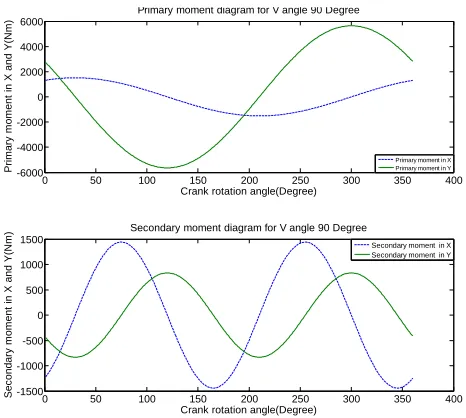
291 Fig.11 Primary and secondary moment for V angle 90°
Fig 11 represents primary and secondary moments for 90° V-angle. Here the moments are more in Y direction than X direction, so more with horizontal axis and secondary moment in x direction is more as compared Y direction.
Fig.12 Primary and secondary moment for V angle 120°
Fig 12 represents primary and secondary moments for 120° V-angle. Here the moments are more in Y direction than X direction, so more with horizontal axis and secondary moment in X direction is less as compared Y direction.
Fig.13 Primary and secondary moment for V angle 150°
Fig 13 represents primary and secondary moments for 150° V-angle. Here the moments are more in Y direction than X direction, so more with horizontal axis and secondary moment is zero in X direction and very less in Y direction.
Table 2 Maximum Primary and Secondary moments for Different V-angles for 1-4-5-2-3-6 firing order
V-angle Mpx Mpy Msx Msy
10 3478.14 652.57 1506.68 157.09
20 2782.65 1348.06 1775.07 262.63
30 2065.36 2065.36 1968.27 304.49
40 1348.06 2782.65 2077.69 275.24
50 652.57 3478.14 2100.09 172.67
60 0.00 4130.71 2037.70 0.00
70 589.81 4720.52 1898.13 234.35
80 1098.95 5229.66 1693.75 517.28
90 1511.94 5642.65 1440.87 831.89
100 1816.24 5946.95 1158.59 1158.59
110 2002.60 6133.31 867.50 1476.48
120 2065.36 6196.07 588.23 1764.70
130 2002.60 6133.31 340.10 2003.88
140 1816.24 5946.95 139.74 2177.45
150 1511.94 5642.65 0.00 2272.76
160 1098.95 5229.66 70.95 2281.99
170 589.81 4720.52 70.14 2202.62
4.3 Case III firing order is 1-6-5-4-3-2
For 1-6-5-4-3-2 firing order direct maximum primary and secondary moments for different V-angle are listed in the following table.
0 50 100 150 200 250 300 350 400 -6000 -4000 -2000 0 2000 4000 6000
Primary moment diagram for V angle 90 Degree
Crank rotation angle(Degree)
Prim ary m om ent in X and Y(N m )
Primary moment in X Primary moment in Y
0 50 100 150 200 250 300 350 400 -1500 -1000 -500 0 500 1000 1500
Secondary moment diagram for V angle 90 Degree
Crank rotation angle(Degree)
Sec ond ary m om ent in X and Y(N m )
Secondary moment in X Secondary moment in Y
0 50 100 150 200 250 300 350 400 -1 -0.8 -0.6 -0.4 -0.2 0 0.2 0.4 0.6 0.8
1x 10
4 Primary moment diagram for V angle 120 Degree
Crank rotation angle(Degree)
Prim ary m om ent in X and Y(N m )
Primary moment in X Primary moment in Y
0 50 100 150 200 250 300 350 400 -2000
-1000 0 1000 2000
Secondary moment diagram for V angle 120 Degree
Crank rotation angle(Degree)
Sec ond ary m om ent in X and Y(N m )
Secondary moment in X Secondary moment in Y
0 50 100 150 200 250 300 350 400 -6000 -4000 -2000 0 2000 4000 6000
Primary moment diagram for V angle 150 Degree
Crank rotation angle(Degree)
Prim ary m om ent in X and Y(N m )
Primary moment in X Primary moment in Y
0 50 100 150 200 250 300 350 400 -3000 -2000 -1000 0 1000 2000 3000
Secondary moment diagram for V angle 150 Degree
Crank rotation angle(Degree)
Sec ond ary m om ent in X and Y(N m )
292 Table 3 Maximum Primary and Secondary moments for
Different V-angles for 1-6-5-4-3-2 firing order
V-angle Mpx Mpy Msx Msy
10 4720.52 589.81 801.69 192.70
20 5229.66 1098.95 402.38 402.38
30 5642.65 1511.94 0.00 608.98
40 5946.95 1816.24 383.94 792.53
50 6133.31 2002.60 729.35 934.42
60 6196.07 2065.36 1018.85 1018.85
70 6133.31 2002.60 1238.92 1033.84
80 5946.95 1816.24 1380.76 972.18
90 5642.65 1511.94 1440.87 831.89
100 5229.66 1098.95 1421.23 616.48
110 4720.52 589.81 1329.09 334.69
120 4130.71 0.00 1176.47 0.00
130 3478.14 652.57 979.29 370.30
140 2782.65 1348.06 756.22 756.22
150 2065.36 2065.36 527.40 1136.38
160 1348.06 2782.65 312.99 1489.46
170 652.57 3478.14 131.82 1795.59
Table 3 represents primary moment in X direction is more as compared to Y axis and its magnitude of moment is almost three times more than Y axis. Moment in X direction is maximum at 60° and it is reduced as the angle is increased. Secondary moment at Y direction is zero at 120° and in X direction at 30°. Secondary moments are less as compared to primary moments and in Y it is zero for 120°. This firing order is considered as optimum balanced at 120°. For higher V-angle this can be preferred as the magnitude of primary moment in X is reduced drastically.
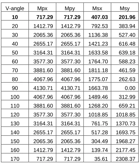
4.4 Case IV Firing order is 1-5-3-6-2-4
For 1-5-3-6-2-4 firing order direct maximum primary and secondary moments for different V-angle are listed in the following table. Following table 4 represents primary moment in X and Y direction is same for V-angle. It is maximum for 90° V-angle and it reduces as V-angle increase or decrease from 90°. Secondary moment is less compared to primary moment. For 90° secondary moment is Y direction is zero.
Table 4 Maximum Primary and Secondary moments for Different V-angles for 1-5-3-6-2-4 firing order
V-angle Mpx Mpy Msx Msy
10 717.29 717.29 407.03 201.96
20 1412.79 1412.79 792.53 383.94
30 2065.36 2065.36 1136.38 527.40
40 2655.17 2655.17 1421.23 616.48
50 3164.31 3164.31 1633.58 639.18
60 3577.30 3577.30 1764.70 588.23
70 3881.60 3881.60 1811.18 461.59
80 4067.96 4067.96 1775.07 262.63
90 4130.71 4130.71 1663.78 0.00
100 4067.96 4067.96 1489.46 312.99
110 3881.60 3881.60 1268.20 659.21
120 3577.30 3577.30 1018.85 1018.85
130 3164.31 3164.31 761.75 1370.73
140 2655.17 2655.17 517.28 1693.75
150 2065.36 2065.36 304.49 1968.27
160 1412.79 1412.79 139.74 2177.45
170 717.29 717.29 35.61 2308.37
Conclusion
From the above results it is clear that primary and secondary forces and moments are influenced by firing order and V-angle. In V-6 engine inertia forces are balanced, but primary and secondary moment in X and Y directions are unbalanced. From the above discussion it is concluded that for 1-3-5-2-4-6 firing order 90° V-angle is good. Secondary moment in X is zero and primary moment in X and Y having same magnitude so it become easy to balance such system by balancing mass. Firing order 1-4-5-2-3-6 is good for 60° V-angle as primary moment in X and secondary moment in Y direction is zero. Unbalanced forces are less compare to other V-angle so it gives more stable system. For V-angle 120°, 1-6-5-4-3-2 firing order can be used as there is primary moment only in X direction and secondary moment in Y direction. Firing order 1-5-3-6-2-4 can be use for 10° to 40° of V-angle. This work can be further extended for any number of cylinders and can be extended for the influence of piston pin offset, cylinder offset on balancing of V-engine.
References
[1] Richard S. Berkof, Complete force and moment balancing
of inline four bar linkages, Mechanism and Machine Theory, Vol. 8, no. 3, pp. 397-410, 1973.
[2] J. Singh, B. Singh, Design of crankshaft for complete balancing of primary unbalanced force in reciprocating engine, Journal of the Institution of Engineers (India), Mechanical Engineering Division.
[3] Brian Moore, Josef Schicho , Clément M. Gosselin,
293
Mechanism and Machine Theory, Vol. 44, no. 7, pp. 1338-1347, 2009.
[4] Vigen H. Arakelian and M.R.Smith , Shaking Force and
Shaking Moment Balancing of Mechanisams, ASME Trans. Journal of Mechanical Design, Vol. 127, no. 5, pp. 334-339, 2005.
[5] S. H. Gawande, L.G.Navale, Ganesh Daphal, Dynamic
vibration analysis for multicylinder diesel engine of SL90 type: International Journal of Science and Advanced Technology (ISSN 2221-8386) Volume 1 No 2 April 2011.
[6] C. Q. Liu and Jeff Orzechowski, Theoretical and Practical
Aspects of Balancing a V-8 Engine Crankshaft : 2005 SAE international (2005.01 -2454)
[7] HYMANS, F., "DYNAMIC BALANCING OF ROTATING
PARTS," SAE Technical Paper 170005, 1917,
doi:10.4271/170005.
[8] Heifetz, M. and Marsh, M., "Engine Dynamics and
Balancing," SAE Technical Paper 840914, 1984, doi:10.4271/840914.
[9] Timoshenko, S. P., Advanced Dvnamics, McGrawHill, New
York,page 136-150.
[10]Heinz Heisler, Advanced Vehicle Technology, page 79-152
[11]Diesel engine reference book second edition, ISBN 0
7860 0403 9,library of congress number 98.89287, SAE order No. R-183, Printed by The Bath Press, Bath page 219-231
[12]S. S. Ratan, Theory Of machine, third edition, Tata