R E S E A R C H
Open Access
Real-time parallel implementation of Pulse-Doppler
radar signal processing chain on a massively
parallel machine based on multi-core DSP and
Serial RapidIO interconnect
Abdessamad Klilou
1*, Said Belkouch
1, Philippe Elleaume
2, Philippe Le Gall
2, François Bourzeix
3and Moha M'Rabet Hassani
1Abstract
Pulse-Doppler radars require high-computing power. A massively parallel machine has been developed in this paper to implement a Pulse-Doppler radar signal processing chain in real-time fashion. The proposed machine consists of two C6678 digital signal processors (DSPs), each with eight DSP cores, interconnected with Serial RapidIO (SRIO) bus. In this study, each individual core is considered as the basic processing element; hence, the proposed parallel machine contains 16 processing elements. A straightforward model has been adopted to distribute the Pulse-Doppler radar signal processing chain. This model provides low latency, but communication inefficiency limits system
performance. This paper proposes several optimizations that greatly reduce the inter-processor communication in a straightforward model and improves the parallel efficiency of the system. A use case of the Pulse-Doppler radar signal processing chain has been used to illustrate and validate the concept of the proposed mapping model. Experimental results show that the parallel efficiency of the proposed parallel machine is about 90%.
Keywords:Parallel computing; Real-time processing; Pulse-Doppler radar; Digital signal processor; Serial RapidIO interconnect
1 Introduction
Radar is an object detection system. It transmits pulses of radio waves or microwaves which bounce off any object in their path, and based on the received echo, range, altitude, direction, or speed of objects can be determined.
Radar systems can be classified into two main categories depending on the used technology: primary radars or sec-ondary radars. Primary radar transmits high-frequency sig-nals which are reflected by the target and then received by the same radar. The reflected echoes will be processed to extract target information. Secondary radar, in addition to primary radar characteristics, uses a transponder on the target for responding to interrogation by transmitting a coded reply signal. We can distinguish between different techniques in primary radars. Continuous wave primary
radar transmits and receives continuously high-frequency signals, and a spatial separation between transmission and reception must be present. Pulse-Doppler radars transmit short pulses at a certain repetition frequency, and the re-ceiver and the transmitter share the antenna using a du-plexer [1].
The radar studied in this paper is Pulse-Doppler radar containing a network of uniform linear antenna and using beamforming to control the field of view of the radar. The signal processing chain applied to the received echo re-quires high-computing power to extract target informa-tion in real time [2]. A massively parallel machine with multiple processing elements that operate concurrently has been proposed in this paper to implement the totality of the signal processing chain in real-time fashion.
The parallel machine presented in this paper consists of a multi-core DSP as a basic processing element and SRIO as an inter-processor communication bus. We studied the distribution of the Pulse-Doppler radar signal processing * Correspondence:[email protected]
1
Ecole Nationale des Sciences Appliquees - Marrakech, University of Cadi Ayyad, Marrakech, Morocco
Full list of author information is available at the end of the article
chain algorithm on the proposed parallel machine. We used a straightforward model to distribute the processing on the parallel machine. The straightforward partitioning method provides low latency but generate communication inefficiency associated with the large communication group [3]. This limits the parallel efficiency of the system. The goal of this paper is to propose optimizations that re-duce the inter-processor communication in the straight-forward model and improves the parallel efficiency of the system.
We have chosen the multi-core C6678 DSP, as the basic processing element, for its low power consumption and high-performance fixed/floating point calculations [4]. C6678 DSP is an eight-core device; each core can run up to 1.25 GHz. It provides a peak performance of 160 GFLOP for a floating point and 320 GMAC for a fixed point for only 10 watts. It has been used recently by many research communities to build high-performance and low power real-time signal processing systems [2,5-11]. Add-itionally, SRIO is integrated in the C6678 DSP as a periph-eral device.
To have good performances in a multi-processor envir-onment, processors must communicate with an efficient inter-processor communication bus. This communication bus must belong to the processor-to-processor category and not to the processor-to-IO category like USB, PCI, or PCIe; it must have a high data rate and a good efficiency. Following our previous research works [12], the SRIO protocol is proposed to interconnect between DSPs in the proposed parallel machine. SRIO is a high-performance, packet-switched, interconnect technology. It was devel-oped to address the embedded industry's need in terms of faster bus speeds; increased bandwidth and reliability in an intra-system interconnect. SRIO allows chip-to-chip and board-to-board communications at performance levels scaling from 1 gigabit per second per link up to 20 Gbps [13].
We proposed an experimental platform with two C6678 DSPs, each with eight DSP cores, interconnected by SRIO, and a use case of the Pulse-Doppler radar signal processing chain to illustrate and validate the proposed optimizations.
The remainder of this paper is organized as follows. Section 2 presents recent research about SRIO and map-ping methods of radar algorithms on multi-processor systems, including a brief description of our previous work with SRIO. Section 3 introduces Pulse-Doppler radar. Section 4 describes the experimental platform. We will give an overview of the C6678 DSP, the RapidIO protocol, and the SRIO version implemented in the C6678 DSP. Then, we present the performance evalu-ation studies of SRIO. In Section 5, experiments and re-sults are presented. We will start by describing the straightforward model used to map the Pulse-Doppler radar processing chain on the parallel machine. Then we
will present all optimizations performed to the straight-forward model to improve the parallel efficiency of the system. Finally, a conclusion is provided in Section 6.
2 Related works
In recent years, many research communities were inter-ested in studying the SRIO interconnect to develop high-performance computing systems.
Adams et al. [14] have done a simulation analysis of a high-performance processing architecture based on Rapi-dIO. Two network topologies were simulated: a simple net-work consisting of an 8-port switch and 8 processing nodes and a more extensive network consisting of five 8-port switches and 24 processing nodes. Results indicate that latencies as low as 92 ns for a remote 64-bit read re-quest/response transaction may be achieved in an unloaded single-switch system.
X Zhang et al. [15] were interested in developing high-performance technologies to meet the demanding require-ment of future real-time signal processing applications. A universal, flexible, and high-performance signal processing module based on the TMS320C6455 DSP and RapidIO interconnect were developed for a next-generation, scal-able, modular, and adaptable signal-processing system such as radar jamming system. X Zhang et al. [16] have also de-veloped two kinds of flexible signal processing modules based on high-performance ADC and heterogeneous pro-cessors. They used RapidIO as an interconnect technology. The receiver module mainly consists of two 10bit 2Gsps ADCs, one TMS320C6455 DSP and one XC5V95T field-programmable gate array (FPGA). The processing module is composed of four TMS320C6455 DSPs and one XC4VSX55 FPGA. The constructed system shows the ap-plication of a multi-channel receiver, and it is scalable in resources and application.
Changrui et al. [17] have designed a high-performance heterogeneous embedded signal processing system based on the SRIO interconnection for radar systems applica-tion. The system consists of three modules which are high-speed AD module, heterogeneous processing mod-ule including FPGA and central processing unit (CPU), and RapidIO switch module. The developed system has achieved a high-performance computation with up to 550 MHz on FPGA and up to 1.5 GHz on a CPU. The system is scalable and allows future enhancements.
methods (gigabit Ethernet, SRIO, and RocketIO), can be adopted as a hardware platform for radars.
J Zhang et al. [19] have done experiments on SRIO. They have used four C6455 DSPs interconnected point-to-point by SRIO. They have measured the data rate of the communication by SRIO in direct IO mode. Experimental results show that the read and write operation can stably work at 3.125 Gbps per channel between different DSPs. The data rate obtained is up to 275 MB/s when the baud rate is 3.125 Gbps.
Xue et al. [20] have proposed a new implementation platform for parallel fast Fourier transform (FFT) called multi-core DSPs. They have used SRIO to achieve DSP-to-DSP communication and enhanced direct memory access (EDMA) to perform core-to-core communication. The proposed implementation has improved the effi-ciency of parallel FFT, especially for large points; the speed-up obtained is about 2.95 when the FFT is distrib-uted on four DSP cores.
Our previous research work [12] was addressing the performance optimization of the SRIO interconnect. We have used an experimental test bed composed of two multi-core C6474 DSPs connected by two links of SRIO V1.3. We have measured the data rate of different trans-actions proposed by SRIO in the Direct IO mode. We have also proposed three methods to transfer a data stream greater than 4 KB. Experimental results show that Nwrite and Swrite transactions achieve more perfor-mances than Nwrite_R and Nread transactions. We have determined that in order to transfer a data stream, the interrupt method is the simplest. In addition, it increases transfer robustness. The performance difference between the interrupt method and method of the EDMA in syn-chronized mode is tolerable.
Bueno et al. [3,21-25] were interested in using the RapidIO embedded interconnect in system architectures for space-based radar. They have studied two algorithms: ground moving target indicator (GMTI) and synthetic aperture radar (SAR). Their work focused on the model-ing and the simulation of RapidIO hardware and related applications using MLDesigner [26]. They have devel-oped a RapidIO test bed using Xilinx Virtex II Pro FPGA chips and boards, and a Tundra 4-port 250 MHz parallel RapidIO switch [21]. This test bed was used to calibrate the simulation models and provide the means for more complex simulation experiments using RapidIO hard-ware and advanced algorithms running on the FPGAs and/or embedded PowerPCs. The simulation work also concerned the RapidIO space systems network fault tol-erance. They have presented in [3,22] simulation results of mapping a parallel GMTI application on an embed-ded multi-processor satellite processing system using a RapidIO interconnection. Three partitioning methods of the real-time GMTI algorithm have been studied. These
methods are a straightforward approach, a staggered ap-proach, and a parallel-pipelined approach. These methods were executed on simulated systems of different sizes and topologies. In [21,23,24], they explored considerations for systems capable of executing both GMTI and SAR in real time on an embedded multi-processor satellite system equipped with a RapidIO interconnection network. In [25], they have studied chip level issues associated with the interfacing of a RapidIO network with reconfigurable processing elements through a shared SDRAM interface. They concluded that RapidIO is a promising and viable platform for space-based radar in either GMTI or SAR, with capabilities far exceeding those of traditional bus-based systems.
To our best knowledge, Bueno et al. [3,21-25] works are the closest to our research study. They have worked on the modeling and simulation of a multi-processor system based on multiple ASICs processing nodes interconnect by RapidIO bus. The system that we have proposed in this paper consists of two C6678 DSPs, each with eight DSP cores, interconnected with Serial RapidIO bus. Both sys-tems consist of different processing nodes, but both have the same architecture and use RapidIO protocol as an inter-processor communication bus. Also, Bueno et al. [3,21-25] have studied a radar application that has con-straints similar to ours in terms of high-processing power and harsh real-time needs. Finally, they have studied a straightforward approach to distribute the radar process-ing. Simulation results show that this approach provides the best performance on a RapidIO system. It produces the lowest latency, but the parallel efficiency obtained does not exceed 40% as reported in [3]. By using the straight-forward approach, data must be reorganized between processing stages (corner turn). In each corner turn, all processing elements must exchange data between each other which implies all-to-all communications. This limits the parallel efficiency of the system. We have used the same approach to distribute Pulse-Doppler radar signal processing chain algorithm on the proposed parallel machine. The major contributions of this paper are the optimization of the inter-processor communication gener-ated by the straightforward model in the corner turn stages and the improvement of the parallel efficiency of the system.
3 Background information on Pulse-Doppler radar In this section, we provide backgrounds on the Pulse-Doppler radar. All processing stages of the Pulse-Pulse-Doppler radar signal processing chain will be described.
3.1 Introduction
during which the echoes can be received, before a new transmitted signal is sent out. The transmission and the reception are alternatively managed by the same antenna using a duplexer [1]. The radar model studied in this paper is running at S band at about the frequency of 3 GHz and using beamforming to control the field of view of the radar. Typical targets of these radars are airplanes, ships, helicopters, and even missiles.
The radial speed and the distance or the height of a target can be determined from the position of the an-tenna and the propagation time.
Pulse-Doppler radar studied in this paper includes the following:
A network of uniform linear antenna which converts electrical energy into electromagnetic wave when it is used as a transmitter, or collects an
electromagnetic wave from a given direction to convert it into electrical energy when it is used as a receiver. A duplexer manages alternating
transmitting and receiving modes.
A signal processing chain is applied to the received echo to extract target information and differentiate the echo coming from a reflection on the ground, clouds, or vegetation.
The signal processing chain of Pulse-Doppler radar consists of two successive processing stages (Figure 1). The first is the coherent processing, which has as goal to maximize the signal-to-noise ratio (SNR) by focusing on the energy. The second is the post-processing which has as goal to detect and recognize targets.
3.2 Coherent processing
Coherent processing consists of three steps: beamform-ing, pulse compression, and Doppler filtering. The goal of coherent processing is to maximize the SNR by focus-ing on the energy.
3.2.1 Beamforming
Conventional antennas need to move mechanically in order to favor a direction. Antennas with a sensor network can select a field of view by applying beamforming to the received signals [27,28]. The input signal composed by the
signals received by each sensor is filtered to focus energy on a given angular direction. It is then necessary to gener-ate multiple beams, and therefore several filters to de-scribe the number of desired angular directions, and thus, obtain the desired field of view.
The beamforming is done by acting on the amplitude and the phase at each sensor. An operation of ‘delay and sum’ is commonly used; delaying incoming signals and summing them together after a multiply operation with a defined weight (Figure 2).
Beamforming algorithm can be illustrated as a com-plex matrix multiplication: Y=C X. The C matrix is composed of the beamforming complex coefficients, reflecting phase-shifting, and weighting operations. X is the input matrix composed by the received signal values from ncsensors (x1,x2,…, xnc).Y is the output matrix that will contain the formed beams (y1,y2,…,ynb) [2].
3.2.2 Pulse compression
To detect a target, the radar must emit pulses with a large amount of energy. To meet this need, pulses are very short and have high peak power. This type of signal is generated by tube amplifiers which are the only com-ponents able to ensure this power constraint in the microwave range. The disadvantages of this solution are the cost and the durability. Solid state transistors over-come those two drawbacks but do not provide a high peak power. The solution of this problem is to extend the emission time of the pulse and to reduce its peak power while maintaining the same amount of energy contained in each pulse. However, this extension of emission time brings up another problem which is reso-lution [29].
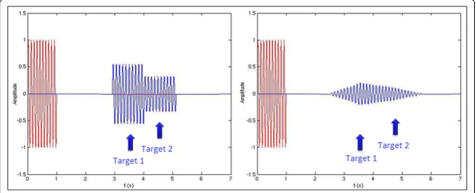
The detection is obtained by cross-correlation between the transmitted pulse and the received wave [30]. If the pulse sent by the radar is sinusoidal, two closely targets can be confused (Figure 3). To overcome this problem, the transmitted pulse is linearly frequency modulated. The signal thus obtained is called‘Chirp’(Figure 4). This improves the range resolution of the radar. Detection of two closely targets is possible (Figure 5).
Concretely, the cross-correlation is performed in the frequency domain. It is done by performing the product of the FFT of the two signals followed by the inverse fast
Fourier transform (IFFT) to return to the time domain (Figure 6).
3.2.3 Doppler filtering
Based on the Doppler effect, which specifies that the fquency shift of a wave between the transmission and re-ception is proportional to the speed of the target, this measurement is carried between successive pulses that have a significant phase shift [1]. Each Doppler filter maximizes the SNR on a single Doppler frequency. De-tection will then specify this Doppler frequency of the target and measure its radial speed.
Following the same principle as in beamforming, Doppler filtering consists on matrix multiplication:Y=C X. TheC matrix is composed of the Doppler complex coefficients. X is the input matrix composed by the received pulses values from each sensor (x1, x2,…, xnp).Yis the output matrix that will contains the formed Doppler filters (y1, y2,…,ynd).
3.2.4 Corner turn
The corner turn is an important operation in the signal processing chain of Pulse-Doppler radar. Its goal is to reorganize data between processing tasks in the coherent processing. In order to increase the locality of memory accesses within any given computational stage of the sig-nal processing chain, it is desirable to reorganize the data in memory according to the dimension that the next processing stage will operate along [31].
The corner turn constitutes the only inter-processor communications associated with the algorithm of the sig-nal processing chain of Pulse-Doppler radar. Once all data is organized properly for a given stage of signal processing chain, processing may proceed at each processing element independent of one another in an embarrassingly parallel fashion.
3.3 Post-processing
The goal of post-processing is to take decision and de-tect targets. The post-processing consists of three steps: Figure 2Beamforming structure.
Module/Log, constant false alarm rate (CFAR), and de-tection. The mapping of the post-processing will not be studied in this paper.
3.4 Data flow and real-time constraint
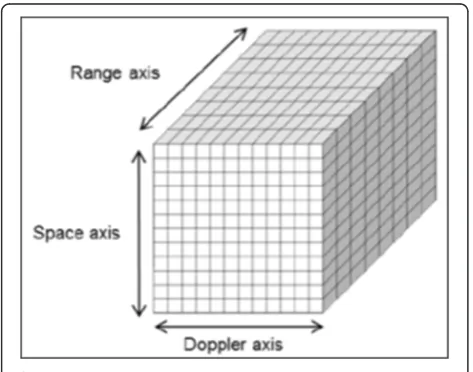
The input data processed by Pulse-Doppler radars is or-ganized as a cube of three dimensions (Figure 7). It is called a burst. The first is the space dimension consist-ing of all antenna sensors of the radars. The second is the range dimension which represents the time dimen-sion. The third is the Doppler dimension consisting of the number of pulses sent by each sensor.
Parameters of the burst that we have used in our use case are the following:
Space axis : Nc =32 channels, Nb =16 beams
Range axis : Nr =512 ranges
Doppler axis : Np =16 pulses, Nd =16 Doppler filters
Each element in the burst is a complex number coded in 8 bytes as floating number (4 bytes for real part and 4
bytes for imaginary part). The size of the input burst is equal to 2 MB.
The bursts arrive from sensors as a stream. The time be-tween the reception of each burst is equal to:TBurst=1.64 ms (TBurst= Nr × Np × 200 ns and the sampling frequency used is equal to 5 MHz (200 ns). TheTBurstis the real-time constraint for the system.
4 Description of the proposed parallel machine and the experimental platform
This section describes the experimental platform se-lected for this research work. We describe the parallel machine architecture; we give an overview about the multi-core C6678 DSP and its evaluation module. Then we describe the RapidIO embedded systems intercon-nect and the SRIO implemented like a peripheral device in the C6678 DSP. Finally, we provide results of SRIO performances studies performed to define the best way to use this interconnect.
4.1 Parallel machine's architecture
The experimental platform proposed in this paper was composed of three multi-core C6678 DSPs connected by SRIO through the SRIO Development Platform Gener-ation 2 (SRDP2) (Figure 8). The processing was distrib-uted on two DSPs (16 DSP cores). One core from the third DSP was dedicated for synchronizing, sending, and receiving bursts.
4.2 C6678 DSP overview
The multi-core C6678 DSP provided by Texas Instru-ment (TI) is a low power and a high-performance fixed/ floating point DSP based on TI's keystone multi-core architecture. It integrates eight C66x DSP cores. Each C66x DSP core can run up to 1.25 GHz. The C66x DSP Figure 4Chirp structure.
core is based on a very long instruction word (VLIW) architecture. The instruction set also includes single input multiple data (SIMD) operating up to 128-bit vectors. In our test bed, each core run at 1 GHz and dissipates 10 W of power. With eight cores running at 1GHz, the C6678 DSP has a peak performance of about 128 single precision GFLOPS (12.8 GFLOPS/watt). Figure 9 shows the func-tional block diagram of the device [4].
There are three levels of on-chip memory. Each core has a 32-KB of level 1 for program (L1P) and 32-KB of level 1 for data (L1D). The level 1 is the nearest, and it is usually used as cache memory. Additionally, each core has a local level 2 memory; it is slower than level 1, and its size is 512 KB. The level 3 or multi-core shared memory (MSM) is shared and is concurrently accessed by eight cores; its size is 4 MB. In addition to that, up to 8-Gbyte external DDR3 RAM can be accessed by the C6678 DSP through a 64-bits bus. The evaluation mod-ule EVMC6678 that we have contains 512 Mbytes of DDR3 RAM [32].
The C6678 DSP integrates several high-performance peripherals. It contains three EDMAs to transfer data between memories of the DSP without involving CPU; its bandwidth is about 15 GBPS. It also contains four lanes of the high-performances intercommunication bus SRIO Gen 2 with a baud rate up to 5 Gbps per lane, two
lanes of PCIe Gen2 with a baud rate up to 5 Gbps per lane, and two lanes of gigabit Ethernet.
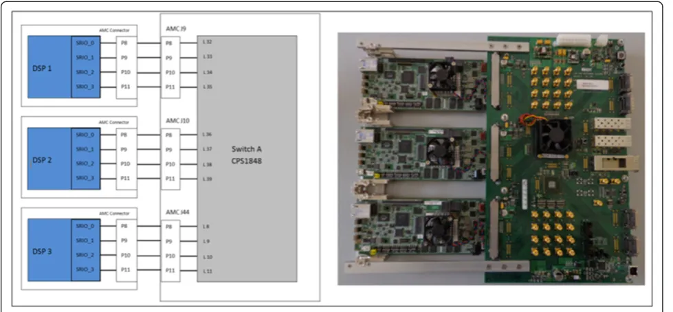
The EVM6678 evaluation module used in our test bed is a standalone development platform. It has a single-wide equivalent connectors PICMG® AMC.0 R2.0 AdvancedMC module [32] (Figure 10). It contains one TI multi-core C6678 DSP, 512 Mbytes of DDR3-1333 memory, 64 Mby-tes of NAND flash, and 16 MB SPI NOR flash. The four lanes of SRIO on the C6678 DSP are connected to the AMC port.
4.3 Description and performance evaluation of SRIO interconnect
4.3.1 RapidIO standard
The RapidIO interconnect is an open standard con-trolled by the RapidIO Trade Association. It is a high-performance, packet-switched protocol that was developed to address the embedded industry's need for faster bus speeds, increased bandwidth, reliability, cost effectiveness, and scalability. The RapidIO interconnect allows chip-to-chip, board-to-board, and chassis-to-chassis communica-tions at performance levels scaling from 1 gigabit per second per link up to 20 Gbps [13].
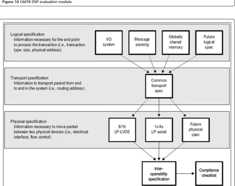
The RapidIO standard is defined as a three layer archi-tectural hierarchy (Figure 11): logical, transport, and physical. The physical layer specifies electrical signaling and link level handshaking mechanism. The transport layer defines how packets are routed in the switched fab-ric. The logical layer defines packet type and function.
Physical specification
Currently, there are two physical layer specifications rec-ognized by the RapidIO Trade Association: 8/16 LP-LVDS and 1×/4× LP-Serial. The 8/16 LP-LVDS specification is a point-to-point synchronous clock-sourcing DDR interface. The 1×/4× LP-Serial specification is a point-to-point, AC coupled, clock-recovery interface. The two physical layer specifications are not compatible.
Transport specification
The transport layer is used to define how packets are rou-ted in a RapidIO switch fabric. In RapidIO protocol, de-vices are assigned an 8 or 16 bits device ID. This device ID is integrated in the RapidIO packet as part of a header field. RapidIO switches look at an incoming packet's de-vice ID and determine the correct output port based on internal lookup table.
Logical specification
The RapidIO logical layer defines the packet types that are supported. Actually, there are three main logical layer specifications: I/O systems, message passing, and global shared memory.
Figure 7Burst structure.
Figure 9Functional block diagram of the C6678 DSP.
Figure 11RapidIO architectural hierarchy.
The I/O systems specification defines packet types and transactions used for direct memory access (DMA) type transactions. Packet types include operations such as read, write, write-with-response, streaming write, maintenance, and atomic operations. This mode of intercommunication is an extension to a processor's internal DMA. In the I/O systems mode, RapidIO packet contains the specific ad-dress where the data should be stored or read in the des-tination device. Because of that, the I/O systems mode requires that a RapidIO source device keep a local table of addresses for memory within the destination device.
Message passing specification implements a data push model, where data is always written. In this mode, the local device receives a packet and transfers the payload to its memory system.
RapidIO global shared memory logical layer supports cache coherent non-uniform memory access (CC-NUMA) systems [33].
4.3.2 SRIO implemented in C6678 DSP
The C6678 DSP includes SRIO like a peripheral device. It implements the RapidIO Interconnect Specification REV2.1.1 compliant. The physical layer supported is the LP-Serial Specification REV2.1.1 compliant [34]; it uses SerDes technology to perform clock recovery from the data stream and incorporates 8-bits/10-bits encoding.
The C6678 DSP integrates four lanes of SRIO. These lanes can operate as one 4× port, two 2× port, and four 1× ports. Each 1x port can run at frequency of 1.25, 2.5, 3.125, and 5 Gbps. Due to the 8-bits/10-bits encoding overhead, the effective data bandwidth per differential pair is 1.0, 2.0, 2.5, and 4 Gbps.
The C6678 DSP implements two specifications of the RapidIO logical layer: I/O systems and message pass-ing; global shared memory is not implemented. The I/O systems mode implemented in the C6678 DSP is called direct I/O.
Direct I/O mode defines six basic I/O operations: Nwrite, Swrite, Nread, Nwrite_R, Atomic, and mainten-ance RapidIO transaction. In this paper, we were inter-ested in Nwrite, Swrite, Nread, and Nwrite_R. These four transactions can be separated into two groups: posted transactions and non-posted transactions. Posted transac-tions are Nwrite and Swrite. They are called posted trans-actions because they do not have responses or receipt confirmation. The Nwrite and Swrite transactions are write and streaming-write operations. The Swrite tion is a double-word-only version of the Nwrite transac-tion that has fewer headers. Non-posted transactransac-tions are Nread and Nwrite_R. They are called non-posted transac-tions because they have responses. These responses may Figure 12SRIO performances in direct I/O mode with one lane at the baud rate 5 Gbps.
Table 1 Execution time on a single DSP core
Processing stage Execution time
measured before optimization (μs)
Execution time measured after optimization (μs)
Beamforming 4 088 4 261
Corner turn 1 5 377 0
Pulse compression 5 907 5 907
Corner turn 2 1 060 1 060
Doppler Filtering 2 524 2 697
Corner turn 3 5 373 0
contain data as in the case of a reading transaction or not in the case of a write transaction. The Nread transaction is a read operation. The Nwrite_R transaction is a write-with-response operation.
4.3.3 SRDP2 overview
The SRDP2 from Integrated Device Technology (IDT) is a flexible test platform for SRIO Gen2 switches. It con-tains two SRIO switches (CPS1848 and SPS1616), three AMC connectors, two SFP + connectors, one QSFP con-nector, four InfiniBand/CX4 connectors, and many SMA arrays [35].
Each AMC connector of the SRDP2 contains four lanes of SRIO from the CPS1848 switch. By connecting three evaluation modules EVM6678 to the three AMC port of the SRDP2, the four lanes SRIO of each C6678 DSP will be connected to the CPS1848 switch (Figure 8).
4.3.4 SRIO performances optimization
SRIO proposes various communication modes and trans-action types in its logical layer. Because of that it was
necessary to evaluate the performances of the intercon-nect and to define the best way to use it.
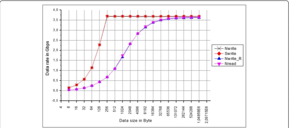
We have done a series of measurements to evaluate the SRIO performances in direct I/O mode. We have measured performances of posted transactions (Swrite and Nwrite) and non-posted transactions (Nread and Nwrite_R) by sending several packets from one C6678 DSP to another through the CPS1848 SRIO switch using the SRDP2. The transfer was done with different sizes using one SRIO lane at the maximal baud rate supported which is 5 Gbps. In direct I/O mode implemented by TI, it is possible to trans-fer up to 1 MB of data using a single transaction.
Results presented in Figure 12 show that posted transac-tions achieve better performances than non-posted trans-actions when the size of the transferred data is less than 64 KB. This result is due to the fact that non-posted trans-actions require waiting for a response. But when size of the transferred data is greater than 64 KB, performances of posted and non-posted transactions are very close. This result can be explained by an implementation improve-ment, performed by TI to optimize the SRIO on the C66x Figure 13EDMA performance.
DSP family, that allow better throughput for non-posted transactions with higher packet size.
The Swrite transaction is a little more efficient than the Nwrite transaction. Its header is smaller than the Nwrite transaction. The Swrite transaction achieves a maximal data rate of 3.70 Gbps while the Nwrite trans-action achieves a maximal data rate of 3.67 Gbps.
When the size of the transferred data is greater than 256 bytes, the Swrite transaction achieves its maximal data rate. But when the size of the transferred data is
lower than 256 bytes, the Swrite transaction performances are degraded. This is due to the fact that the minimal pay-load that can be sent by one SRIO packet is equal to 256 bytes. So to have greater efficiency with SRIO, the trans-ferred data must be higher than 256 bytes.
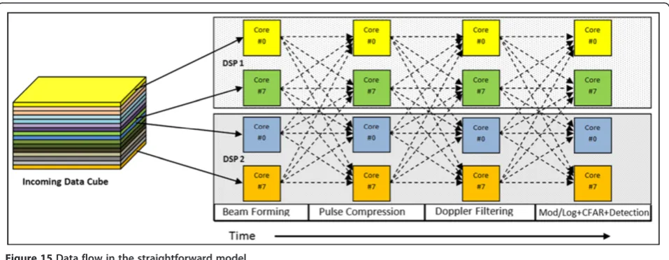
By considering the 8-bits/10-bits encoding at the phys-ical layer and the 20 bytes of overhead added to the pay-load, the theoretical data rate at the baud rate 5 Gbps is equal to 3.71 Gbps. The data rate measured with Swrite transaction is very close to the theoretical data rate. Figure 15Data flow in the straightforward model.
Following this performance evaluation studies, the Swrite transaction has been chosen for data transfers greater than 256 bytes between all DSPs at high data rate.
5 Optimization of Pulse-Doppler radar processing to parallel architecture
In this section, we present our experiments and research results that we have performed to map the Pulse-Doppler radar signal processing chain on the proposed parallel ma-chine. We present mapping results on a single DSP core to prove the need of parallel processing. Then, we in-troduce the straightforward model used to distribute the Pulse-Doppler radar signal processing chain on the paral-lel machine, and we present all optimizations that we have proposed to reduce the communication time by SRIO. Finally, we give implementation results.
5.1 Mapping results of the use case on a single DSP core We start our mapping study by implementing the use case processing on a single core of the C6678 DSP. Code devel-opment has been done using the integrated develdevel-opment environment (IDE) Code Composer Studio (CCS) provided by the TI. All optimization levels were active for the TI
compiler (7.3.2 version). Due to the size taken by the input burst, all input and output bursts have been placed in MSM memory, while coefficients are in L2 memory. L1 has been fully activated as cache.
Beamforming and Doppler filtering, which are based on a matrix product, have been implemented and optimized using C-intrinsic SIMD instructions. TI C-intrinsic allows access to low-level assembly and constrains the compiler to choose specific hardware features. The pulse compres-sion is based on FFT and IFFT algorithms.
Before optimization, all corner turn stages have been im-plemented using the EDMA engine. Column 2 in Table 1 shows obtained results. The EDMA controller did not achieve high-performances to do corner turn stages be-cause it must move a large amount of small data blocks. Each small data block consists of 8 bytes: 4 bytes for real part and 4 bytes for imaginary part. We measured the per-formance of the EDMA when moving different data sizes between two memories (Figure 13), and indeed, there is a performance degradation for a small data size.
We have optimized the use case implementation by inte-grating the corner turn 1 to beamforming and the corner turn 3 to Doppler filtering (Figure 14). In each processing
loop iteration of both beamforming and Doppler filtering, instead of storing the calculated burst elements successively in the output buffer as an image of the input buffer, we have added instructions that calculate and store intended final position of each burst element in the output buffer. Al-though these added instructions cause an overhead in the processing time, it is still much lower than performing data rearrangement by the EDMA. Corner turn 2 cannot be op-timized nor integrated to the pulse compression because the latter is based on FFT and IFFT routines, which com-pute in each iteration a data block of Nr burst elements.
The execution time measured after optimization of all signal processing chain is equal to 13.9 ms (column 3 of Table 1). This value is well above the settled use case real-time constraint of 1.64 ms. Consequently, one single DSP core of the C6678 DSP is not enough to implement the use case processing in real-time fashion.
5.2 Straightforward mapping model description and optimization
In order to distribute the Pulse-Doppler radar signal pro-cessing chain algorithm on the proposed parallel machine,
Figure 18Data flow between the beamforming and pulse compression in the straightforward model after optimization.
Table 2 Communication time between the beamforming and pulse compression before optimization
Parameters Values
Number of SRIO packets to exchange between two DSP cores Nr/16 × Nb
Size of each SRIO packet 8 bytes
Time to send each SRIO packet using one lane (see Section4.3.4) 560 ns
Communication time between two DSP cores using one SRIO lane Nr/16 × Nb × 560 ns =287μs
Communication time between one DSP core and the 16 other DSP cores using one SRIO lane 287μs × 16 = 4.59 ms
Total communication time between the two DSPs using one SRIO lane 4.59 ms × 8 cores =36.72 ms
we have used a straightforward model (Figure 15) [3,21-25]. In this model, incoming data are distributed equally across each of the DSP cores, and each DSP core performs all stages of the Pulse-Doppler radar processing chain. The straightforward partitioning method provides low latency. The parallel machine must process the entire input data cube before receiving the next cube.
The algorithm of the Pulse-Doppler radar processing chain is composed of functions with no inter-processor communication during each stage. The inter-processor communication is generated in the corner turn stages. Since Pulse-Doppler radar algorithm includes three stages of corner turn, the straightforward mapping model will contain three stages of inter-processor communications. In each stage, each DSP core must exchange data with all other DSP cores which implies an all-to-all communica-tion between DSP cores. This limits the parallel efficiency of the system [3]. We proposed several optimizations to optimize the inter-processor communications by SRIO and to improve the parallel efficiency of the system.
5.2.1 Optimization of the communications between the beamforming and pulse compression in the straightforward model
The parallel machine's memory, which is constituted by all processing element memories, has a single dimen-sion. The input data is a three-dimensional cube: Nc in-dicating the number of the radar antenna sensors, Nr
for ranges axis, and Np indicating the number of pulses sent by each antenna sensor. To map the input data cube on the parallel machine's memory, input data must be aligned along a single dimension. So, there are six possible data organizations of the input data depending on which dimension input data will be aligned. For ex-ample, input data organization 1 is when input data is aligned along Nc dimension as a level 1, Np dimension in level 2, and Nr dimension in level 3. Input data organization 2 is as like input data organization 1: input data is aligned along Nc dimension as a level 1, but Nr dimension is in level 2 and Np dimension in level 3 (Figure 16).
In order to efficiently execute the first stage of the beamforming in the Pulse-Doppler radar signal process-ing chain, the input data cube must be aligned along Nc dimension to increase the locality of memory accesses and avoid making jumps when reading the data from the memory. Indeed, writing or reading data with jumps from a DDR memory significantly reduces the band-width of the DDR memory. Data organizations 3, 4, 5, and 6 are eliminated.
By choosing the data organization 1 of the data cube as input to the beamforming, the data flow between the beamforming and pulse compression is presented in Figure 17.
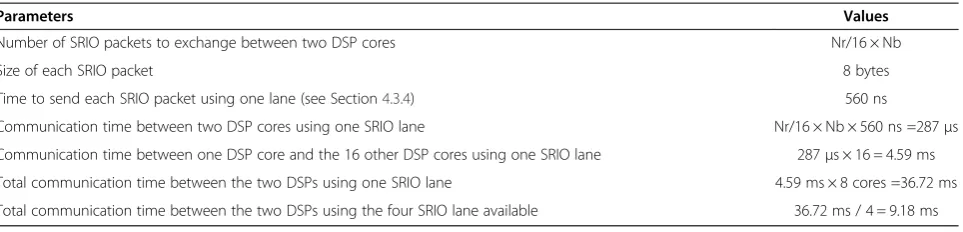
Partitioning of the beamforming is done along a range dimension. Each DSP core will process Nr/16 ranges. The SRIO communication time calculated between the beam-forming and pulse compression is about 9.18 ms (Table 2). After choosing the data organization 2 of the input data cube, the data flow between the beamforming and pulse compression will become as presented in Figure 18. In this case, partitioning of the beamforming is done along pulse dimension. Each DSP core will process one pulse. After the beamforming, DSP cores will not have to communicate
Figure 19Straightforward model after optimization of the communications between the beamforming and pulse compression.
Table 4 Communication time between the pulse compression and Doppler filtering before optimization
Parameters Values
Number of SRIO packets to exchange between two DSP cores Nr
Size of each SRIO packet 8 bytes
Time to send each SRIO packet using one lane (see Section4.3.4) 560 ns
Communication time between two DSP cores using one SRIO lane Nr × 560 ns =287μs
Communication time between one DSP core and the 16 other DSP cores using one SRIO lane 287μs × 16 = 4.59 ms
Total communication time between the two DSPs using one SRIO lane 4.59 ms × 8 cores =36.72 ms
Total communication time between the two DSPs using the four SRIO lane available 36.72 ms / 4 = 9.18 ms
between each other. They have just to rearrange data locally before starting the pulse compression. Three methods have been proposed and compared to perform this data arrangement. The first method is to integrate the data re-arrangement at the end of beamforming, the second method is to perform this data rearrangement using the EDMA, and the third one is to achieve it using CPU. From comparison study presented in Table 3, the most efficient way to perform this data rearrangement is to integrate it at the end of beamforming.
As a conclusion, by using the data organization 2 at the input of the beamforming, communications by SRIO between the beamforming and pulse compression has been eliminated (Figure 19).
5.2.2 Optimization of the communications between the pulse compression and Doppler filtering in the straightforward model
After choosing the data organization of the input data cube that optimizes communications between the beam-forming and pulse compression in the straightforward model, the data flow between the pulse compression and Doppler filtering is presented in Figure 20.
Distribution of the pulse compression is done along the pulse dimension. Each DSP core will process one pulse. The SRIO communication time calculated between the pulse compression and Doppler filtering is about 9.18 ms (Table 4). Data size sent by each SRIO packet is less than 256 bytes; SRIO is not used in an efficient way. To
Table 5 Communication time between the pulse compression and Doppler filtering after optimization
Parameters Values
Number of SRIO packets to exchange between two DSP cores 1
Size of each SRIO packet Nr × 8 bytes =4 KB
Time to send each SRIO packet using one lane (see Section4.3.4) 9μs
Communication time between two DSP cores using one SRIO lane 9μs
Communication time between one DSP core and the 16 other DSP cores using one SRIO lane 9μs × 16 = 144μs
Total communication time between the two DSPs using one SRIO lane 144μs × 8 cores =1.15 ms
Total communication time between the two DSPs using the four SRIO lane available 1.15 ms / 4 = 288μs
overcome this limitation and reduce the communication time by SRIO, we have proposed to add an intermediate stage between the pulse compression and Doppler fil-tering (Figure 21). The proposed method separates communications by SRIO between the pulse compression and Doppler filtering on two stages. The first stage sponds to SRIO communications, and the second corre-sponds to a local data rearrangement.
Communications by SRIO
In this case, the SRIO communication time calculated between the pulse compression and Doppler filtering is equal to 288μs (Table 5). SRIO in the proposed method is used in an efficient way. The data size sent by each packet is more than 256 bytes.
SRIO communications between the pulse compression and Doppler filtering can be overlapped with computation. It can be started in parallel with the pulse compression (Figure 22). Each DSP core in the straightforward model executes the pulse compression of one pulse and Nb beams. The result of the pulse compression of each beam can be sent by SRIO to another DSP core without having to wait the end of the pulse compression. Using this ap-proach, parallel machine will execute 94% of communica-tions by SRIO in parallel with the pulse compression.
Data rearrangement
The second stage in the proposed method corresponds to a local data rearrangement on each DSP core. We have proposed and compared three different methods to perform this data rearrangement. The first method is to integrate this rearrangement at the Doppler filtering, the second method is to achieve it using the EDMA, and the third one is to achieve it using the CPU.
By executing Doppler filtering of one beam on a single DSP core, the executing time when input data is well-arranged is equal to 157 μs. While when input data is not well-arranged and the data rearrangement is inte-grated to the processing, the execution time obtained is equal to 514 μs. This large difference is due to the fact of cache-coherence mechanisms which do not operate well when input data is not well-arranged.
As seen before, the C6678 DSP has three EDMA con-trollers that can operate in parallel. One EDMA can achieve the data rearrangement of one beam in 73 μs. Eight beams must be rearranged by each C6678 DSP. The three EDMA available achieve the data rearrange-ment of eight beams in 300μs.
Each DSP core executes data rearrangement of one beam in 108 μs. Since the eight DSP cores can operate in parallel, the data rearrangement of eight beams can be executed in 108μs.
From this comparison study summarized in Table 6, the efficient way to perform the data rearrangement of the second stage in the proposed method is to execute it using CPU.
As a conclusion, the proposed method which separate communications by SRIO between the pulse compres-sion and Doppler filtering into two stages has greatly op-timized communication time by SRIO.
Table 6 Comparison between data rearrangement methods
5.2.3 Optimization of the communications between the Doppler filtering and the post-processing in the straightforward model
The data flow between the Doppler filtering and the post-processing in the straightforward model after choosing a data organization that optimizes the post-processing is presented in Figure 23.
Distribution of the Doppler filtering is done along beam dimension. Each DSP core will process one beam. After Doppler filtering, DSP cores will not have to communicate between each other. They have just to rearrange data lo-cally before starting post-processing. Three methods have been proposed and compared to perform this data re-arrangement. The first method is to integrate the data rearrangement at the end of the Doppler filtering, the
second method is to perform this data rearrangement using the EDMA, and the third one is to achieve it using CPU. From the comparison study presented in Table 7, the most efficient way to perform this data rearrangement is to integrate it at the end of the Doppler filtering.
Table 7 Comparison between data rearrangement methods
Data
rearrangement methods
Data rearrangement
integrated at the Doppler
filtering
Data rearrangement using the EDMA
Data rearrangement
using CPU
Measured time (μs) 12 300 108
5.2.4 Optimization synthesis
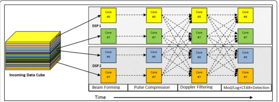
The optimizations that we have proposed to reduce inter-processor communication in the basic straightforward map-ping model have completely eliminated inter-processor communication between the beamforming and pulse com-pression, as well as between the Doppler filtering and the post-processing (Figure 24). As a result, the processing of beamforming and pulse compression, as well as the process-ing of Doppler filterprocess-ing and the post-processprocess-ing can be fused in one single block (Figure 25). The proposed optimizations have also greatly reduced inter-processor communication between the pulse compression and Doppler filtering. The parallel machine executes 94% of inter-processor communi-cation in parallel with the pulse compression.
The optimizations performed to the straightforward map-ping model are based on distributing the beamforming and
pulse compression on DSP cores along pulse dimension (Np) and distributing the Doppler filtering and the post-processing on DSP cores along beam dimension (Nb). If these two parameters change and they are not equal or not multiple of the numbers of DSP cores, one or multiple DSP cores will process multiple beams or pulses or it will stay in idle. Changing of the other parameters of the Pulse-Doppler radar signal processing chain which are number of ranges (Nr), number of channels (Nc), and number of Doppler filters (Nd) does not influence on optimizations performed to the straightforward model.
5.3 Experiments and results
The implementation results of the Pulse-Doppler radar sig-nal processing chain use case on the proposed parallel ma-chine using the straightforward model before optimization
Figure 25Straightforward model after fuse result.
are presented in Figure 26. The total processing time ob-tained is equal to 10 ms. It is much greater than the real-time constraint of the use case which is about 1.64 ms. The parallel efficiency is about 9%. The inter-processor commu-nication by SRIO takes 92% of the total processing time.
The implementation results using the optimized straight-forward model are presented in Figure 27. The obtained total processing time is equal to 0.96 ms which is lower than the real-time constraint. The parallel efficiency ob-tained is about 90%. Previous work [3,21-25] using the straightforward model to distribute a radar application on a parallel machine based on a RapidIO interconnect have achieved a parallel efficiency that does not exceed 40%.
6 Conclusions
The Pulse-Doppler radars require high-processing power. A massively parallel machine was presented in this paper with the aim to implement the Pulse-Doppler radar's sig-nal processing chain in real-time fashion. It was based on the C6678 multi-core DSP as the basic processing element and on SRIO as a high-performance inter-processor com-munication bus. We used a straightforward model to distribute the processing on the parallel machine. This model produces low latency but generates communication
inefficiency which limits the performance of the system. The major contributions of this paper are to propose opti-mizations that reduce the inter-processor communication generated by the straightforward model in the corner turn stages and to improve the parallel efficiency of the system. A use case of Pulse-Doppler radar signal processing chain and an experimental platform of a parallel machine with 16 DSP cores interconnected by SRIO have been proposed to illustrate and validate the concept of the proposed mapping model.
The proposed optimizations have greatly reduced inter-processor communication in the parallel machine. Communications between the beamforming and pulse compression, as well as between the Doppler filtering and the post-processing have been completely elimi-nated. As a result, the processing of beamforming and pulse compression, as well as the processing of Doppler filtering and the post-processing has been fused in one single block. In addition, the parallel machine executes 94% of inter-processor communication between the pulse compression and Doppler filtering in parallel with the pulse compression.
Experimental results show that the proposed parallel ma-chine and all optimizations performed to the straightforward
Figure 27Implementation results after optimization.
mapping model have allowed processing the Pulse-Doppler radar signal processing chain use case in real-time fashion. The parallel efficiency obtained is about 90%, which is much greater than 40% found in the previous work.
Competing interests
The authors declare that they have no competing interests.
Acknowledgements
This research is sponsored in part by a research and development contract from Thales Air Systems and the Moroccan Foundation for Advanced Science, Innovation, and Research.
Author details
1
Ecole Nationale des Sciences Appliquees - Marrakech, University of Cadi Ayyad, Marrakech, Morocco.2Thales Air Systems, Paris, France.3Moroccan Foundation for Advanced Science, Innovation and Research, Rabat, Morocco.
Received: 13 June 2014 Accepted: 28 October 2014 Published: 8 November 2014
References
1. DC Schleher,MTI and Pulsed Doppler Radar(Artech House, Inc, Norwood, MA, 1991) 2. M Bahtat, S Belkouch, P Elleaume, P Le Gall, Efficient implementation
scheme of a real-time radar beamformer on a VLIW DSP processor, TMS320C66x TI DSP implementation, in2012 International Conference on Complex Systems (ICCS)(IEEE, Agadir, Morocco, 2012), pp. 1–6 3. D Bueno, C Conger, A Leko, I Troxel, AD George, Virtual prototyping and
performance analysis of RapidIO-based system architectures for space-based radar, inEighth Annual Workshop on High-Performance Embedded Computing (HPEC)(Massachusetts Institute of Technology Lincoln Laboratory, Lexington, MA, USA, 2004), pp. 28–30
4. TMS320C6678 Multicore Fixed and Floating-Point Digital Signal Processor (Texas Instruments, USA, 2014). http://www.ti.com/lit/ds/symlink/ tms320c6678.pdf
5. G Yang, JD Bakos, Sparse matrix–vector multiply on the Texas Instruments C6678 digital signal processor, in2013 IEEE 24th International Conference on Application-Specific Systems, Architectures and Processors (ASAP)(IEEE, Washington, DC, USA, 2013), pp. 168–174
6. R Mego, T Fryza, Performance of parallel algorithms using OpenMP, in2013 23rd International Conference on Radioelektronika (RADIOELEKTRONIKA) (IEEE, Pardubice, Czech Republic, 2013), pp. 236–239
7. Z ZhenHuan, H Wei, T Yan, Y DaWei, W XianHong, A design of versatile image processing platform based on the dual multi-core DSP and FPGA, in 2012 Fifth International Symposium on Computational Intelligence and Design (ISCID)(IEEE, Hangzhou, China, 2012), pp. 236–239
8. M Ali, E Stotzer, FD Igual, RA van de Geijn, Level-3 BLAS on the TI C6678 multi-core DSP, in2012 IEEE 24th International Symposium on Computer Architecture and High Performance Computing (SBAC-PAD)(IEEE, New York, NY, USA, 2012), pp. 179–186
9. W Min, S Xiu-qin, The design of high performance tracking system based on multi C6678, in2012 5th International Congress on Image and Signal Processing (CISP)(IEEE, Chongqing, Sichuan, China, 2012), pp. 1348–1351 10. W Dan, M Ali, Synthetic aperture radar on low power multi-core digital
signal processor, in2012 IEEE Conference on High Performance Extreme Computing (HPEC)(IEEE, Waltham, MA, USA, 2012), pp. 1–6 11. G Chengfei, L Xiangyang, C Wenge, J Gaowei, T Haishan, Matrix
transposition based on C6678, in2012 5th Global Symposium on Millimeter Waves (GSMM)(IEEE, Harbin, Heilongjiang, China, 2012), pp. 29–32 12. A Klilou, S Belkouch, P Elleaume, P Le Gall, F Bourzeix, MM Hassani,
Performance optimization of high-speed interconnect SRIO for onboard processing, in2012 International Conference on Complex Systems (ICCS) (IEEE, Agadir, Morocco, 2012), pp. 1–6
13. RapidIO Interconnect Specification, LP-Serial Physical Layer Specification Rev. 2.1 (RapidIO Trade Association, Austin, TX, USA, 2009)
14. J Adams, C Katsinis, W Rosen, D Hecht, V Adams, HV Narravula, S Sukhtankar, R Lachenmaier, Simulation experiments of a high-performance RapidIO-based processing architecture, inIEEE International Symposium on Network Computing and Applications, 2001 (NCA 2001, 2001)(IEEE, Cambridge, MA, USA, 2001), pp. 336–339
15. X Zhang, G Liu, M Gao, A high-performance scalable computing system for real-time signal processing applications, inCongress on Image and Signal Processing, 2008 (CISP '08, 2008)(IEEE, Sanya, China, 2008), pp. 556–560 16. X Zhang, M Gao, G Liu, A scalable heterogeneous multi-processor signal
processing system based on the RapidIO interconnect, inInternational Symposium on Intelligent Information Technology Application Workshops, 2008 (IITAW '08, 2008)(IEEE, Shanghai, China, 2008), pp. 761–764
17. W Changrui, C Fan, C Huizhi, A high-performance heterogeneous embedded signal processing system based on Serial RapidIO interconnection, in2010 3rd IEEE International Conference on Computer Science and Information Technology (ICCSIT)(IEEE, Chengdu, China, 2010), pp. 611–614
18. Y Zhang, Y Wang, P Zhang, A high-performance scalable computing system on the RapidIO interconnect architecture, in2010 International Conference on Cyber-Enabled Distributed Computing and Knowledge Discovery (CyberC) (IEEE, Huangshan, China, 2010), pp. 288–292
19. J Zhang, S Hb, W Q-z, J Zhang, Research and implement of SRIO based on Mul-DSP, inConference on Computational Intelligence and Software Engineering(IEEE, Wuhan, China, 2009), pp. 1–4
20. S Xue, J Wang, Y Li, Q Peng, Parallel FFT implementation based on multi-core DSPs, in2011 International Conference on Computational Problem-Solving (ICCP) (IEEE, Chengdu, China, 2011), pp. 426–430
21. D Bueno, C Conger, A Leko, I Troxel, AD George, RapidIO-based space system architectures for synthetic aperture radar and ground moving target indicator, inNinth Annual Workshop on High-Performance Embedded Computing (HPEC) (Massachusetts Institute of Technology Lincoln Laboratory, Lexington, MA, USA, 2005), pp. 20–22
22. D Bueno, A Leko, C Conger, I Troxel, AD George, Simulative analysis of the RapidIO embedded interconnect architecture for real-time, network-intensive applications, in29th Annual IEEE International Conference on Local Computer Networks (LCN) via the IEEE Workshop on High-Speed Local Networks (HSLN)(IEEE, Tampa, Florida, USA, 2004), pp. 710–717
23. C Conger, D Bueno, AD George, Experimental analysis of multi-FPGA architectures over RapidIO for space-based radar processing, inTenth Annual Workshop on High-Performance Embedded Computing (HPEC)(Massachusetts Institute of Technology Lincoln Laboratory, Lexington, MA, USA, 2006)
24. D Bueno, C Conger, AD George, I Troxel, A Leko, RapidIO for radar processing in advanced space systems. ACM Trans. Embed. Comput. Syst.7(1), 1–38 (2007) 25. D Bueno, C Conger, AD George, Optimizing RapidIO architectures for
onboard processing. ACM Trans. Embed. Comput. Syst.9(3), 1–30 (2010) 26. G Schorcht, I Troxel, K Farhangian, P Unger, D Zinn, CK Mick, A George, H
Salzwedel, System-level simulation modeling with MLDesigner, in11th IEEE/ ACM International Symposium on Modeling, Analysis and Simulation of Computer Telecommunications Systems, 2003 (MASCOTS 2003, 2003)(IEEE, Orlando, FL, USA, 2003), pp. 207–212
27. E Brookner, Phased-array radar. Sci. Am.252, 94–102 (1985)
28. BD Van Veen, KM Buckley, Beamforming: a versatile approach to spatial filtering. IEEE ASSP Mag.5(2), 4–24 (1988)
29. PZ Peebles,Radar Principles (Wiley-India, 1998
30. F Bin Khalid, RA Amjad, MA Chohan, MM Khizar, FPGA based real-time signal processor for Pulse Doppler radar, in2012 International Conference on Informatics, Electronics & Vision (ICIEV)(IEEE, Dhaka, Bangladesh, 2012), pp. 362–366 31. H Izumi, K Sasaki, K Nakajima, H Sato, An efficient technique for corner-turn
in SAR image reconstruction by improving cache access, inProceedings International Symposium on Parallel and Distributed Processing (IPDPS 2002, 2002)(IEEE, Ft. Lauderdale, FL, USA, 2002), pp. 3–8
32. TMDXEVM6678L EVM Technical Reference Manual Version 2.0(Texas Instruments, USA, 2011). http://wfcache.advantech.com/support/ TMDXEVM6678L_Technical_Reference_Manual_2V00.pdf
33. T Scheckel, Serial RapidlO: Benefiting system interconnects, inIEEE International SOC Conference, 2005(IEEE, Herndon, VA, USA, 2005), pp. 317–318
34. KeyStone Architecture Serial RapidIO (SRIO) User Guide(Texas Instruments, USA, 2012). http://www.ti.com/lit/ug/sprugw1b/sprugw1b.pdf 35. S-RIO Development Platform Gen2(Silicon Turnkey Express, USA, 2011).
http://silicontkx.com/pdfs/SRDP2.pdf
doi:10.1186/1687-6180-2014-161