Performance Analysis for DC-DC Buck
Converter with Fuzzy and Robust Controller
Puspendu Maji1, Prof. G K. Panda2, Prof. P K. Saha3
PG Scholar, Dept. of EE, Jalpaiguri Government Engineering College, Jalpaiguri, West Bengal, India1 HOD and Professor, Dept of EE, JGEC, Jalpaiguri, West Bengal, India2
Professor, Dept of EE, JGEC, Jalpaiguri, West Bengal, India3
ABSTRACT: The switch mode power supply (SMPS) has been achieved the high power density and high performance by developing the power semiconductor devices such as IGBT, BJT, MOSFET, and GTO etc. SMPS has the capacity to handle the variable loads and variable input voltage. The efficiency, weight and size of power supplies are a great area of concern for the power supply designers. This article introduces the method of intelligent regulation to control the Buck converter using the pulse width modulation switching by a fuzzy logic and robust controller. In this paper we use the buck circuit having power MOSFET as a switch and fuzzy logic and robust controller based PWM gate signals to the switch for controlling purpose. This paper describes the design of a fuzzy logic controller using output voltage of the converter as feedback for significantly improving the dynamic performance of buck dc-dc converter by using MATLAB/ SIMULINK. In the case of robust controller, the Buck converter output voltage remains constant irrespective of load and input voltage variations from 140V to 340V.
KEYWORDS: Fuzzy logic controller, Robust controller, DC-DC buck converter, MATLAB Simulink
.
I.INTRODUCTION
The switched mode dc-dc converters are some of the simplest power electronic circuits which convert one level of electrical voltage into another level by switching action. Buck converter is widely used throughout the industry to convert a higher input voltage into a lower output voltage. This is due to their wide applications like power supplies for personal computers, office equipment, appliance control, telecommunication equipment, DC motor drives, automotive, aircraft, etc. The commonly used control methods for dc-dc converters are pulse width modulated (PWM) voltage mode control, PWM current mode control with proportional (P), proportional integral (PI), and proportional integral derivative (PID) controller. The advantages of these nonlinear controllers are their ability to react suddenly to a transient condition. The different types of nonlinear controllers are fuzzy logic controller, robust controller, hysteresis controller, sliding mode controller, boundary controller etc.
Robust control and fuzzy control techniques were used to regulate the output voltage considering the disturbances and uncertainties (input voltage and load variations) on the system. Each one of these controllers has good performance in certain operational conditions. Using robust control technique, the control signal makes the converter output response to have zero steady-state error. Robust control systems often incorporate advanced topologies which include multiple feedback loops and feed forward paths. The control lows may be represented by high order transfer functions required to simultaneously accomplish desired disturbance rejection performance with robust closed loop operation. On the other hand, using fuzzy control technique, the control signal makes the converter output voltage to have a fast transient response almost without overshoot. However, its output response has an undesirable steady-state error.
II. LITARATURE REVIEW
The dc-dc switching converters are the widely used circuits in electronics systems. They are usually used to obtain a stabilized output voltage from a given input DC voltage which is lower (buck) from that input voltage, or higher (boost) or generic (buck–boost) [1]. Most used technique to control switching power supplies is Pulse-width Modulation (PWM). The conventional PWM controlled power electronics circuits are modelled based on averaging technique and the system being controlled operates optimally only for a specific condition [2]-[3]. The linear controllers like P, PI, and PID do not offer a good large-signal transient (i.e. large-signal operating conditions) [3]-[4].
Buck converter when operated in CCM, gives a continuous output current, with smaller current ripple and low switching noise. CCM operation is usually preferred for large current applications, because it can deliver more current than the converter operating in DCM. However, a DCM converter has a much faster transient response and a loop gain that is easier to compensate than a CCM converter.
In June 2004, Perry and Sen proposed a design procedure that integrated linear control techniques with fuzzy logic. The small signal model for the converters and linear design techniques were used in the initial stages of fuzzy controller design. Simulation and experimental results were presented and compared with results of a digital PI controller. In July 2011, Feshki Farahani proposed a design of a fuzzy controller and comparing with PI digital controller. These comparisons show that the fuzzy controller has faster dynamic when compared with the PI digital classic.
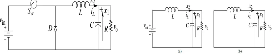
III. BASIC PRINCIPLES OF BUCK CONVERTER
The buck is a popular non-isolated power stage topology, sometimes called a step down power stage. Power supply designers choose the buck power stage because the required output is always less than the input voltage. The basic buck dc-dc converter topology consists of a controlled switch Sw, an uncontrolled switch (diode) D, an inductor L, a
capacitor C, and a load resistance R. The input current for a buck power stage is discontinuous, or pulsating. The output current for a buck power stage is continuous or non-pulsating because the output current is supplied by the output inductor/capacitor combination.
Figure 1: Buck Converter Circuit When Switch: (a) Turns On (b) Turns Off
In the description of converter operation, it is assumed that all the components are ideal and also the converter operates in CCM. In CCM operation, the inductor current flows continuously over one switching period. The switch is either on or off according to the switching function and this results in two circuit states. The first sub-circuit state is when the switch is turned on, diode is reverse biased and inductor current flows through the switch, which can be shown in figure 1(a). The second sub-circuit state is when the switch is turned off and current freewheels through the diode, which is shown figure 1(b).
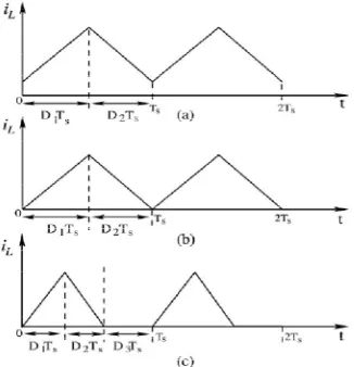
Continuous Conduction Mode: When the inductor current flow is continuous of charge and discharge during a switching period, it is called Continuous Conduction Mode (CCM) of operation shown in figure 2(a). The converter operating in CCM delivers larger current than in DCM. In CCM, each switching cycle TS consists of two parts that is
D1TS and D2TS (D1+D2= 1). During, D1TSinductor current increases linearly and then inD2TS it ramps down that is
decreases linearly.
regulated output voltage in DCM does not have a linear relationship with the input voltage as in CCM. In DCM, each switching cycle is divided into of three parts that is D1TS, D2TS and D3TS (D1 +D2 +D3 = 1). During the third mode i.e.
in D3TS, inductor current stays at zero.
Figure 2: Inductor Current Waveform (a) CCM (b) Boundary Of CCM And DCM (c) DCM
Voltage-Mode Controlled Buck Converter: The voltage feedback arrangement is known as voltage-mode control when applied to dc-dc converters. Voltage-mode control (VMC) is widely used because it is easy to design and implement, and has good community to disturbances at the references input. VMC only contains single feedback loop from the output voltage.
The voltage mode controlled buck converter circuit is shown in figure 3. It consists of a controlled switch SW
(MOSFET), an uncontrolled switch diode D (diode), an inductor L, a capacitor C, and a load resistance R. The circuit shown in figure 3 is a non-smooth dynamical system described by two sets of differential equations:
= −
,
−
,
… … 1
= − … … 2
Current-Mode Controlled Buck Converter: Current-mode controlled dc-dc converters usually have two feedback loops: a current feedback loop and a voltage feedback loop. The inductor current is used as a feedback state. At the beginning of a switching cycle, the clock signal sets the flip-flop (q=1), turning on the (MOSFET) switch. The switch current, which is equal to the inductor current iL during this interval, increases linearly. The inductor current iL is
compared with the control signal iref from the controller. When, iL is slightly greater than iref, the output of the
comparator goes high and resets the flip-flop (q=0), thereby turning off the switch. The switch will be turned on again by the next clock signal and the same process repeated.
Depending on the state of the switch, there are two circuit configurations are in the following differential equations:
= −
,
−
,
… … 3
= − … … 4
If the switch position is expressed with the switching function, then q:
= 0 1 … … 5
The control input signal is proportional to reference current iref. The reference current iref is a function of output of the
controller to regulate the output voltage.
IV.DESIGN OF FUZZY LOGIC CONTROLLER
Fuzzy Logic Membership Function
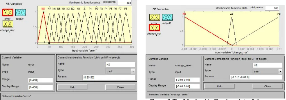
The buck dc-dc converter is a nonlinear function of the duty cycle because of the small signal model and its control method was applied to the control of buck converters. In Fuzzy controllers mathematical model is not require. Instead, they are designed based on general knowledge of the plant (converter). The Fuzzy controllers are designed to adopt the varying operating points. Fuzzy Logic Controller is designed to control the output of buck dc-dc converter. In the fuzzy logic system two input variables, error (E) and change of error (E*) and one output variable is duty cycle of PWM output are used.
For each input and output variable fuzzy sets must be defined. As shown in Fig. 5. The three fuzzy subsets N (Negative), Z (Zero), P (Positive) have been chosen for input variables error (E) and change of error (E*). The Triangular shape has been adopted for the membership functions; the value of each input and output variable is normalized in the range [0 400] by using suitable scale factors.
Figure 7: The Membership Function plots of duty ratio Figure 8: Surface View of Rules of FLC
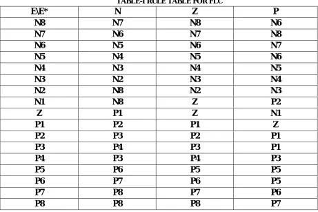
Fuzzy Logic Table Rules
Fuzzy controller rules which are playing a very important role for controller simulation are obtained from the analysis of the system behavior. In their formulation it must be considered that, by using this controller we improve the converter performances in terms of dynamic response and robustness. Suitable rules must be introduced to preventing the large overshoots. The rules of fuzzy control for error and change of error can be referred in the table 1:
TABLE-I RULE TABLE FOR FLC
E\E*
N
Z
P
N8
N7
N8
N6
N7
N6
N7
N8
N6
N5
N6
N7
N5
N4
N5
N6
N4
N3
N4
N5
N3
N2
N3
N4
N2
N8
N2
N3
N1
N8
Z
P2
Z
P1
Z
N1
P1
P2
P1
Z
P2
P3
P2
P1
P3
P4
P3
P1
P4
P3
P4
P3
P5
P6
P5
P5
P6
P7
P6
P5
P7
P8
P7
P6
P8
P8
P8
P7
Robust Controller : The robust controller is an H∞ LMI (Linear Matrix Inequality) based state feedback controller that consists in a matrix K with gains K1, K2 and K3 that multiplies the feedback states matrix x(t) – inductor current, output
techniques for minimizing the H∞ norm must find a state feedback matrix K for a set of values entered into a polytope where its vertices are formed by the uncertainty matrixes. The matrix K must satisfy the control law:
( ) = ′( ) … … … . .6
Figure 9: Block diagram for robust controller
V. SIMULATION RESULT AND DISCUSSION
Modelling in MATLAB/Sumulink For Fuzzy control Buck Converter:- This system carries out almost all the computations to produce the Output Voltage and Load Current Waveforms. The inputs to the subsystem are the Input Voltage, Duty cycle and Load Current. In addition, the following values need to be declared as masked parameters: Inductance (L), Inductance Series Resistance (RL), Capacitance (C), and Resistance (R).
Fig. 10: Simulink Model of FLC based Buck Converter
Result:--
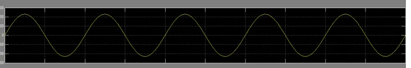
Input voltage:-- Here input voltage is 230 volt A.C
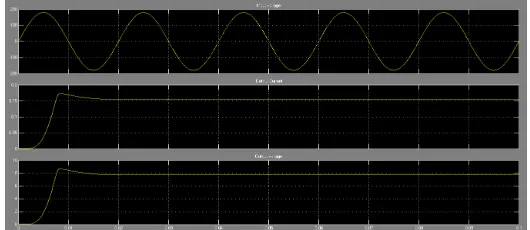
Output voltage and current:--
Figure 12: Waveform of output current and voltage
In this model, where dc-dc buck converter output voltage is controlled by the fuzzy logic controller. FLC generate a signal and it cut though the repeating sequence. Then generate a pulse which gives to mosfet. Here 230 volt ac supply pusses through a transformer and a bridge rectifier and produce dc voltage, then it step down to 10 volt. Output current is 0.5 amp.
Modelling in MATLAB/Simulink For Robust control Buck Converter:
Figure13: Simulink model for robust control buck converter
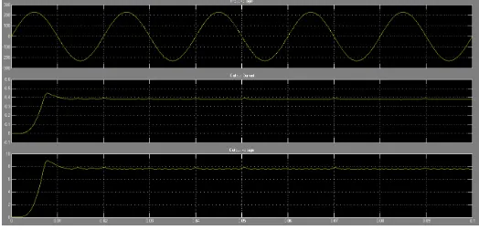
Output Result :--
SMPS operating in a Buck converter is a step down DC-DC converter controlled by robust controller used in many electronics devices. The same has been simulated by Using the MATLAB, an output voltage of 8V was obtained with an input range of 140V-340V. It does not depend on input voltage and load resistance; which is shown in the graph.
VI.CONCLUSION
Design of the fuzzy logic controller on control buck dc-dc converter by using MATLAB simulink has been successfully achieved. An algorithm based on the prediction of fuzzy logic controller, using the fuzzy rules parameter, is showing to be more convenient than the other circuit. SMPS operating in a Buck converter is a step down DC-DC converter used in many electronics devices. The same has been simulated by Using the MATLAB, an output voltage of 10V was obtained with an input range of 140V-340V DC supply. The waveforms across various points were obtained, studied and compared with the theoretical waveforms. The waveforms were found to be same to the desired waveforms. Hence, the circuit of buck dc-dc converter controlled by fuzzy logic controller confirmed the requirement of the proposed approach.
REFERENCES
[1] M. H. Rashid, Power Electronics: Circuits, Devices and Applications (3rd Edition), Prentice Hall, 2003.
[2] R.D Middlebrook and S Cuk , “A general unified approach to modeling switching Converter Power stages,” in Proc. IEEE PESC Rec., pp. 18–34, 1976.
[3] A.J. Forsyth and S.V. Mollow, “Modeling and control of dc-dc converters,” IEE power engineering journal, vol. 12, no. 5, pp. 229–236, Oct. 1998.
[4] J. T. de Carvalho Neto, A. O. Salazar, F. M. U de Araújo and A. L. O. Cavalcanti, “DSP Based Fuzzy Controller Applied to a DC-DC Boost Converter” IEEE 8th International Symposium on Intelligent Signal Processing (WISP 2013), pp. 54-59, 16-18 September 2013.
[5] S. Engell, “Design of Robust Control Systems with Time-Domain Specifications”, Control Eng. Practice, Vol.3, No.3, pp.365-372, 1995. [6] Doyle and Stein,“Robustness with Observers”, IEEE AC-24, no.4, August 1997.
[7] Q. Zhao and F. C. Lee, “High-efficiency, high step-up dc–dc converters,” IEEE Trans. Power Electron., vol. 18, no. 1, pp. 65–73, Jan. 2003. [8] V.S.C.Raviraj, P.C.Sen :Comparative study of Proportional-Integral, Sliding mode and Fuzzy Logic Controllers for Power Converters.
[9]A. Prodic, D. Maksimovic, Design of a digital PID regulator based on look-up tables for control of high-frequency dc–dc converters, in: Proceedings of IEEE Workshop on Computers in Power Electronics, 2002, pp. 18–22.
[10] Y. T. Chen and C. H. Chen, "A DC-DC Buck Converter Chip with Integrated PWM/PFM Hybrid-Mode Control Circuit", IEEE International Conference on Power Electronics and Drive Systems (PEDS 2009), pp. 181-186, 2-5 November 2009.
BIOGRAPHY
Puspendu Maji was born in West Bengal, India on March 28, 1992. He has received his B.Tech degree in Electrical Engineering from Bankura Unnayani Institute Of Engineering, Bankura, West Bengal in 2013. Currently he is persuing his M.Tech degree in Power Electronics and Drives from Jalpaiguri Govt. Engineering College, Jalpaiguri, West Bengal.
Prof.Gautam Kumar Panda, Professor and Head, Department of Electrical Engineering, Department of Electrical Engineering, Jalpaiguri Government Engineering College, Jalpaiguri,WB- 735102,BE (Electrical) from J.G.E. College, Jalpaiguri, M.E.E(Electrical) Specialization: Electrical Machines & drives from JadavpurUniversity.PhD from University of North Bengal. FIE, MISTE, Certified Energy Auditor.