886 | P a g e
Modeling and Simulation of Grid Current Controller for
Grid Connected Distributed System under Nonlinear
Loads and Voltage Distortion
Miss.Jyotsna.R wagh
1, Er.S.S.Hadape
2ME
(Student)1, Assistant Professor21,2
Electrical Engineering Department, Electrical Engineering Department
Matoshri COE &R Nashik (India)
ABSTRACT
Distributed generation is a path that employs small scale technologies to produce electricity close to the end users power. The main purpose of DG is to transmit a high quality grid current into the utility grid with the minimum total harmonic distortion of the grid current at 5%, as recommended in the IEEE 1547 standard. To produce the high quality grid current various current control strategies has been developed like hysteresis, predictive, proportional-integral (PI), proportional resonant (PR) controller. Whenever the nonlinear loads are connected to DG causes the bad impact on the grid current quality. To overcome this limitation can be developed advanced current control strategy for grid connected DG which can eliminate the effect of nonlinear load and voltage distortion. Current controller is designed using in d-q reference frame. In this paper enhanced a grid current compensator for grid connected photovoltaic under nonlinear load and voltage distortion. An advanced current control strategy for grid connected operation of distributed generation, which supports the DG to transfer a sinusoidal current into the utility grid despite the distorted grid voltage and nonlinear local load, as well as unbalanced condition.
Keywords: Distributed generation, grid connected inverter, harmonic compensation, nonlinear
load, self tuning PID controller
I.INTRODUCTION
The main source of current harmonics is nonlinear load which mostly used in system. In addition, most of these
loads impose varying reactive-power demands that have to be compensated in order to improve the power factor
(PF) and efficiently deliver the active power to the loads. This results in harmonic distortion-related problems,
reducing the quality of the electrical power and the performance of the power system. The operation of these
devices may, therefore, prove to be very problematic. Distributed energy resource (DER) systems are
small-scale power generation technologies used to provide an alternative to or an enhancement of the traditional
electric power system. The usual problems with distributed generators are their high costs. A large number of
grid connected PV connected to a distribution network through PV inverters are potentially able to cause
harmonic problems. Harmonic problem can be defined as a particular disturbance, which is created by the
887 | P a g e voltage and current sinusoidal wave shapes in terms of sinusoidal components at a frequency different from the
fundamental
In a grid-interconnected photovoltaic power system, the direct current (DC) output power of the photovoltaic
array should be converted into the alternating current (AC) power of the utility power system. Under this
condition, an inverter to convert DC power into AC power is required.
Fig.1 System configuration of a grid-connected DG system with local load.
Local load of the DG also causes a negative impact on the grid current quality. To overcome the limitation of
this this paper proposes the new current control strategy for grid connected PV.
A. System configuration and analysis of grid Voltage distortion and nonlinear local load
Fig.1 shows the proposed circuit configuration. In this system consist of DG voltage source, voltage source
inverter, output RLC filter, nonlinear local load and the utility grid. The main objective of system is to supply
power to its local load and transfer remaining power to the utility grid at the point of common coupling. The
current from DG transfer to grid should be balanced and sinusoidal and have a low THD value. Because of the
distorted grid voltage and unbalanced nonlinear load that typically exist in the power system it’s difficult to
satisfy these requirement.
II -PROPOSED SYSTEM
SVPW M
abc dq
PI-RC current Controller
Current reference Generation Local
Load
abc dq
PLL
LPF Cf
Lf Idg,abc Ig,abc
IL,abc
Ig,dq
Vg,abc PCC
Utility Grid
P*
Q* Igd
Igd*
Igq*
Igq Vgd
Vgq
Vg,dq
Vgd0 V*abc
0s 6
V*fd
V*fq Vdc
0s
+ +
+
+ +
-grid
Fig.2 Overall block diagram of the proposed control strategy.
In order to transfer sinusoidal grid current ig into the grid, DG current should include the harmonic components
that can compensate the load current harmonics. Therefore, it is important to design an effective and low-cost
current controller that can generate the specific harmonic components to compensate the grid current harmonics.
Generally, traditional current controllers, such as the PI or PR controllers, cannot realize this demand because
they lack the capability to regulate harmonic components. So we designed the proposed current controller in d-q
888 | P a g e Fig 2 shows the proposed control strategy proposed control strategy is the combination of Current reference
generation, Phased locked loop, and Current controller. Constant DC Voltage fed to inverter that can convert the
DC to AC,Converted AC are not purely sinusoidal that DG current passes through LC filter which eliminate the
harmonic part come form DG.afterthat current passes to local load,that may be balanced linear nonlinear or
unbalanced load.abc and dq0 transformation are used to convert the three phase component to two phase
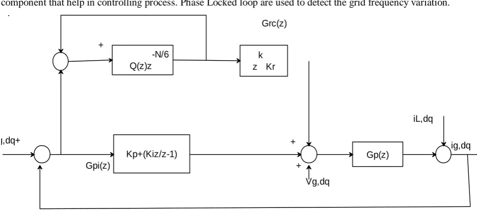
component that help in controlling process. Phase Locked loop are used to detect the grid frequency variation.
-N/6 Q(z)z
k z Kr
Kp+(Kiz/z-1) Gp(z)
Grc(z)
iL,dq
+
+ Vg,dq ig,dq+
+
Gpi(z)
ig,dq
Fig.3. Block diagram of the current controller
To enhance grid current quality, an advanced current control strategy, as shown in Fig. 2, is introduced.
Although there are several approaches to avoid the grid voltage sensors and a phase-locked loop (PLL), Fig. 3
contains the grid voltage sensor and a PLL for simple and effective implementing of the proposed algorithm,
which is developed in the d–q reference frame. The phase locked loop, current reference generation, and current
controller are three main blocks in proposed control stratergy.That strategy operates without the local load
current measurement and harmonic voltage analysis on the grid voltage. It can simultaneously adjusting
nonlinear local load and distorted grid voltage on the grid current quality.
A. Current Reference Generation
In fig.2 Current reference of current controller can be generated in the d-q reference frame based on the desired
power and grid voltage.
(1)
889 | P a g e Under ideal conditions, the magnitude of Vgd has a constant value in the d–q reference frame because the grid voltage is pure sinusoidal. However, if the grid voltage is distorted, the magnitude of Vgd no longer can be a constant value. As a consequence, reference current i∗gd and i∗gq cannot be constant in (1). To overcome this problem, a low-pass filter (LPF) is used to obtain the average value of Vgd, and the d–q reference currents are modified as follows:
(2)
B.Current Controller
Proposed current controller is design using a PI and RC in the d-q reference frame. The block diagram of current
controller is shown in fig 3.The open loop transfer function of the PI-RC in a discrete time domain is
respectively in
(3)
(4)
Where,
Kp=Proportional Gain and
Ki =Integral Gain of PI Controller
Z−N/6 = Time delay unit,
zk=phase lead term,
Q(z) = filter transfer function,
Kr= RC gain.
The RC is used to eliminate the harmonic components in the grid current caused by the unbalanced nonlinear
local load and/or distorted grid voltage. Meanwhile, the role of the PI controller is to enhance the dynamic
response of the grid current and to stabilize the whole control system.
In this paper, the proposed current controller is basically designed to compensate both the current harmonic and
the grid frequency variation, simultaneously. When the grid frequency varies, the grid frequency (fs) is quickly
detected by the PLL,and the frequency variation is compensated directly by adjusting the number of delay
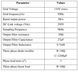
890 | P a g e C.Parameters Specification
Parameter Values
Grid Voltage 110V (rms)
Grid frequency(fs) 50Hz
Rated output power 5Kw
DC-Link voltage (Vdc) 350V
Sampling Frequency 9kHz
Output filter resistance 30Ω
Output Filter Capacitance 27µF
Output Filter Inductance 0.7mH
Three phase diode rectifier R=30Ω
C=2200µF
Phase lead term (zk) 3
Three phase linear load R=30Ω
.
Table I IV-SIMULATION MODEL AND RESULT
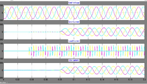
Simulation done in MALAB software to verify the effectiveness of the proposed control Method. System
parameter given in Table 1.We can done the simulation for the grid voltage distortion and nonlinear unbalanced
Rf Lf
Cf
T hree Phase Di ode Recti fi er
Discre te , Ts = 5e -005 s.
powe rgui dq0 sin_cos abc dq0_to_abc Transformation abc sin_cos dq0 abc_to_dq0 Transformation1 abc sin_cos dq0 abc_to_dq0 Transformation A B C + -z 1 Uni t Del ay
A B C a b c Three-Phase Breaker1 A B C a b c Three-Phase Breaker
A B C a b c
Three-Phase V-I Measurement2 A B C a b c Three-Phase V-I Measurement1 A B C a b c Three-Phase V-I Measurement A B C Three-Phase Series RLC Load
In1 Out1 Out2 Subsystem3 In1 Out1 Out2 Subsystem2 A B C Subsystem1 Scope Product1 Product g A B C + -Inverter [pul ses] Goto6 [Igq] Goto5 [Igd] Goto4 [Vgdo] Goto3 [Vgq] Goto2 [Vgd] Goto1 [thetas] Goto -K-Gai n3 -K-Gai n2 2/3 Gai n1 2/3 Gai n Il abc From9 Igabc From8 Vgabc From7 [pul ses] From6 [Vgq] From5 [Vgd] From4 [Igq] From3 [Igd] From2 Igabc From11 Idgabc From10 [Vgdo] From1 Vgabc From f(u) Fcn1 f(u) Fcn Ualpha Ube ta Pulse s
Discrete SV PWM Generator Fo=100Hz Discrete 2nd-Order Filter Vabc(pu) Fre q wt Sin_C os Discrete 3-phase PLL 2e3 Constant1 3e3 Constant Add3 Add2 Add1 Add
891 | P a g e Three phase programmable voltage source are used as the grid where we can apply the voltage is 110V
connected with the three phase line with photovoltaic source as distributed generation PV cell are connected
with DC source and universal bridge to forming a distributed generation. Low pass filter are used to filter out
the current and voltage harmonic in the circuit as well as it give the average value of Vd0. Diode rectifier used
as nonlinear load. Current passes through load is measured by voltage measurement parameter iL..To eliminate
the effect of nonlinear load current controller are designed that is proportional –integral proportional-resonant
controllers are designed.
Fig 5.Subsystem block for provide grid voltage distortion
To eliminate the effect of nonlinear load and voltage distortion we designed the proposed current controller. Fig
5.3.is the subsystem block are connected to the three phase line as a programmable voltage source, where the
five sine wave block are connected to the adder with Gains that give the result distorted grid voltage at the end
892 | P a g e XII. DISCUSSIONS
Simulation work carried out in MATLAB assuming grid voltage as distorted and unbalanced nonlinear load
.This case provide the distorted grid voltage is given with the harmonic components 3.5% .In this simulation
works used the constant voltage as a input connected to grid, and developed current compensator for grid
connected DG when the grid voltage distortion present and unbalanced nonlinear load condition. Three phase
breaker are connected before inverter which helps to see result before controller and after controller.
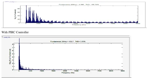
TABLE 2: Summary of THD value of grid current before controller and after controller
Before current Controller After PI-RC current Controller
THD of
Ig 195.74% 3.85%
FFT Analysis
Before Controller
With PIRC Controller
V.CONCLUSION
This paper work studied the performance of grid connected system under different load condition. When the
grid connected under different load condition and also providing the disturbance in voltage the current and
voltage harmonic are present in the system. To eliminate or reduced the effect of that harmonic this studied is
done. In that case we compare without controller and proposed control strategy. Simulation result of proposed
current controller is better than previous one. It can be easily integrated with convectional control scheme.
PI-RC current controller can reduced the number of sensor used and maintains the better quality of grid current
893 | P a g e REFERENCES
[1] R. C. Dougan and H. W. Beaty, Electrical Power Systems Quality. New York, USA: McGraw-Hill, 2002.
[2] F. Blaabjerg, R. Teodorescu, M. Liserre, and A. V. Timbus, “Overview of control and grid synchronization for distributed power generation systems,” IEEE Trans. Ind. Electron., vol. 53, no. 5, pp. 1398–1409, Oct.
2006.
[3] J. A. Suul, K. Ljokelsoy, T. Midtsund, and T. Undeland, “Synchronous reference frame hysteresis current control for grid converter applications,” IEEE Trans. Ind. Appl., vol. 47, no. 5, pp. 2183–2194, Sep./Oct.
2011.
[4] Q. Zeng and L. Chang, “An advanced SVPWM-based predictive current controller for three-phase inverters
in distributed generation systems,” IEEE Trans. Ind. Electron., vol. 55, no. 3, pp. 1235–1246, Mar. 2008. [5] S. Buso and P. Mattavelli, “Digital control in power electronics,” inSynthesis Lectures on Power Electronics.
San Rafael, CA, USA: Morgan & Claypool, 2006.
[6] C. A. Busada, S. Gomez Jorge, A. E. Leon, and J. A. Solsona, “Current controller based on reduced order generalized integrators for distributed generation systems,”IEEE Trans. Ind. Electron., vol. 59, no. 7, pp.
2898–2909, Jul. 2012.
[7] M. Liserre, R. Teodorescu, and F. Blaabjerg, “Multiple harmonics control for three-phase grid converter
systems with the use of PI-RES current controller in a rotating frame,”IEEE Trans. Power Electron., vol.
21, no. 3, pp. 836–841, May 2006.
[8] M. Castilla, J. Miret, A. Camacho, J. Matas, and L. G. de Vicuna, “Reduction of current harmonic distortion
in three-phase grid-connected photovoltaic inverters via resonant current control,”IEEE Trans. Ind.
Electron., vol. 60, no. 4, pp. 1464–1472, Apr. 2013.
[9] R.-J. Wai, C.-Y.Lin, Y.-C.Huang, and Y.-R. Chang, “Design of highperformance stand-alone and grid-connected inverter for distributed generation applications,” IEEE Trans. Ind. Electron., vol. 60, no. 4,pp.
1542–1555, Apr. 2013.
[10] I. J. Balaguer, Q. Lei, S. Yang, U. Supatti, and F. Z. Peng, “Control for grid-connected and intentional islanding operations of distributed power generation,”IEEE Trans. Ind. Electron., vol. 58, no. 1, pp. 147–
157, Jan. 2011.
[11] G. G. Pozzebon, A. F. Q. Goncalves, G. G. Pena, N. E. M. Mocambique, and R. Q. Machado, “Operation
of a three-phase power converter connected to a distribution system,”IEEE Trans. Ind. Electron., vol. 60,
no. 5, pp. 1810–1818, May 2013.
[12] Q.-C. Zhong and T. Hornik, “Cascaded current-voltage control to improve the power quality for a grid-connected inverter with a local load,” IEEE Trans. Ind. Electron., vol. 60, no. 4, pp. 1344–1355, Apr. 2013.
[13]Q.-N. Trinh and H.-H. Lee, “Improvement of current performance for grid connected converter under
distorted grid condition,” in Proc. IET Conf. RPG, Sep. 6–8, 2011, pp. 1–6.
[14]Y. A.-R. Mohamed and E. F. El-Saadany, “Adaptive discrete-time gridvoltagesensorless interfacing scheme for grid-connected DG-inverters based on neural-network identification and deadbeat current regulation,”