AT&T
PARTNER
®
Plus
Communications System
Release 3
Copyright © 1992 AT&T
All Rights Reserved
Printed in U.S.A.
AT&T 518-455-212
Issue 1
June 1992
Notice
Every effort was made to ensure that the information in this book was complete and accurate at the time of printing. However, information is subject to change.
Federal Communications Commission (FCC) Interference Notice
This equipment has been tested and found to comply with the limits of a Class A digital device, pursuant to Part 15 of FCC rules. These limits are designed to provide reasonable protection against harmful interference when the equipment is operated in a commercial environment. This equipment generates, uses, and can radiate radio frequency energy and, if not installed and used in
accordance with the instruction manual, may cause harmful interference to radio communications. Operation of this equipment in a residential area is likely to cause harmful interference, in which case the user will have to correct the interference at his or her own expense. For additional FCC
information, see Appendix C of this book.
Canadian Emissions Requirements
This digital apparatus does not exceed the Class A limits for radio noise emissions from digital apparatus set out in the Radio Interference Regulations of the Canadian Department of Communications.
Le present appareil numerique n'emet pas de bruits radioelectriques depassant les limites
applicables aux appareils numeriques de la classe A prescrites dans le Reglement sur le brouillage radioelectrique edicte par le ministere des Communications du Canada.
Trademarks
MLS-34D, MLS-18D, MLS-12D, MLS-12, MLS-6, Call Assistant, and SYSTIMAX are trademarks of AT&T. PARTNER, Magic on Hold, MERLIN, and PagePac are registered trademarks of AT&T.
Warranty
AT&T provides a limited warranty to this product. Refer to "AT&T Limited Warranty and Limitation of Liability" in Appendix B of this book.
Ordering Information
The order number for this book is 518-455-212. To order additional books, call 1 800 432-6600 in the U.S. and 1 800 255-1242 in Canada. For more information on how to order this and other system reference materials, see "Reference Materials" in the section entitled "About This Book." For information on ordering replacement parts, accessories, and other compatible equipment, refer to "Product Ordering Information" in Appendix B.
Support Telephone Numbers
In the continental U.S., AT&T provides a toll-free customer helpline 24 hours a day. Call
the AT&T Helpline at 1 800 628-2888 if you need assistance when programming or
using your system.
Contents
About This Guide
iii1
Overview
1-i■ Important Safety Instructions 1-ii
■ Features and Capabilities 1-1
■ System Components 1-2
■ Auxiliary Equipment 1-5
2
Programming
■ Overview
■ Hardware Considerations ■ Initial System Setup
■ Changing Settings After Installation ■ Changing Settings to Support PBX or
Centrex Services
■ System Programming Options ■ Using System Programming ■ Telephone Programming Options ■ Using Telephone Programming
2-i 2-1 2-2 2-3 2-5
2-6 2-7 2-11 2-14 2-16
3
Learning About Telephones
3-i■ System Telephones 3-1
■ Standard Telephones 3-7
■ Combination Extensions 3-10
■ Using Telephones 3-11
4
Using Auxiliary Equipment
4-i■ Overview 4-1
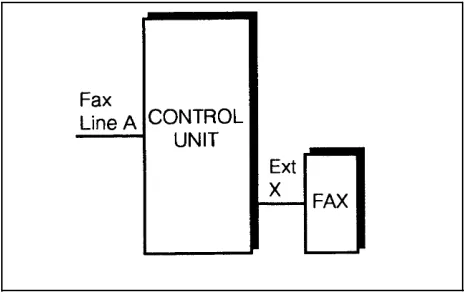
■ Fax Machines 4-3
■ Answering Machines 4-9
■ Modems 4-13
Contents
■ ■ ■ ■
Automated Attendants Credit Card Scanners
Night Service with Auxiliary Equipment Call Reporting Devices (SMDR)
4-15 4-16 4-17 4-18
5
Feature Reference
5-i6
Troubleshooting
6 - i■ When You Need Help 6 - 1
■ Power Failure Operation 6-1
■ Problems and Solutions 6-2
A
Specifications
A - 1B
Maintenance, Repair, and
Ordering Information
B - 1C
FCC Information
C - 1GL
Glossary
G L - 1About This Guide
Purpose
This guide is intended for the system manager. It explains what the PARTNER® Plus Communications System can do, provides instructions for programming and using the system, and shows you how to get the most out of its many features and capabilities.
How to Use This Guide
For advice and instructions on the following topics, refer to the appropriate chapter:
■
■
■
■
Getting Acquainted. Chapter 1 provides an overview of the system.
Read it to familiarize yourself with hardware components and system features.
Programming the System. You can change your system's settings
easily to accommodate new or expanding needs. Chapter 2 provides general information for programming the system and telephones, while Chapter 5 provides detailed instructions for programming specific system features.
Training Co-Workers. Chapter 3 explains how system and standard
phones work with the system. To help train co-workers on telephone basics, you can share this information with them. Also, give each
telephone user a Quick Reference card and a filled-in copy of the "Speed Dial" form from the System Planner.
Using Auxiliary Equipment. The system supports a wide variety of
■
■
Daily Operation. Depending on how your system is set up, you may
need to oversee some of the system's daily operations. For example, if your system is programmed to use the Night Service feature, you will need to turn on Night Service at the end of each day before leaving the office. Reference information on all features, including descriptions and instructions for using each feature, is provided in Chapter 5.
Solving Problems. Chapter 6 provides information on solving problems
if your system or telephones malfunction.
Once you are experienced with the system, use the table of Contents or Index to locate the information you need.
Product Safety Statements
Product safety statements are identified in this guide by a
CAUTION:
Indicates the presence of a hazard that will or can cause minor personal injury or property damage if the hazard is not avoided.
WARNING:
Indicates the presence of a hazard that can cause severe or fatal personal injury if the hazard is not avoided.
Reference Materials
In addition to this guide, the following materials are available (the order numbers are in parentheses):
■
■ ■
■
■
System Planner (518-455-214) provides the forms needed to plan and
record how your system and telephones are to be programmed.
Installation (518-455-213) provides instructions for installing the system. Quick Reference for Use with MLS-Series Telephones (518-455-252)
contains basic instructions for using system phones.
MLC-6 Cordless Telephone: Installation and Troubleshooting
(999-506-143) explains how to install and use the MLC-6 cordless telephone.
MLC-6 Cordless Telephone Quick Reference: Display and Controls
(999-506-146) contains basic instructions for using the MLC-6 cordless telephone.
To order these materials, call the AT&T Customer Information Center: In the continental U.S.: 1 800 432-6600
Outside the continental U.S: 1 800 255-1242
How to Comment on This Guide
Overview
1
Contents
Important Safety Instructions
1-iiFeatures and Capabilities
1-1System Components
1-2■ Control Unit 1-2
System Modules 1-2
System Capacity 1-4
■ Telephones 1-4
System Telephones 1-4
Standard Telephones 1-4
Auxiliary Equipment
1-5■ Industry-Standard Devices 1-5
Limitations 1-5
Connecting and Using Standard Devices 1-5
Important Safety Instructions
Always follow these basic safety precautions when using the system:
1.
2.
3.
4.
5.
6.
Read and understand all instructions.
Follow all warnings and instructions marked on the product.
Never spill liquid on the product or drop objects into the ventilation slots and openings. Doing so may result in serious damage to the components.
Repair or service must be performed by a qualified repair person.
The product is provided with a three-wire grounding type plug. This is a safety feature. DO NOT defeat the safety purpose of the grounding type plug. DO NOT staple or otherwise attach the AC power supply cord to building surfaces.
DO NOT use the product near water or in a wet or damp place (such as a wet basement).
CAUTION
DO NOT block or cover the ventilation slots and openings. They prevent the product from overheating. DO NOT place the product in a separate enclosure unless proper ventilation is provided.
Overview
1
Features and Capabilities
The following list provides an overview of the system's features:
■
■
■
■
■
■
■
■
■
■
Full line of MLS- and MLC-model system phones, providing access to multiple lines from a single phone at each extension.
Programmable buttons on system phones, providing one-touch access to system features simply by pressing the button.
Direct connections for industry-standard devices—including most standard phones, fax machines, answering machines, modems, and credit card scanners.
Intuitive operation of basic call handling capabilities including transfer, conference, and hold.
Intercom (inside) calling to other system extensions using an Intercom button and the two-digit number assigned to the extension. Users can either ring an extension or voice signal an extension using a system phone's speaker.
Easy-to-use programming procedures, making it easy for you to manage your system and telephones. System display phones provide feedback during programming.
Modular connections to the control unit, making it easy for you to
reconfigure your system or to add lines and/or extensions as your system grows.
Flexible dialing restrictions and permissions so you can control telephone activity and phone bills.
Group assignment of extensions for flexibility in directing and answering calls.
■
■
■
Power failure operation with standard phones, allowing you to make and receive calls during a power failure while retaining programmed
equipment settings for up to four days. (An optional Uninterruptible Power Supply, or UPS, is also available to allow full equipment operation during a power failure.)
Two system programming extensions, giving you the opportunity to set up and maintain the system from one programming extension without interrupting call activity at the other programming extension—usually the receptionist's extension.
Optional equipment support, including doorphones, hotline phones, loudspeaker paging systems, music on hold*, call reporting (often referred to as Station Message Detail Recording or SMDR) devices, automated attendants, and extra alerts.
System Components
Modular hardware design makes the system easy to install and expand. Figure 1-1 shows an example of system components.
Control Unit
The control unit is the heart of the system; it includes a backplane and a cover, and it houses the system modules.
WARNING:
There are no customer-serviceable components inside the system modules or backplane. There are hazardous voltages within that can cause severe or fatal personal injury. DO NOT OPEN THE MODULES.
System Modules
The following system modules can be installed in your system:
■
■
Processor Module provides the software intelligence that controls the
system's features. It has jacks for a music-on-hold audio source, a loudspeaker paging system, and a call reporting (SMDR) device, such as a printer.
206 Module has jacks to connect a maximum of two outside telephone
lines and six extensions to the system. You can connect telephones and other telecommunications devices (such as fax machines or modems) to the extension jacks (either directly or through your building's modular wall jacks). Each 206 module has a green power indicator that shows it is receiving power. The system requires at least one 206 module.
■ 400 Module is similar to the 206 module, but without extension jacks. It
has four outside line jacks. This module is an inexpensive way to add lines when you do not need more extensions. (If you are upgrading from
a PARTNER Communications System or a previous release of a PARTNER Plus Communications System, you can still use its 200 modules, each providing two line jacks.)
CONTROL UNIT Main Circuit Breaker Power Cord Receptacle 400 Modules PAGE Jack SMDR Jack Line Jacks
MUSIC ON HOLD Jack (for RCA phono plug) 206 Modules
Cover
Processor Module
Outside Line Jacks
Power Indicators (LEDs)
Extension Jacks (206 modules only)
AT&T PagePac®6 Paging System AT&T Call Accounting Terminal Printer AT&T Call Accounting Terminal (Basic or Plus)
AT&T
Magic on Hold® deck
Optional Devices
(that connect ot the control unit)
SYSTEM PHONES Standard Touch-Tone Phone Answering Machine MLS-34D Phone
(with optional MLS-CA24 Intercom Autodialer)
MLS-18D Phone MLS-12 Phone
Fax Machine
Bell MLS-12D Phone
Doorphone
MLS-6 Phone MLC-6 Phone
Optional Devices
(that connect to exetension jacks)
System Capacity
The combination of 206 and 400 modules installed determines the number of available lines and extensions. The system allows up to 12 lines and up to 24 extensions; however, these cannot be achieved simultaneously:
■
■
For maximum line capacity (12 lines), install two 206 modules and two 400 modules. This arrangement allows up to 12 extensions.
For maximum extension capacity (24 extensions), install four 206 modules. This arrangement allows up to 8 lines.
Telephones
System Telephones
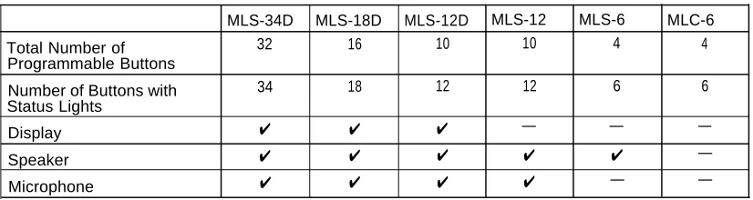
This guide refers to AT&T telephones specifically designed to work with the PARTNER Plus system as system phones. These include the MLS-34D™, MLS-18D™, MLS-12D™, MLS-12™, MLS-6™, and MLC-6 model telephones. System phones make maximum use of the system's features. The number in each model name indicates the number of buttons with status lights (including the two Intercom buttons). These buttons (excluding the two Intercom buttons) can be used for outside lines, Auto Dial numbers, or programmable features. If the phone has a display, indicated by a "D" in the model name, users will receive messages and prompts when making calls and programming. (More information about the display is provided in Chapter 5.)
In addition, system phones have several buttons in common: volume control buttons, and the Feature , Conf , Transfer , and Hold buttons. Table 1-1 summarizes system phone features.
Table 1-1. System Phones
MLS-34D MLS-18D MLS-12D MLS-12 MLS-6 MLC-6
Total Number of 32 16 10 10 4 4
Programmable Buttons
Number of Buttons with 34 18 12 12 6 6
Status Lights
Display ✔ ✔ ✔ — — —
Speaker ✔ ✔ ✔ ✔ ✔ —
Microphone ✔ ✔ ✔ ✔ — —
A system display phone is required for system programming. Make sure that the programming phone is as large as the largest phone in the system, because an MLS-12D or MLS-18D cannot program an MLS-34D. Similarly, an MLS-12D
cannot program an MLS-18D.
Standard Telephones
Auxiliary Equipment
You can connect many types of telecommunications devices to your system without expensive adapters or additional phone lines.
Industry-Standard Devices
Many industry-standard, single-line devices will work with the system regardless of the manufacturer:
■
■ ■ ■ ■
Touch-tone, rotary, and cordless telephones (such as those you might have in your home)
Fax machines Answering machines Modems
Credit card scanners
Limitations
The following limitations apply to an industry-standard device:
■
■
■
It must be non-proprietary. That is, it cannot be made specifically for use on a particular telephone system. (For example, you cannot connect an AT&T MERLIN® phone because it is specifically designed for use on a MERLIN system.)
Its Ringer Equivalence Number (REN*) cannot be greater than 2.0. (The REN is shown on a label on the device, usually on the bottom.)
You can connect a multiple-line device to the system, but for best results it should be installed and used as if it were a single-line device.
Connecting and Using Standard Devices
You can connect a standard device so that it is on an extension by itself, or so that it shares an extension with another piece of equipment (either another standard device or a system phone) as long as the REN of the two devices together does not exceed 2.0. For example, you can connect a standard phone and an answering machine to the same extension. An extension with two devices connected to it is called a combination extension. The PARTNER Plus
Communications System Installation guide provides installation instructions.
(Information about programming and using many of the standard devices is in Chapter 4 of this guide.)
Other Devices
In addition, you can connect the following devices to your system:
■
■
■
■
■
■
■
■
■ ■
■
■
■
Call Assistant™ Intercom Autodialers with Busy Indication (Model
MLS-CA24) allow the users at extensions 10 and 11 to see which extensions are busy and to automatically dial or transfer calls to other extensions.
Doorphones allow visitors to ring any number of extensions at once by
pressing a button on the doorphone; the person who answers a doorphone call can then speak with the visitor at the doorphone.
Automated attendants answer calls and route them to appropriate
extensions based on user responses to recorded messages.
Loudspeaker paging systems allow users to broadcast a message over
a large area.
Music-on-hold systems allow you to play recorded music to callers
while they are on hold.
Call accounting devices allow you to print or to store and analyze call
reports.
Extra alerts are strobes, lights, chimes, horns, or bells that light or ring
when calls come in to alert users. For example, you can use an audible alert (chime, horn, or bell) to replace a phone ring in a noisy area, such as a factory. Similarly, you can use a visual alert (strobe or light) to replace a phone ring in a quiet area, such as a library.
Speakerphones can be combined with MLS-model phones or standard
phones in conference rooms or offices, to provide an inexpensive way for people at a meeting to conference in other parties. (MLS-model phones have built-in speakers, but they are designed for individual—not
group—use.)
Headsets allow users to hold private, hands-free conversations.
Handsets for hard-of-hearing users allow even more amplification than
is provided by the volume controls on system phones.
In-Range Out-of-Building (IROB) protectors are required to prevent
electrical surges from damaging your system when phones are installed in another building, but on the same continuous property.
Electromagnetic Interference (EMI) filters allow you to block "noise"
generated by a nearby radio station, as well as most electrical devices.
Caller ID display units can display information on incoming calls, on
lines that support Caller ID service. (To get Caller ID information, you must subscribe to this service from your local telephone company.) Most of these devices can be ordered through AT&T—see "Product Ordering Information" in Appendix B for details.
Programming
2
Contents
Overview
Hardware Considerations
Initial System Setup
■ Setting the System Clock ■ Assigning Lines■ Customizing Extensions ■ Copy Settings
Changing Settings after Installation
■ Changing the System Clock■ Adding New Lines ■ Adding New Extensions ■ Swapping Extensions
Changing Settings to Support
PBX or Centrex Services
■ Recall Setting■ Dialing Restrictions
■ Speed Dial and Auto Dial Numbers
■ Standard Phones
System Programming Options
■■ ■ ■
Dialing Restrictions and Permissions Restricting Access to Outside Lines Controlling Calls on Outside Lines Overriding Dialing Restrictions Summary
Setting Up Groups of Extensions Setting Up Auxiliary Equipment System Speed Dialing
Contents
Using System Programming
■ Programming Mode■ The Programming Overlays
Telephone Programming Options
■ Automatic Line Selection■ Line Ringing
■ Personal Speed Dialing
■ Programming Telephone Buttons
■ Programming a Receptionist's Extension
■ Using a Second Programming Extension
Using Telephone Programming
■ Telephone Models■ Using Centralized Telephone Programming ■ Using Extension Programming
Programming
2
Overview
After the system hardware is installed as described in the PARTNER Plus
Communications System Installation guide, you can customize the system and
individual telephones. This chapter explains how to use programming to accomplish that.
There are two types of programming:
■
■
System Programming allows you to customize the system to meet the
needs of your business. When the system is first installed, it uses factory settings that reflect the most commonly used options. You can change system settings as needed.
You can perform System Programming from either extension 10 or 11. Because an extension cannot be in program mode and handle calls at the same time, you can program from extension 11 while the
receptionist at extension 10 continues to handle calls.
Telephone Programming allows telephones to be customized to meet
individual users' needs. Individual telephones can be programmed either from extension 10 or 11 (called Centralized Telephone Programming), or from a user's extension using a system phone (called Extension
Programming).
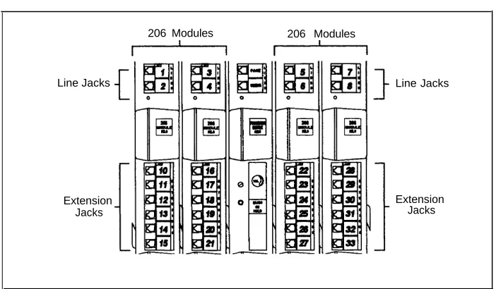
Hardware Considerations
Programming procedures use line and extension numbers. The line number represents the line jack on a 206 or 400 module that the outside line is
connected to. Similarly, the extension number represents the extension jack on a 206 module to which the system phone or standard device is connected. For each 206 module, the system assigns two lines and six extensions; for each 400 module, the system assigns four lines. The system numbers lines and extensions consecutively. Figure 2-1 shows the numbering scheme—01 through 12—for a system with maximum lines. Figure 2-2 shows the numbering scheme—10 through 33—for a system with maximum extensions. However, your system can have any number of lines and extensions up to the maximum.
206 Modules 400 Modules
Line Jacks Line Jacks
Extension Jacks
Line Jacks
Figure 2-1. Maximum Lines
206 Modules 206 Modules
Line Jacks Line Jacks
Extension Jacks
Initial System Setup
After the control unit is installed, you set up the system using a combination of system and telephone programming procedures. System Programming procedures are identified by a code (# and three digits); Telephone Programming procedures are identified by the feature name only.
Use the System Planner as a guide when programming. The following sections provide an overview of the procedures you use for initial system set up. See Chapter 5 for more information on specific procedures.
Other programming procedures are optional, but strongly recommended to make the most of your investment. (See "System Programming Options" and "Telephone Programming Options" later in this chapter for details.)
Setting the System Clock
After installing system hardware and supplying power to the control unit, set the system clock. Use the following procedures:
■ System Date (#101) to set the month and day. ■ System Day (#102) to set the day of the week. ■ System Time (#103) to set the hour and minutes.
Assigning Lines
For initial setup only, use Number of Lines (#104) to specify the number of lines that will be assigned to all system extensions Then use the following
procedures as needed:
■
■
■
■
■
Dial Mode (#201) to identify any rotary lines (the default for all lines is
"touch-tone").
Line Assignment (#301) to assign lines to specific extensions (if the line
was not assigned using the Number of Lines procedure), to remove lines from some extensions, or to change the button used to pick up a line at a specific extension.
Line Ringing (Centralized Telephone Programming) to specify when the
line will start ringing at each extension that has the line. For additional information on line ringing options, see "Programming a Receptionist's Phone" later in this chapter.
Automatic Line Selection (Centralized Telephone Programming) to
specify the order in which the system tries to select an available line (intercom or outside) for an outgoing call, when a user at the extension lifts the handset or presses Spkr to make a call without first selecting a specific line button.
Customizing Extensions
The following procedures can be used to customize an extension:
■
■
■
■
■
■
■
■
Display Language (#303) to specify the language (English, French, or
Spanish) to be used for messages that appear on a system display phone.
Automatic Extension Privacy (#304) to prevent other extensions with
the same line from joining a call at the extension. This feature is also useful for extensions connected to a modem, fax, or any device whose function can be disrupted by someone trying to join it.
Pickup Groups (#501), Calling Groups (#502), Night Service Group (#504), and Hunt Groups (#505) to place the extension in any of these
groups.
Forced Account Code Entry (#307) to prevent the extension from
making an outside call until a required account code is entered.
Outgoing Call Restriction (#401) to prevent the extension from making
certain types of outgoing calls (on all system lines).
Disallowed List Assignments (#405) to assign one or more Disallowed
Phone Number Lists to the extension. Use Disallowed Phone Number
Lists (#404) to create the lists of outside numbers that extensions cannot
dial.
Allowed List Assignments (#408) to assign an Allowed Phone Number
List to the extension. Use Allowed Phone Number Lists (#407) to create a list of outside numbers that otherwise restricted extensions can dial.
Fax Machine Extensions (#601), Doorphone 1/2 Extensions (#604/#605), Doorphone Alert Extensions (#606), or AA/VMS Extensions (#607) to identify the extension as one of these equipment
types.
"Setting Up Auxiliary Equipment" later in this chapter provides an overview of the procedures you use for setting up devices, such as hotline phones, automated attendants, and call reporting devices. Also, Chapter 4 provides detailed information and example applications for auxiliary equipment.
Copy Settings
Changing Settings after Installation
As your business grows or changes, you will probably need to change the way your system was originally programmed. This section provides some examples and lists the procedures you would use to change settings after installation. For specific details on a procedure, refer to the procedure name in Chapter 5
Changing the System Clock
You may need to change the system clock for daylight saving time, after a prolonged power failure, or after a system reset. Use System Date (#101),
System Day (#102), and System Time (#103) to set the current date, day, and
time.
Adding New Lines
If you add an outside line to your system, you may need to adjust some line settings. In particular, use Dial Mode (#201) if the new line is a rotary line, Line
Assignment (#301) to assign the line to specific extensions, Line Ringing
(Centralized Telephone Programming) to specify when the line will start ringing at each extension that has the line, and Line Access Restriction (#302) to limit an extension's access to the line
IMPORTANT:
Do not use Number of Lines (#104) if you add lines to the system after initial setup, because it changes Line Access Restriction (#302), Automatic Line
Selection, Line Ringing, and Hold Disconnect Time (#203) for existing lines
back to factory settings. To change line assignments without affecting other settings, use Line Assignment (#301).
Adding New Extensions
If you add an extension to your system, you can probably use Copy Settings
(#399) to copy the settings of an existing extension. If you wish to further adjust
a new extension's settings, see "Customizing Extensions" earlier in this chapter.
Swapping Extensions
If a user changes physical locations but wants to keep the same extension number, you can make the change easily by swapping modular connections at the control unit.
Changing Settings to Support
PBX or Centrex Services
This section applies only if you use PBX or Centrex services with your system.
■ ■
PBX services are provided by a private telephone switch.
Centrex services are provided by your local telephone company from a Central Office (CO) outside your premises. These services include the Centrex lines connected to your control unit modules and some set of features—such as hold, conference, or transfer—that are available on those lines. Centrex services may be offered in your area under a different name. For specific Centrex features to be available to you, your company must subscribe to those features. The names of the features provided by your local telephone company may be different from the names used in this guide. For specific information on using Centrex, see the Centrex documentation provided by your local telephone company. Some of the issues you should consider when setting up your system to work effectively behind a PBX or Centrex system are discussed below. Chapter 5 explains how to use the programming procedures discussed here.
Recall Setting
To set up your equipment to work properly with a PBX or Centrex system, first set Recall Timer Duration (#107) to match the setting used by your PBX or Centrex system (usually 800 msec., or "32"). This setting affects the length of a Recall signal sent by the control unit to access Centrex services.
Dialing Restrictions
Outgoing Call Restriction (#401) enables you to limit an extension's dialing to
"inside calls only" (using the Intercom buttons on MLS-model phones) or to "inside and local calls only" (allowing calls within the PBX or Centrex system and local calls outside the PBX or Centrex system). However, if users in your system use a dial-out code (9 on most PBX or Centrex systems) before dialing numbers outside the PBX or Centrex system, the equipment will not be able to prevent toll calls for extensions restricted to "inside and local calls only" (unless you use Disallowed Phone Number Lists to prevent dialing to specific classes of numbers).
If your PBX or Centrex system includes dialing restrictions, use those instead of the equipment restrictions. If you have PBX or Centrex dialing restrictions on a line and also program equipment restrictions, both the PBX or Centrex system and equipment restrictions apply. However, equipment dialing permissions will
Speed Dial and Auto Dial Numbers
When you program numbers outside the PBX or Centrex system as Speed Dial and Auto Dial numbers, include the PBX or Centrex system dial-out code (if any), followed by a pause, in the stored number.
Standard Phones
For extensions with standard phones, set Automatic Line Selection
(Centralized Telephone Programming) to "intercom first." This enables standard phones to access equipment features, including intercom calling. When users lift the handsets on standard phones, they hear intercom dial tone. To access a PBX or Centrex line, they must dial 9.
System Programming Options
This section discusses programming options that involve multiple procedures (such as dialing restrictions and auxiliary equipment settings), as well as
features that can be used throughout your system (such as Speed Dialing). You can use a combination of programming procedures to set up your system to operate most efficiently, taking into account your company's telephone service, personnel, and equipment, as well as the special needs of particular
departments. This section lists the procedures you can use; for details on using a particular procedure, refer to the procedure name in Chapter 5.
Dialing Restrictions and Permissions
The system has several procedures for restricting telephone use, and several for overriding those restrictions. You can use any combination of these procedures to design a system that meets your needs. Tables 2-1 and 2-2 summarize available dialing restrictions and permissions.
When a user makes a call, the system checks the number dialed against all the dialing restrictions that apply to the extension making the call. When the number dialed passes a restriction, it goes to the next one, if necessary. When a number violates a restriction, the call is stopped and the user hears a reorder
tone (fast busy signal).
Restricting Access to Outside Lines
A user can access a line either by pressing a button on the phone or by dialing a feature code (Direct Line Pickup). If you do not want a user to access a specific outside line, you can use Line Access Restriction (#302) to control an extension's access to a certain line (whether the line is assigned to the
extension or not).
NOTE:
If Forced Account Code Entry (#307) is programmed for an extension, that extension will be required to enter an account code before dialing an outside number—even those on the Emergency List—on all of the lines assigned to the extension.
Controlling Calls on Outside Lines
When an extension is allowed access to an outside line, you can use the following procedures to control calling:
■
■
■
Outgoing Call Restriction (#401) controls calling for all lines available
on an extension.
Disallowed Phone Number Lists (#404) creates up to four lists of
numbers that cannot be dialed. After creating Disallowed Phone Number Lists, use Disallowed List Assignments (#405) to assign one or more lists to a specific extension.
Night Service with System Password (#403) restricts users at
extensions in the Night Service group from dialing outside phone numbers (except Emergency numbers and Marked System Speed Dial numbers) unless the password is entered first.
Overriding Dialing Restrictions
The following programming procedures provide ways to override all dialing restrictions, provided the user has access to an outside line:
■
■
■
Emergency Phone Number List (#406) defines a list of up to ten
numbers that can be dialed from any extension. A typical number is 911.
Marked System Speed Dial Numbers are specially marked System
Speed Dial Numbers that a user can dial automatically by pressing
Feature (or # on a standard phone), followed by a two-digit code.
System Password (#403) creates a password that, when entered at any
MLS-model phone (not an MLC-6 or standard phone), overrides dialing restrictions for the duration of a call.
To override all dialing restrictions, except Line Access Restriction and Night
Service with System Password, use Allowed Phone Number Lists (#407).
Summary
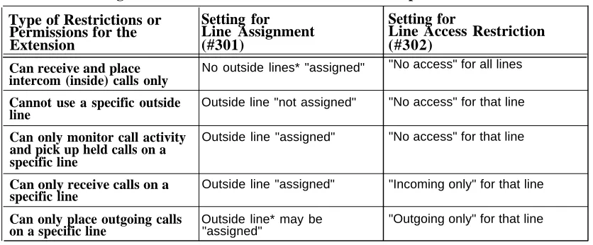
Tables 2-1 and 2-2 summarize the available dialing restrictions and permissions, showing how they can be combined in a variety of ways to customize an
extension's dialing privileges.
Table 2-1. Settings that Restrict an Extension's Access to a Specific Line
Type of Restrictions or
Setting for
Permissions for the
Line Assignment
Extension
(#301)
Can receive and place No outside lines* "assigned"
intercom (inside) calls only
Cannot use a specific outside Outside line "not assigned"
line
Can only monitor call activity Outside line "assigned"
and pick up held calls on a specific line
Can only receive calls on a Outside line "assigned"
specific line
Can only place outgoing calls Outside line* may be
on a specific line "assigned"
Setting for
Line Access Restriction
(#302)
"No access" for all lines
"No access" for that line
"No access" for that line
"Incoming only" for that line
"Outgoing only" for that line
Table 2-2. Settings that Restrict an Extension's Dialing Once It Gets an Outside Line
Type of
Setting for
Setting for
Setting for
Setting for
Restrictions or
Line
Line Access
Outgoing Call
Disallowed
Permissions for
Assignment
Restriction
Restriction
Phone Number
the Extension
(#301)
(#302)
(#401)
Lists (#404)
Can place Outside line* "No restriction" "Local only" Any local
intercom and may be numbers the
local calls only "assigned"
(and can answer
extension should
any call) not dial
Can place Outside line* "No restriction" "No restriction" Any local and
intercom, local may be long-distance
and long- "assigned" numbers the
distance calls (and can answer
extension should not dial
any call)
Setting Up Groups of Extensions
You can set up four types of extension groups:
■
■
■
■
Pickup Group Extensions (#501) assigns extensions to up to four
Pickup Groups. A Pickup Group lets any user in the system answer outside calls for any extension in that group.
Calling Group Extensions (#502) assigns extensions to up to four
Calling Groups. A Calling Group lets users ring or page all extensions in that group simultaneously.
Hunt Group Extensions (#505) assigns extensions to up to six Hunt
Groups. A Hunt Group lets users ring or voice signal the first available (non-busy) extension in that group. If an extension does not answer, the call tries each available extension in turn until the call is answered.
Night Service Group Extensions (#504) assigns extensions to the Night
Service Group. When Night Service is on, calls ring immediately at Night Service extensions (if the outside line the call comes in on is assigned to the extensions).
Setting Up Auxiliary Equipment
The following programming procedures help you manage auxiliary equipment. See Chapter 4 for more information on auxiliary equipment configurations or refer to the procedure name in Chapter 5 for details on programming and using the procedure:
■
■
■
■
■
■
Fax Machine Extensions (#601) lets you identify an extension on which
a fax machine is installed.
Music on Hold (#602) activates or deactivates the MUSIC ON HOLD jack
on the processor module.
Hotline (#603) allows you to identify Hotline extensions, so that when a
person lifts the handset of the Hotline phone, a predetermined extension automatically rings.
Doorphone Extensions (#604 and #605) identifies the extensions on
which doorphones are installed. Doorphone Alert Extensions (#606) identifies any number of extensions that ring when the button on a doorphone is pressed.
AA/VMS Extensions (#607) identifies extensions on which automated
attendants are installed. This lets the system notify users with display phones when they are receiving a call that has been transferred from the automated attendant. Also, use Transfer Return Extension (#306) to identify the extension to which a call transferred by the automated attendant should be routed if the destination extension does not answer.
SMDR Record Type (#608) specifies the type of calls that you want to
record for call reporting—either all calls or outgoing calls only. The
Account Code Entry feature lets users assign account codes that will be
System Speed Dialing
You can program frequently dialed phone numbers—such as suppliers, repair services, customers, or other business associates—so that all users in the
system can dial them by pressing three buttons: Feature (or # on a standard phone) plus a two-digit code.
NOTE:
Personal Speed Dial numbers can also be programmed for individual extensions.
Using System Programming
System Programming changes settings for the system as a whole, or for individual lines or extensions. You can also use System Programming to set up dialing restrictions, define groups, or set up auxiliary equipment. Refer to the filled-out System Planner when you are changing system settings, and be sure that any changes in programming are recorded there.
System Programming requires an MLS-34D, MLS-18D, or MLS-12D phone at extension 10 or extension 11, with a programming overlay placed over the phone's dial pad. System Programming procedures are identified by # and a three-digit code (for example, System Date is #101).
Programming Mode
To enter programming mode, you press Feature 0 0 , followed by
System Program System Program .
Once you are in programming mode, you can access a programming procedure in one of two ways:
■
■
Direct Method. With this method, you access a programming procedure
directly by dialing the code for that procedure. This method is best when you are using only a few procedures during a programming session and you know the codes.
Cycle Method. With this method, you cycle through the procedures in
numerical order.
Once you are in programming mode, you can also move between System Programming and Centralized Telephone Programming. To do so, press the right Intercom button to move to Centralized Telephone Programming and the left Intercom button to move back to System Programming.
To exit programming mode, you can either press Feature 0 0 or lift the handset off-hook, then place it back in the cradle.
NOTE:
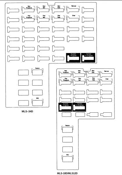
The Programming Overlays
System Programming requires a programming overlay placed over the dial pad of the MLS-34D, MLS-18D, or MLS-12D system phone. (Overlays are provided with the control unit. Replacements can be ordered through the AT&T
Sourcebook.) Figure 2-3 illustrates the programming overlays.
During System Programming, the normal functions of several buttons on the display phone at extension 10 or 11 change. For example, the left Intercom
button becomes System Program , the button used to enter programming mode. To identify these buttons while programming, place the appropriate
programming overlay provided with the system on the dial pad of the phone at extension 10 or 11.
You use the following special buttons while programming:
■
■
■
■
■
■ ■
■ ■
Next Procedure and Prev Procedure cycle forward and backward through the programming procedures. You can use these buttons to select a procedure.
Next Item and Prev Item cycle forward and backward through a procedure's parameters. A parameter is typically an outside line, an
extension, or a telephone list entry.
Next Data and Prev Data cycle forward and backward through the valid list entries. These buttons work only for fixed data, such as a line or extension number. They do not work for variable data such as date, time, password, telephone numbers, or doorphone assignments.
Remove returns the current setting to the factory setting—or when using
Line Assignment (##301), removes lines from an extension.
Enter ends an entry of variable length, such as a telephone number in an Allowed Phone Number List.
System Program starts the System Programming process.
Central Tel Program starts the Centralized Telephone Programming process (that is, customizing individual telephones centrally from extension 10 or
11).
Feature when followed by 0 0 , enters or exits programming mode.
MLS–34D
MLS-18D/MLS12D
Telephone Programming Options
System telephones are ready to use when they are installed, but they can be customized to meet the needs of your business and individual users. This customization is accomplished through Telephone Programming.
Automatic Line Selection
When a user lifts the handset of a telephone, the system chooses an idle line automatically. Automatic Line Selection sets the order in which the system looks for an idle line. You can set the system to look for outside lines first—in any desired order. For standard phones, or for any phone used mainly to call other extensions, select an inside (intercom) line first.
Line Ringing
Line Ringing defines when each outside line will ring at a phone. For each line
at an extension, you can specify "immediate ring," "delayed ring" (phone rings after a 20-second delay), or "no ring."
Personal Speed Dialing
Personal Speed Dial numbers are outside phone numbers that a user dials by pressing Feature (or # on a standard phone) plus a two-digit code. Unlike System Speed Dial numbers, which are available to all users in the system, Personal Speed Dial numbers are available only at the extension for which they are programmed.
Programming Telephone Buttons
Telephone buttons without lines assigned to them can be programmed to store
dial-code features—features such as Exclusive Hold or Conference Drop that
are accessed by a dial code—or telephone numbers, so you can use the feature or dial the phone number with one touch. Once programmed, these buttons are called Auto Dial buttons, because simply pressing the button automatically dials the feature code or the telephone number. "Auto Dialing" in Chapter 5 provides more information.
A user who has a system phone with programmable buttons should consider programming them with a combination of frequently used dial-code features and outside and intercom telephone numbers.
Programming a Receptionist's Extension
If you set up a centralized telephone answering position at extension 10, use the following settings to customize it:
■ Immediate call answering. If the receptionist should answer all calls,
assign all lines (Line Assignment #301) to extension 10. Set Line
■
■
Backup call answering. If the receptionist should answer some lines
only when a user does not pick up, set Line Ringing for those lines to
"delayed ring."
No answering. If some lines should not be picked up by the receptionist
at all, either set Line Ringing for those lines at the receptionist's extension to "no ring" or simply unassign (Line Assignment (#301)) those lines from the receptionist's extension. In either case, Line Access
Restriction (#302) should be set to "no access" to prevent the
receptionist from using the Direct Line Pickup code.
See "Line Assignment" and "Line Ringing" in Chapter 5 for specific instructions on programming these settings for call coverage.
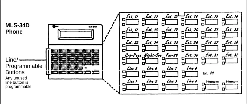
If you do not have an MLS-CA24 Intercom Autodialer on extension 10, you can program the unused buttons on the MLS-34D phone with Intercom Auto Dial numbers for the extensions you dial most frequently. To illustrate, the MLS-34D phone shown in Figure 2-4 has Intercom Auto Dial buttons for extensions 11 through 32, starting with the top left programmable button. Dial-code features are programmed on three other unused buttons (just above lines 5–7).
MLS-34D Phone
Line/
Programmable Buttons
Any unused line button is programmable
Figure 2-4. Button Programming for Receptionist's Phone
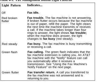
The lights of an Intercom Auto Dial button show the status of the extension, so the receptionist can tell whether the phone at the extension is idle (no lights), busy (red on), calling the receptionist (green flash), or ringing back after the receptionist transferred a call (green flutter). If a fax extension is programmed as an Auto Dial button, the button also shows when the fax machine at the extension is not responding (for example, when it is out of paper). (For more information, see "Lights" in Chapter 3).
In summary, Intercom Auto Dial buttons give the receptionist the ability to dial or transfer calls to extensions with one touch and to see their status. (The
technical names of these features are Direct Station Select [DSS] and Busy
Using a Second Programming Extension
You may want to connect an MLS-34D, MLS-18D, or MLS-12D telephone to extension 11 for system and telephone programming. Using a second
programming extension gives you the ability to program without disrupting call handling by the receptionist on extension 10.
Using Telephone Programming
There are two ways to program a telephone: Centralzed Telephone
Programming from extension 10 or 11 (see below), and Extension Programming
from a user's own extension (see page 2-18).
Telephone Models
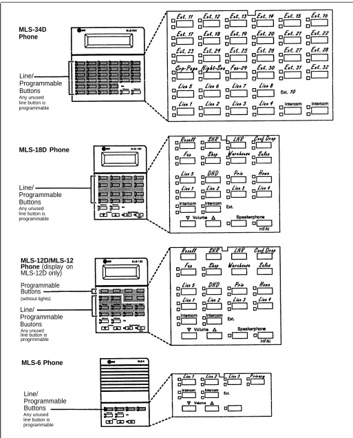
Figure 2-5 illustrates these system phones: MLS-34D, MLS-18D, MLS-12D/ MLS-12, and MLS-6. As you program buttons, mark their functions on the phone's labeling sheet (see the examples in Figure 2-5).
NOTE:
An MLS-6 phone with 4 lines assigned to it has no programmable buttons. The MLC-6 cordless phone looks just like an MLS-6 phone when you program it centrally.
Using Centralized Telephone Programming
Use Centralized Telephone Programming to program features or store telephone numbers for individual extensions from extension 10 or 11.
Automatic Line Selection and Line Ringing must be programmed using
Centralized Telephone Programming; all other features can be programmed on a system phone at the user's extension. If a user has a standard phone, Personal Speed Dial numbers for the extension can be programmed only by using Centralized Telephone Programming.
During Centralized Telephone Programming, the display phone at extension 10 or 11 takes on the characteristics of the telephone being programmed, including any System Programming settings and the lines assigned to the phone. Make sure the programming phone is as large as the largest phone in the system, because an MLS-18D phone cannot program an MLS-34D phone and an MLS-12D cannot program an MLS-18D. When you enter Centralized Telephone Programming, green lights appear next to any line buttons that are already assigned.
To program a phone from extension 10 or 11, use the following procedure:
1. Place the Programming Overlay over the dial pad of the system display phone at extension 10 or 11—see "The Programming Overlays" earlier in this
chapter for more information.
MLS-34D Phone
Line/
Programmable Buttons
Any unused line button is programmable
MLS-18D Phone
Line/
Programmable Buttons
Any unused line button is programmable
MLS-12D/MLS-12 Phone (display on
MLS-12D only) Programmable Buttons
(wihtout lights)
Line/
Programmable Buutons
Any unused line button is progrmmable
MLS-6 Phone
Line/
Programmable Buttons
Any unused line button is programmable
3.
4.
5. 6.
7.
Dial the extension number to be programmed.
Buttons on which lines are assigned for the extension light up to show the current Line Ringing settings. Remaining buttons can be programmed with Auto Dial numbers or features.
At this point, you can:
■
■
■
Use Automatic Line Selection (see Chapter 5) to change the order in which the telephone tries to select a line when the user picks up the handset. (You must change Automatic Line Selection for an extension immediately after you enter programming mode and select the extension.)
Use Line Ringing (see Chapter 5) to change the ringing for an individual line.
Program Personal Speed Dial Numbers or Auto Dial numbers or features (see Chapter 5).
To program another button, press the new button, then dial the feature code. To change the settings for another extension, press Central Tel Program , then dial the new extension number.
To erase a button feature, press the button and then press Mic .
To end programming:
■ Dial Feature 0 0 , or
■ Lift the handset off-hook, then place it back in the cradle.
Using Extension Programming
From their own phones, users can program features or store telephone numbers on buttons using Extension Programming. Automatic Line Selection and Line
Ringing must be programmed using Centralized Telephone Programming; all
other features can be programmed using a system phone at the user's
extension. If the user has a standard phone, Personal Speed Dial numbers for the extension must be programmed using Centralized Telephone Programming. To program at the extension, use the following procedure:
1.
2.
3.
4.
To start programming, dial Feature 0 0 .
Buttons on which lines are assigned for the extension light up to show the current Line Ringing settings. Remaining buttons can be programmed with Auto Dial numbers or features.
To change the programming for a button, press the button, then dial the code for the feature.
You can also program Personal Speed Dial numbers for the extension. To program another button, press the new button, then dial the feature code. To erase a button feature, press the button and then press Mic .
Learning About Telephones
3
Contents
System Telephones
■ Buttons and Indicators■ Lights
■ Ringing Patterns
■ Dial Tones
■ Using the Handset, Speaker, and Microphone Hands-Free Answer on Intercom (HFAI) Speakerphone Performance Tips
Standard Telephones
■ Ringing Patterns■ Dial Tones
■ Using the Switchhook
■ Limitations
■ Feature Phones
Combination Extensions
3-1 3-2 3-4 3-5 3-5 3-5 3-6 3-6 3-7 3-8 3-8 3-8 3-8 3-9 3-10
Using Telephones
3-11■ Basic Call Handling Features 3-11
Learning About Telephones
3
System Telephones
Buttons and Indicators
MLS-34D
Display
Line/Programmable Buttons (32 with lights)
Intercom Buttons (2)
MLS-18D
Display (not on MLS-12) Programmable Buttons (6 without lights)Line/Programmable Buttons
Intercon Butons (2)
MLS-12D/MLS12
The following buttons and displays appear on system phones. (Some controls and indicators are not available on all phones.) Display. (MLS-34D, MLS-18D, and MLS-12D only) Shows date, day, and time when phone is idle, number dialed when placing a call, extension number calling when receiving an intercom call, extension number dialed when transferring a call, and duration while a call is in progress. When programming, shows settings, options, and prompts. To adjust the MLS-18D display contrast, see Volume Control Buttons.
Line/Programmable Buttons. Used for outside lines or (if no line is assigned on a button) for programming telephone or extension numbers, or other dialing sequences (such as dial-code features). When a line is assigned, you can press the line button to make a call on a specific line (lights show status of line), When no line is assigned, the button may be programmed. The MLS-34D has 32 line/programmable buttons; the MLS-18D has 16 programmable line/buttons; the MLS-12D and MLS-12
have 10 line/programmable buttons; the MLS-6 and MLC-6 phones have 4 line/programmable buttons. Intercom Buttons. Press either button to place an intercom (inside) call to another extension.
Other Buttons and Indicators (shown in exploded views)
Feature. Press to change programmed settings or use dial-code features. Conf (Conference). Press to add other parties to your call.
MLS-6
Line/Programmable Butons (4)
Intercom Butons (2)
MLC-6
Earpiece Volume Control
Line/Programmable Buttons
Intercom Buttons
Spkr (Speaker) (all models except the MLC-6). Press to talk without lifting the handset. Turns on speaker and microphone (if available), so you can dial or have a conversation without lifting the handset.
Mic (Microphone) (MLS-34D, MLS-18D, MLS-12D, and MLS-12 only). Leave on to use Hands-Free Answer on Intercom (HFAI) feature. The light next to this button shows when the microphone is turned on; press this button to turn off the microphone when you are using the built-in speaker.
Message Indicator. Lights when someone signals you with the Message Light On feature.
Volume Control Buttons. Press ▼ to decrease or ▲ to increase the volume of the ringer, speaker, and handset:
■ To adjust ringer volume, press ▼ or ▲ while the phone is idle and the handset is on the phone. ■ To adjust speaker volume, press ▼ or ▲ while listening to a call through the speaker.
■ To adjust handset volume, press ▼ or ▲ while listening through the handset.
TO adjust the display contrast on the MLS-18D phone, press ★ and then ▼ to decrease the brightness or ▲ to increase the brightness,
while the phone is idle and the handset is on the phone.
Lights
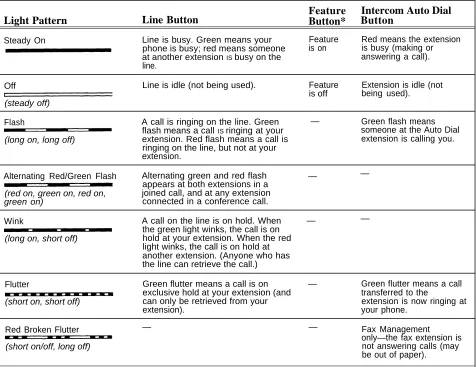
Each line button has a green light and a red light. The meaning of these lights varies, depending on whether a button is used to access an outside line, is programmed with a dial-code feature, or is programmed with an Intercom Auto Dial number. (Auto Dial buttons for fax extensions show additional information; these "Fax Management" buttons are described in Chapter 4.)
Table 3-1 shows the meanings of the various light patterns for each possible button assignment.
Table 3-1. Light Patterns for System Phones
Feature
Intercom Auto Dial
Light Pattern
Line Button
Button*
Button
Steady On Line is busy. Green means your Feature Red means the extension
phone is busy; red means someone is on is busy (making or at another extension IS busy on the answering a call).
line.
Off Line is idle (not being used). Feature Extension is idle (not
is off being used).
(steady off)
Flash A call is ringing on the line. Green — Green flash means
flash means a call IS ringing at your (long on, long off)
someone at the Auto Dial extension. Red flash means a call is extension is calling you. ringing on the line, but not at your
extension.
Alternating Red/Green Flash Alternating green and red flash — —
appears at both extensions in a (red on, green on, red on, joined call, and at any extension green on) connected in a conference call.
Wink A call on the line is on hold. When — —
the green light winks, the call is on (long on, short off) hold at your extension. When the red
light winks, the call is on hold at another extension. (Anyone who has the line can retrieve the call.)
Flutter Green flutter means a call is on — Green flutter means a call
exclusive hold at your extension (and transferred to the
(short on, short off) can only be retrieved from your extension is now ringing at
extension). your phone.
Red Broken Flutter — — Fax Management
(short on/off, long off)
only—the fax extension is not answering calls (may be out of paper).
Ringing Patterns
You can tell what kind of call you are receiving by the way your telephone rings.
■ A single ring (ring . . . ring . . . ring . . .) means that you are receiving an
outside call.
■ A ring and a beep (ring BEEP . . . ring BEEP . . . ring BEEP . . .) means
that someone is calling you from another extension. If you have a system phone with a display, the caller's extension number will show on the display.
■ A ring and two beeps (ring BEEP BEEP . . . ring BEEP BEEP . . . ring
BEEP BEEP . . .) means either that a transferred call is coming in, or that a
transferred call that was not answered is ringing back.
NOTE:
If you use the system with PBX or Centrex lines, the PBX/Centrex ringing patterns are not passed to phones. Phones use the ringing patterns described here instead.
Dial Tones
You will encounter two different dial tones when calling with a system phone:
■
■
Outside dial tone is generated by your local phone company to indicate
that you are connected with an outside line.
Intercom dial tone is generated by the system to indicate that you are
connected with an inside line. You hear this dial tone when you are making an inside, or intercom, call.
To hear the difference between the two types of dial tones on a system phone, press a line button. The dial tone you hear is an outside dial tone. To hear an intercom dial tone, press Intercom .
Using the Handset, Speaker, and Microphone
Every MLS-model telephone has a speaker, which you can turn on by pressing
Spkr . When the green light next to Spkr is on, the speaker is on.
MLS-34D, MLS-18D, MLS-12D, and MLS-12 phones also have a microphone. On these phones, pressing Spkr turns on both the speaker and the
microphone. In addition, you can turn just the microphone on and off by pressing Mic . When the green light next to Mic is on, the microphone is on. If you prefer to dial and conduct calls without lifting the handset, you can use the speaker and the microphone instead. Use these techniques to make calls with the speaker and the microphone (if you have one):
■
■
■
To turn off the microphone when you are using the speaker, press Mic .
This will mute your voice so the other party cannot hear you. If you are already on a call, you can switch from the handset to the speaker and microphone (on an MLS-34D, MLS-18D, MLS-12D, or MLS-12 phone) by pressing Spkr and hanging up the handset. Conversely, if you are using the speaker and microphone and want to switch to the handset, lift the handset and the speaker and microphone will turn off.
Use the Hands-Free Answer on Intercom (HFAI) feature to answer
voice-signaled calls without lifting the handset (see below).
Hands-Free Answer on Intercom (HFAI)
When you receive a voice-signaled intercom call, your phone beeps to indicate that your speaker has been turned on automatically, and you hear the caller's voice over your phone's speaker. If you leave the microphone on your phone on all the time, you can simply start talking when you hear the caller, without lifting the handset. This feature is called Hands-Free Answer on Intercom.
NOTE:
Since MLS-6 phones do not have microphones, you must lift the handset to answer voice-signaled calls to those phones.
Any user in the system can make a voice-signaled call to a system telephone by pressing ✳ and then dialing an extension number. (You can make a
voice-signaled call from either a system phone or a standard phone. However, if you try to make a voice-signaled call to a standard phone or MLC-6 cordless phone, it will ring.)
NOTES:
1. The HFAI feature can only be turned on or off when your phone is idle. Muting your voice while you are on a call only turns off the microphone for the duration of the call.
2. If HFAI is on and you are already on a call, you will not hear any other voice signals to your extension.
Speakerphone Performance Tips
The speaker on your MLS-34D, MLS-18D, MLS-12D, or MLS-12 telephone has a sensitive sound-activated switch. Room acoustics and background noise can affect the proper operation of the speakerphone. To ensure that your
speakerphone works effectively, follow these guidelines:
■ Avoid placing your phone in areas with high background noise caused by loud voices, radios, printers, copiers, typewriters, other noisy office equipment, and heater and air conditioning fans.
■
■
■ ■ ■
■
Avoid talking before the other person is finished speaking. When you both talk at the same time, only one person's voice comes through. Do not use your speaker to make announcements over a loudspeaker paging system connected to your phone system.
When talking, always face your phone and stay within two feet of it. Place your phone at least six inches away from the edge of your desk. If you have difficulty hearing the other party, increase the speaker volume. If the difficulty persists, lift your handset to continue the conversation.
In conference rooms, a separate speakerphone (such as the AT&T S203 Speakerphone) is recommended, since the built-in speaker on a system phone is designed for individual use.
Standard Telephones
In addition to system phones, you can connect industry-standard touch-tone or rotary dial telephones—and even some feature phones (which have built-in calling features)—directly to the system. You can also combine standard phones on the same extension with system phones or other devices, without using expensive adapters or connectors.
Standard telephones can do many of the things that system telephones can do, and you can save money by using them in certain situations when a system telephone is not needed. Follow these guidelines when using standard phones:
■
■
■
■
Use standard phones as power failure backups. In the event of a power failure, standard phones at extensions 10, 16, 22, and 28 connect to lines 1, 3, 5, and 7, respectively, for continued operation; but system phones will not work. You can connect standard phones in combination with system phones at power failure extensions, or you can simply keep spare standard phones at those extensions to serve as replacements in case of a power failure.
To use a dial-code feature, press # (in place of Feature used on system phones) followed by its dial code when you hear intercom dial tone. For dial-code features that use Intercom on system phones, dial only the two-digit code. (Instructions for using these features on standard phones are included in Chapter 5, "Feature Reference.")
To use a Speed Dial number, press # followed by its two-digit code when you hear intercom dial tone. (For details, see "System Speed Dialing" in Chapter 5.)
Ringing Patterns
Standard phones have these ringing patterns:
■ ■ ■
An outside call will ring . . . ring . . . ring.
An intercom call will ring-ring . . . ring-ring . . . ring-ring. A transferred call, or a call on hold that is ringing back, will
ring-ring-ring . . . ring-ring-ring . . . ring-ring-ring.
NOTE:
If you use the system with PBX or Centrex lines, the PBX/Centrex ringing patterns are not passed to telephones. Telephones use the ringing patterns described here instead.
Dial Tones
Standard phones have two different dial tones:
■
■
Outside dial tone is generated by your local telephone company to
indicate that you are connected with an outside line.
Intercom dial tone is generated by the system to indicate that you are
connected with an inside line. You hear this dial tone when you are making an inside, or intercom, call.
To hear the difference between the two dial tones, lift the handset. The dial tone you hear (assuming the phone is set to select intercom first, as recommended in this guide) is an intercom dial tone. To hear an outside dial tone, press 9 .
Using the Switchhook
Some of the call handling instructions in this guide direct you to "rapidly press and release the switchhook." Pressing the switchhook for 1/4 to 1 second sends