Design and Optimization of Multiple Slots
Microstrip Patch Antenna for Wireless Applications
Arun1, Mrs. Ankita Mittal2,
1
Student (M.Tech, ECE), 2Assistant Prof.
Galaxy Global Group Of Institutions, Ambala Kurukshetra University, Kurukshetra, Haryana, India.
Abstract: Multiband Wang-shaped fractal antenna is obtained by applying fractal geometry .Initially a rectangular patch is taken and fractal geometry is applied. Two iterations of fractal geometry are applied to form double wang-shaped fractal, 4.6 GHz, 5 GHz and 7.6 GHz with return loss of -20.75 dB, -18.3 dB, -21.1 dB and -27.3 dB, gain of 0.7 dBi, 2.36 dBi, 4.13 dBi and 2.63 dBi and bandwidth of 200 MHz, 300 MHz and 900 MHz at 3.7 GHz, 4.6 GHz, 5 GHz and 7.7 GHz. This antenna found applications for C band and X band applications.
Keywords: Fractal antenna, Multiband, Microstrip patch antenna, DGS, E wang shape.
I.INTRODUCTION
An antenna can be defined as, “a usually metallic device for radiating or receiving radio waves”. The IEEE standard definition of antenna is defined as, “a means for radiating or
receiving radio waves.” The antenna is a structure between free space and a device. The guiding device or one can say transmission line may take the form of a coaxial line or a hollow pipe i.e. also called waveguide, and it helps in transporting electromagnetic energy from the transmitting source to antenna or from antenna to receiver. These antennas are important
component of communication systems. “An antenna is a device
used to transform an RF signal, travelling on a conductor, into
an electromagnetic wave in free space”. Antennas tells the
property which is known as reciprocity, that means an antenna will maintain the same characteristics regardless of that if it is transmitting or receiving. Antennas are mostly resonant devices, which operate efficiently in narrow frequency band. An antenna has been tuned to the same frequency band of the radio system to which it is connected; otherwise the reception and the transmission will be impaired. Microstrip antennas were very
popular in 1970’s primarily for space borne applications. They
were used for government and commercial purpose applications. The antennas consist of a metallic patch on a ground substrate.
The metallic patch can be of different configurations that can be rectangular and circular patches as shown in figure1.1 and are the most popular because they are easily analyzed and fabricated and their attractive radiation characteristics, especially for low cross polarization radiation. These microstrip antennas are of low profile, conformable to planar structures and non planar surfaces, also simple and inexpensive to fabricate using modern printed-circuit technology, mechanically robust when they are mounted on rigid surface, also compatible with MMIC design, and resonant frequency, polarization, high performance aircraft, missiles, cars, spacecraft, satellites and even handheld mobile telephones hence are very versatile in these.
II.DESIGN AND IMPLEMENTATION
divided into 5 parts on both sides and in centre so that each one represent E-shape antenna and when seen together, antenna can be thought of combination of two wang shape antenna
Table 1:Dimensions of Double Wang shaped Fractal Patch Antenna
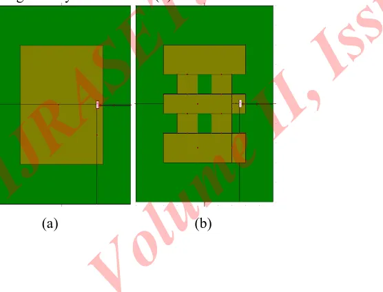
In order to obtain first iteration of fractal geometry, first of all entire length of 30 m is taken. Fractal geometry has been applied on length of 25 mm leaving 2.5 mm top and bottom unchanged. 25 mm of length is divided into 5 parts and two squares with dimension of 5 mm are removed from sides and centre leaving double wang shape structure. This structure is thought of four E-shapes. This antenna designed is special; case of slot antenna. The geometry is shown in 1(b).
(a) (b)
[image:3.612.24.302.475.687.2](c)
Figure 1: Double Wang-Shaped FMPA (a) 0thIteration (b) 1st Iteration and (c) 2ndIteration
Second iteration of fractal geometry is obtained by applying Minkowski fractal geometry algorithm on both sides. Second iteration is obtained by cutting slots of square of 1mm. In this way scale factor of one fifth is obtained. Each square of 5 mm is taken and is divided into 5 equal parts of 1mm each leaving two squares cut to form wang shaped structure. Hence self-similar characteristics are obtained. Here this antenna is combination of four fractal shape geometry structure to form double wang shape fractal as shown in figure 1(c). Whenever DGS is applied to antenna, characteristics of antenna improve. There are three different DGS have been applied to antenna in order to analyze characteristics. Three DGS which are applied to know behaviour of antenna are plus shape DGS, Dumbbell shape DGS and square cut shape DGS. This geometry shows top view and bottom view of dumbbell shape DGS as shown in figure 2(a) and 2(b). These numbers of cuts can be increased or decreased to analyze antenna characteristics. But by removing large number of cuts, antenna efficiency decreases. There are a number of DGS Techniques that can be applied, Parametric analysis of antenna can be applied in terms of antenna dimensions like patch dimension, ground dimension, variation of feed point and thickness of substrate.
Variable Value
Length of patch 30 mm
Width of patch 30 mm
Length of ground 50 mm
Width of ground 50 mm
Thickness of substrate 2.4 mm
Feeding technique used Coaxial Feeding Technique
Substrate used FR-4
Dielectric constant 4.4
Loss Tangent 0.02
Feed point (13, 0, 0)
First iteration cut 5X5 mm2
(a)
(b)
Figure 2: Double Wang-Shaped FMPA with DGS (a) Top View
(b) Rear View
There are different DGS that can be applied but out of all configurations, antenna that has been designed using this DGS configuration gives best result. It was found by applying different iterations of fractal geometry, better results may obtain but to obtain better characteristics of antenna like good bandwidth one may need DGS. DGS plays an important role in improving bandwidth of microstrip antenna. DGS is called as defected ground structure. DGS is made by cutting a shape on ground plane. Depending on shape of defect, current in ground plane gets distributed.
III.RESULTS AND DISCUSSIONS
[image:4.612.24.583.123.650.2]Double wang-shaped structure as shown in figure 1(c) is obtained by applying two iterations on fractal geometry on square patch having rectangular slot. Slots have been cut on both sides of antenna and also in middle to obtain structure as shown in figure 3. Return loss versus frequency for different iterations are shown in figure 3. From these characteristics, it is found that characteristics of antenna improve by increasing number of iterations.
Figure 3: Return Loss Vs. Frequency for Different Fractal Iterations of Double Wang-shaped FMPA
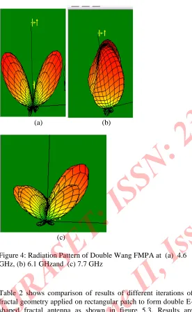
7.7 GHz. Radiation pattern of antenna at different frequencies namely 4.6 GHz, 6.1 GHz and 7.7 GHz has been shown in figure 4 (a), 4(b) and 4(c).
(a) (b)
[image:5.612.208.573.118.600.2](c)
Figure 4: Radiation Pattern of Double Wang FMPA at (a) 4.6 GHz, (b) 6.1 GHzand (c) 7.7 GHz
Table 2 shows comparison of results of different iterations of fractal geometry applied on rectangular patch to form double E-shaped fractal antenna as shown in figure 5.3. Results are analyzed in terms of antenna parameters.
Table 2: Comparison Results of Different Iterations
IV.EFFECT OF APPLYING DGS
Parametric analysis has been carried out to obtain best antenna configuration that has best results. Antenna has been fed by coaxial fed and feed point is adjusted such that impedance matching takes place. There are different DGs that can be applied but in order to analyze effect of applying DGS, one may compare characteristics of antenna with DGS and without DGS. Plus shaped DGS has been applied to ground plane of antenna. Feed to antenna is given as coaxial feed. By applying DGS, it is found that characteristics of antenna improves a lot. Return loss vs. frequency comparison for antenna with or without DGS is made as shown in figure 5.
Figure 5: Return Loss vs. Frequency for Antenna with DGS
Results are analyzed in terms of return loss, gain, directivity and bandwidth. By applying DGS to antenna, characteristics of antenna improved in terms of return loss, gain and bandwidth. This antenna resonates at 3.7 GHz, 4.6 GHz, 5 GHz and 7.6
Iteration Number
Resonance Frequency
(GHz)
Return Loss (dB)
Gain (dBi)
Direct ivity (dBi)
Band width (MHz)
0th Iteration
4.6 -15.35 1.73 5.9 225
6.8 -12.45 4.40 10.6 195
Initiator by cutting slot
4.6 -11.20 3.23 7.86 90
6.3 -12.35 6.50 10.70 270
7.6 -13.65 1.64 7.18 210
2nd 4.6 -13.35 3.28 7.8 135
6.1 -15.67 2.13 8.4 240
[image:5.612.18.294.155.603.2]GHz with return loss of -20.75 dB, -18.3 dB, -21.1 dB and -27.3 dB, gain of 0.7 dBi, 2.36 dBi, 4.13 dBi and 2.63 dBi and bandwidth of 200 MHz, 300 MHz and 900 MHz at 3.7 GHz, 4.6 GHz, 5 GHz and 7.7 GHz. It is find that bandwidth of antenna improves by applying DGS. Without application of DGS, This antenna resonated at three bands namely 4.6 GHz, 6.7 GHz and 8.6 GHz with good characteristics. This antenna has return loss of -13.35 dB, -15.62 dB and -20.9 dB, gain of 3.28 dBi, 2.13 dBi and 3.53 dBi at corresponding frequencies. This antenna has return loss less but bandwidth needs to be improved as this antenna has bandwidth of 135 MHz, 240 MHz and 450 MHz at 4.6 GHz, 6.1 GHz and 7.7 GHz. Hence one may get idea of result change take place by applying DGS.
Table 3: Antenna Characteristics by applying DGS
Iterat ion Num ber Resonance Frequency (GHz) Retur n Loss (dB) Ga in (d Bi ) Directi vity (dBi) Bandwi dth (MHz)
2nd 4.6
-13.35 3.2 8 7.8 135 6.1 -15.67 2.1 3 8.4 240 7.7 -20.85 3.5 3 6.7 450 Main DGS 3.7 -20.75
0.7 6.8 130
4.6 -18.3 2.3
6
7.56 200
5 -21.1 4.1
3
8.5 300
7.6 -27.3 2.6
3
7.77 900
It is find that bandwidth of antenna improves by applying DGS. Radiation pattern corresponding to 3.7 GHz, 4.6 GHz, 5 GHz and 7.6 GHz has been shown in figure 6(a), 6(b), 6(c) and 6(d).
(a)
(b)
(c)
Figure 6: Radiation Pattern of FMPA at (a) 3.7 GHz, (b) 4.6
GHz, (c) 5GHz and (d) 7.6 GHz
REFERENCES
[1]
Varadhan C. Pakkathillam J. Kizhekke, Kanagasabai M.,Sivasamy R., Natarajan R. and Palaniswamy S. Kumar.
“Triband Antenna structures for RFID Systems Deploying Fractal Geometry”, “IEEE Letters on Antennas and Wireless Propagation”, Vol. 12, pp 437-440, 2013.
[2]
Janani. A., Priya. A. “Design of E-Shape Fractal Simple Multiband Patch Antenna for S-Band LTE and VariousMobile Standards”, “International Journal of Engineering and Science”,Vol. 3, Issue 1, pp 12-19, 2013.
[3]
Ojaroudi M., Ojaroudi, N., Ghadimi, N. “Dual Band-Notched Small Monopole Antenna with Novel Coupled Inverted U-Ring Strip and Novel Fork-Shaped Slit for
UWB Applications”, “IEEE Antennas and Wireless Propagation Letters”, Vol. 12, pp. 182-185, 2013.
[4]
Behera S. and Vinoy K. J. “Multi-Port Network Approachfor the Analysis of Dual Band Fractal Microstrip
Antennas”, “IEEE Transactions on Antennas and Propagation”, Vol. 60, No. 11, pp 5100-5106, 2012.
[5]
Ram V., Anjaria V., Boriya P. and Patel N. “Design and Development of Switchable Fractal Patch Antenna for GPSApplication”, “International Journal of Engineering and Science”, Vol. 1, Issue. 7, pp 46-50, 2012.
[6]
Agarwal Vivek Kumar, Shaw Anand Kumar, DasMrinmoy. Kr, Mukherjee Jayati, Mandal Kaushik,. “A
Novel Compact Dual Frequency Microstrip Antenna”, “Sci
Verse Science Direct Procedia Technology”, Vol.4, pp 427-430, 2012.
[7]
Dalsania Piyush, Shah Brijesh, and Dwivedi Vyas DwivediVed Vyas. “Analysis of Multiband Behaviour on Square
Patch Fractal Antenna”, “Proceedings of IEEE International Conference on Communication Systems and Network Technologies (CSNT)”, Rajkot, India, pp. 76-78, 2012.
[8]
Chaimool. S, Chokchai. C, and Akkara ekthalin. P.“Multiband Loaded Fractal Loop Monopole Antenna for USB Dongle Applications”, “IEEE Electronics Letters”,
Vol. 48 and Issue: 23, pp 1446-1447, 2012.
[9]
Naser-Moghadasi M., Sadeghzadeh R. A., Fakheri, M. andAribi T. “Miniature Hook-Shaped Multiband Antenna for
Mobile Applications”, “IEEE Letters on Antennas and Wireless Propagation”,Vol.11, pp. 1096-1099,
2012.
[10]
Hasan M. N., Shah S. W., Babar M. I. and Sabir Z.“Designand Simulation based Studies of a Dual Band U-slot Patch