Technology (IJRASET)
LTE Techniques in 4G Wireless System Using
Protocol Stack
E. Thirumalai Nambi1, M. Rajeev Kumar2 1
Student, M.Tech (Network Engineering), 2Asst. Prof. / IT Vel Tech University, Chennai, Tamil Nadu, India
Abstract: LTE, an acronym for Long-Term Evolution. 4G LTE is a standard for wireless broadband technology designed to support roaming Internet access via cell phones and handheld devices. Due to the requirements on high data rate and low latency for broadband wireless communication systems, LTE air-interface protocol stacks to be designed and implemented with high data processing efficiency. LTE user equipment (UE), this paper analyzes the main challenges in the link-layer protocol stack design and application, including the data handling efficiency, synchronic, flexibility and portability. Authentication service is one of the most essential services in LTE networks. A memory access optimization and light-weighted thread model are proposed to improve the data processing efficiency. QoS Proposal to overcome such as channel capacity, latency, delay, Jitter, Packet loss, large RTTs. Voice over LTE is a methodology and group of technologies for the delivery of voice communications and multimedia sessions over Internet Protocol (IP) networks, such as the Internet. VoIP support the necessary protocols and features required for VoIP streaming including the implementation of Real Time Protocol (RTP) and an IP stack. In this paper, we survey and compare LTE security for Mobile Access Border security (RAN-to-EPC/S1), Internet Border security (EPC-to-Internet/SGi) and Partner Border security (EPC-to-EPC / S8).
Keyword: LTE protocol stack layer, User plane, Control plane, SGi, EPC.
I. INTRODUCTION
In contrast to the circuit-switched model of previous cellular systems, Long Term Evolution (LTE) has been designed to support only packet-switched services. It is based on the GSM/EDGE and UMTS/HSPA network technology, increasing the size and speed using a different radio interface together with core network improvements. It aims to provide seamless Internet Protocol (IP) connectivity between user equipment (UE) and the packet data network (PDN), without any disruption to the end users’ applications during mobility. While the term “LTE” encompasses the evolution of the Universal Mobile Telecommunications System (UMTS) radio access through the Evolved UTRAN (E-UTRAN), it is accompanied by an evolution of the non-radio aspects under the term “System Architecture Evolution” (SAE), which encloses the Evolved Packet Core (EPC) network. Composed LTE and SAE comprise the Evolved Packet System (EPS). EPS uses the concept of EPS bearers to route IP traffic from a gateway in the PDN to the UE. A bearer is an IP packet stream with a defined quality of service (QoS) between the gateway and the UE. The E-UTRAN and EPC together setup and release bearers as required by applications. This paper provides a comprehensive of the overall EPS network architecture, giving an impression of the functions provided by the core network (CN) and E-UTRAN. The protocol suite across the different edges is explained, along with an impression of the functions provided by the different protocol layers. The end-to-end bearer route along with QoS aspects are also conversed, including a typical procedure for launching a bearer. The remainder of this paper presents the network interfaces in detail, with particular focus on the E-UTRAN edges and the procedures used across these interfaces, including those for the provision of user mobility.
II. LTE-NETWORK ARCHITECTURE
Technology (IJRASET)
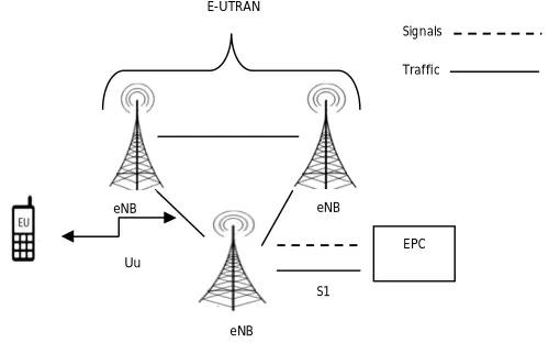
[image:3.612.220.419.95.167.2]Figure 1. LTE Network Architecture
A. User Equipment (UE)
The internal architecture of the user equipment for LT E is identical to the one used by UMT S and GSM which is actually a Mobile Equipment (ME). The mobile equipment comprised of the following important modules:
Mobile Termination (MT): This handles all the communication functions. Terminal Equipment (TE): This terminates the data streams.
Universal Integrated Circuit Card (UICC): T his is also known as the SIM card for LTE equipments. It runs an application known as the Universal Subscriber Identity Module (USIM). A USIM stores user-specific data very similar to 3G SIM card. T his keeps information about the user's phone number, home network identity and security keys etc.
B. E-UTRAN (The access network)
The E-UT RAN handles the radio communications between the mobile and the evolved packet core and just has one element, the evolved base station, called eNodeB or eNB. Each eNB is a base station that controls the mobiles in one or more cells. The base station that is communicated with a mobile is known as its serving eNB [2]. LTE Mobile communicates with just one base station and one cell at a time and there are following two main functions supported by eNB. The eNB sends and receives radio transmissions to all the mobiles using the analogue and dig ital signal processing functions of the LTE air interface [1]. The eNB controls the low-level process of all its mobiles, by sending them signalling communication such as handover commands.
Figure 2.E-UTRAN Access Network
Each eBN connect with the EPC by means of the S1 interface and it can also be connected to nearby base stations by the X2 interface, which is mainly used for signalling and packet forwarding during handover. A homeeNB (HeNB) is a base station that has been purchased by a user to provide femtocell coverage e within the home. A home eNB belongs to closed subscriber g group (CSG) and can only be accessed by mobiles with a USIM that also belong s to the closed subscriber group.
E-UTRAN
Uu S1
EPC
SGi Serve rs PDNs
Signals
Traffic Uu Signals
Traffic
eNB
EPC
eNB eNB
S1 E-UTRAN
Signals
Traffic
[image:3.612.198.453.403.564.2]Technology (IJRASET)
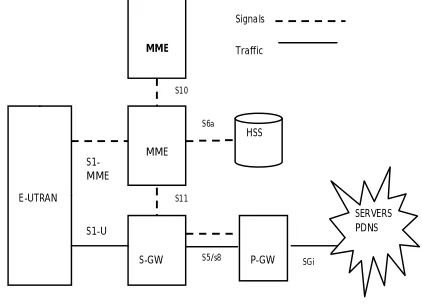
Below is a brief picture of each of the components shown in the above architecture?Figure 3. EPC Core Network
The Home Subscriber Server (HSS) component has been carried forward from UMT S and GSM and is a central database that contains information about all the network operator's subscribers [4]. The Packet Data Network (PDN) Gateway (P-GW) communicates with the outside world. Packet data networks PDN, using SGi interface. Each packet records network is identified by an access point name (APN). The PDN gateway has the same role as the GPRS support node (GGSN) and the serving GPRS support node (SGSN) with UMT S and GSM. The serving gateway (S-GW) act as a router, and to the fore data between the base station and the PDN gateway. The mobility management entity (MME) controls the high-level operation of the mobile by means of signalling messages and Home Subscriber Server (HSS). The Policy Control and Charging Rules Function (PCRF) is a component which is not shown in the above diagram but it is responsible for policy control executive, as well as for controlling the flow-based charging functionalities in the Policy Control Enforcement Function (PCEF), which resides in the P-GW. The interface between the serving and PDN gateways is known as S5/S8. This has two a little different implementation, to be exact S5 if the two devices are in the same network and S8 if they are in altered networks
III. LTE-PROTOCOL STACK LAYERS
The protocol stack is an implementation of a computer networking protocol stack. The terms are often used interchangeably. Severely speaking, the suite is the definition of the protocol, and the stack is the software execution of them. Individual protocols within a stack are often designed with a single function in mind. This modularization makes design and estimation easier. since each protocol module usually communicate with two others, they are commonly imaginary as layers in a stack of protocols. The lowest protocol always deals with "low-level", physical interaction of the hardware. Each higher layer adds more features. User applications generally deal only with the top most layers.
E-UTRAN
MME
MME
S-GW
HSS
P-GW
SERVERS PDNS
S1-MME
S5/s8
S1-U
S6a S10
S11
SGi
Signals
Technology (IJRASET)
Figure 4. LTE-Protocol Stack Layer
A. Physical Layer (Layer 1)
Physical Layer carries all information from the MAC transport channels over the air interface. Takes care of the link adaptation (AMC), power control, cell search (for initial synchronization and handover purposes) and other measurements (inside the LT E system and between systems) for the RRC layer.
B. Medium Access Layer (MAC)
MAC layer is responsible for Mapping between logical channels and transfer channels, Multiplexing of MAC SDUs from one or different logical channels onto transfer blocks (T B) to be delivered to the physical layer on transfer channels, de multiplexing of MAC SDUs from one or different logical channels from transport blocks (T B) delivered from the physical layer on transport channels, Scheduling information reporting , Error correction throughout HARQ, Priority handling between UEs by means of dynamic scheduling , Priority handling between
Logical channels of one UE, Logical path prioritization.
C. Radio Link Control (RLC)
RLC operates in 3 modes of operation: Transparent Mode (TM), Unacknowledged Mode (UM), and Acknowledged Mode (AM). RLC Layer is responsible for transfer of upper layer PDUs, error correction through ARQ (Only for AM data transmit), Concatenation, segmentation and reassembly of RLC SDUs (Only for UM and AM data transfer). RLC is also responsible for re-segmentation of RLC data PDUs (Only for AM data transfer), reordering of RLC data PDUs (Only for UM and AM data
Configuration & Measurements
PDCP Packet Data Convergence
protocol NAS
Non Access Stratum
IP Internet Protocol
RRC Radio Resources control
RLC Radio Link Control
MAC Medium Access Control
Physical Layer (L1) Logical channels
Transport channels L2 & 3
EUTRAN Related protocol
Technology (IJRASET)
network (EPC) are encapsulated in a specific EPC protocol and tunnelled between the P-GW and the eNodeB. Different tunnelling protocols are used depending on the interface[4]. GPRS Tunnelling Protocol (GT P) is used on the S1 interface between the eNodeB and S-GW and on the S5/S8 interface between the S-GW and P-GW. Packets received by a layer are called Service Data Unit (SDU) while the packet output of a layer is referred to by Protocol Data Unit (PDU) and IP packets at user plane flow from top to bottom layers.
E. Control Plane
The control plane includes additionally the Radio Resource Control layer (RRC) which is responsible for configuring the lower layers. The Control Plane handles radio-specific functionality which depends on the state of the user equipment which includes two states still or connected. The user equipment camps on a cell after a cell selection or reselection process where factors like radio link feature, cell status and radio access tools are considered. The UE also monitor a paging channel to detect incoming calls and acquire system information. In this method, control plane protocols include cell selection and reselection procedures. Connected The UE supplies the E-UT RAN with downlink channel quality and neighbour cell information to enable the E-UT RAN to select the most suitable cell for the UE. In this casing, control plane protocol includes the Radio Link Control (RRC) protocol. The protocol stack for the control plane between the UE and MME is shown below. The grey area of the stack indicates the access stratum (AS) protocols. T he lower layers perform the same functions as for the user plane with the exception that there is no header compression function for the control plane.
F. Radio Resource Control (RRC)
The main services and functions of the RRC sub layer include broadcast of System Information related to the non access stratum (NAS), broadcast of System Information related to the access stratum (AS), Paging, establishment, maintenance and release of an RRC connection between the UE and E-UT RAN, Security functions including key managing, establishment, configuration, preservation and release of point to point Radio Bearers
.
G. Packet Data Convergence Control (PDCP)
PDCP Layer is dependable for Header compression and decompression of IP data, Transfer of data (user plane or control plane), Maintenance of PDCP Sequence Numbers (SNs), In-sequence delivery of upper layer PDUs at re-establishment of lower layers, Duplicate elimination of lower layer SDUs at re-establishment of lower layers for radio bearers mapped on RLC AM, Ciphering and deciphering of user plane data and control plane data, Integrity protection and integrity verification of control plane data, Timer based discard, duplicate discarding , PDCP is used for SRBs and DRBs mapped on DCCH and DT CH type of logical channels.
H. Non Access Stratum (NAS) Protocols
The non-access stratum (NAS) protocols form the highest stratum of the control plane between the user equipment (UE) and MME. NAS protocol carry the mobility of the UE and the session management procedures to establish and maintain IP connectivity between the UE and a PDN GW.
IV. AN OVERVIEW OF LTE DEVICE AND PROTOCOL STACK CHALLENGES
Technology (IJRASET)
in a completely different overall system performance for the UE device. The main challenges in the design and implementation of the link-layer protocol stack software are analyzed as follows.
A. Memory access optimization
Logically, the IP packets are processed at PDCP, RLC and MAC sequentially to generate a transport block (TB), which are then delivered to PHY for signal processing and transmission. During this process, the information exchanging between different protocol layers and the data indexing strategies are two major factors deciding the computing resource consumption. A simple way to transfer the data packets from one layer to the next is to copy the whole packet for processing. However, since only the packet data unit (PDU) headers are added in each layer and the original data information keeps the same for all layers, this simple procedure is a waste of memory space and the ”copy” operation will increase memory access time. Extensive system testing have shown that, frequent copy is the most time-consuming operation and will increase the system processing time dramatically[8]. As a result, the protocol stack may not finish the L2 data processing in a period of 1ms. An optimized memory access with delayed PDU generation scheme is proposed, so that the IP packets can be processed by all L2 protocols with less ”copy” operations. The IP packets from the application processor are inserted into a wait queue after they are received by PDCP and will not be delivered to RLC directly. Only when there is an opportunity for data transmission indicated by the MAC layer, the IP packets are sequentially passed from the PDCP to RLC, and finally to the MAC entity, where a TB is generated and delivered to PHY (e.g., by direct memory access(DMA)operation). Note that only descriptors are constructed for Uplink and downlink data processing time each protocol layer during the above procedures. For example, a RLC PDU descriptor contains the information of the corresponding RLC PDU header and payloads which indicates the address of the original data in the system memory space. By doing this, the times of memory copy operation is decreased from a maximum of three times to one for uplink transmission at the UE side, and the memory space is also saved since the memory storage of PDU descriptors is much smaller than that of a whole PDU. The downlink data receiving procedure is similar, where only the signaling messages or IP packets contained in a MAC PDU are copied when they are delivered to RRC entity or IP protocol stack.
B. Synchronization with PHY
Technology (IJRASET)
C. Flexibility and Portability
Another major concern is the flexibility in configuration and its portability to different platforms. The link-layer protocol stack is a real-time, fast responding and concurrent event driven computing system, where the system performance and behaviour are greatly impacted by time-consuming operations and other supporting services (i.e., system thread, timer functions). However, these supporting services may have different implementation strategies and execution performance on different operating systems. In worst cases, on two similar hardware platforms with different operating systems and physical layer implementations, the same protocol stack may have totally different performance. Moreover, the link-layer protocol stack is expected to be deployed on different platform for various applications requirements. Therefore, to cut down the cost in system incorporation, the platform flexibility and portability are important and should be carefully investigated at the very beginning of the system design.
D. Data Processing Delay
The data processing time versus the IP packet size for the uplink and downlink, respectively. The data pro-cessing time is defined as the average time the protocol stack consumes by performing all the L2 data processing functions for a transmission. Specifically, uplink system data processing time is the time interval starts from the time instance when an uplink grant is indicated by the physical layer and ends when the corresponding transport block is ready for transmission to the physical layer. The downlink system processing time is defined as the time consumed by all the data plane protocols (including MAC, RLC and PDCP) for unpacking a given transport block received from the physical layer. it can be seen that the data processing time decreases as the IP packet size increases, for both uplink and downlink. This is because for a fixed size of transport block, the smaller IP packet size, the more number of IP packets will be packed in. When constructing the PDU in PDCP, RLC and MAC layer, under a smaller IP packet size, increased number of data indexing and memory access operations will be used, which leads to the increased data running time. Yet no matter which type of IP packets sizes is used, the uplink and downlink data processing procedures can always be completed within 1 ms, which meets the strict latency requirement in LTE.
V. CONCLUSION
This paper investigated the implementation of a LTE protocol stack software at the UE, E-URAN and EPC side. By using the Figure.5 Uplink & downlink process
S y st e m d a ta p ro ce ss in g t im e( u s) 1000 900 upper bound Uplink signal Downlink 800 700 600 500 400 300 200 100 0
Technology (IJRASET)
memory access optimization scheme model as well as a hardware triggered synchronization mechanism, all the system modules work in a cooperative way with high data processing efficiency, where the system transmission capacity is maximized. The configuration flexibility and platform portability are achieved. After in this paper proposed investigated the LTE Network Security using by Mobile Access Border (RAN-EPC) network security domain. It have recommended a purpose-built Security Gateway platform, IPsec as the encryption protocol shared with strong authentication and authorization. Other network border areas also have been given distinct recommendation, such as intrusion prevention, network address transformation, malware detection, and anti-virus security for the EPC to Internet (SGi) interface. LTE protocol stack software achieves a high data transfer capability and low data processing time with limited hardware resource consumption, which can be deployed on commercial LTE device platforms.
VI. ACKNOWLEDGEMENT
My paper wouldn’t have been successful without the assistance and blessings of number of people. I would like to acknowledge the help rendered by each of them. I would like to express my special thanks of gratitude to my project guide Prof.Mr. M.RajeevKumarM.E, (Dept of Information Technology, Vel Tech Technical University, Avadi, Chennai) for giving me this golden opportunity to do this paper work.
I want to thank my friends and staff who have encouraged me over the course of this paper.
Last but not the least, the constant moral and spiritual encouragement from my lovable parents has been a source of inspiration throughout the period of my paper work, and therefore, the submission of gratitude shall be incomplete without expressing my grateful reverence to them.
I wish to express my profound sense of gratitude and sincere thanks for fruitful discussions to my brother Mr.E.S.N.Subramanian.M.Tech, (Network Engineer, Javi System India Pvt Ltd). Supported to me in the successful completion of this work.
REFERENCES
[1] A. Larmo et al., “The LTE Link-Layer Design,” IEEE Commun. Mag., vol.47, pp. 52-59, Apr. 2009.
[2] C. Mehlfuhrer, et al., “Simulating the long term evolotion physical layer,” in Proc. of the 17th European Signal Processing Conference (EUSIPCO 2009), Glasgow, Scotland, Aug. 2009.
[3] E-UTRA and E-UTRAN Overall description; 3GPP Technical Specificaiton TS 36.300 V9.6.0, Dec. 2010. [Online]. Available: http://www.3gpp.org. [4] Evolved Universal Terrestrial Radio Access (E-UTRA) and Evolved Packet Core (EPC); User Equipment (UE) conformance specification, 3GPP Technical Specificaiton TS 36.523 V.8.6.0, Mar. 2010. [Online]. Available: http://www.3gpp.org.
[5] Evolved Universal Terrestrial Radio Access (E-UTRA); LTE Physical Layer; General Description, 3GPP Technical Specificaiton TS 36.201 V9.1.0, Mar. 2010. [Online]. Available: http://www.3gpp.org.
[6] Evolved Universal Terrestrial Radio Access (E-UTRA); User Equipment Radio Access Capabilities; General Description, 3GPP Technical Specificaiton TS 36.306 V9.3.0, Sep. 2010. [Online]. Available: http://www.3gpp.org.
[7] H. Zhu and J.Wang, Chunk-based resource allocation in OFDMA systems - Part II: joint chunk, power and bit allocation, IEEE Trans. Commu., vol.60, no. 2, pp. 499-509, Feb. 2012.
[8] J. Berkmann, et al., ”On 3G LTE Terminal Implementation- Standard, Algorithms, Complexities and Challenges,” in Proc. of International Wireless Communication and Mobile Computing Conference (IWCMC 2008), Crete Island, Greece, pp. 970-975, Aug. 2008.
[9] J.C. Ikuno, M. Wrulich, and M. Rupp,”System Level Simulation of LTE Networks,” in Proc. of Vehicular Technology Conference (VTC-2010 Spring), pp.1-5, May 2010.
[10] Jain, Raj. (2008). Wireless cellular architecture: 1G and 2G. Retrieved from http://www.cse.wustl.edu/~jain/cse574-08/ftp/j_fwan.pdfPage | 24
[11]Kurniawan, Yousuf. The development of cellular mobile communication system. Retrieved from http://www.slideshare.net/yusuf_k/thedevelopment-of-cellular-mobile-communication-system.
[12] LTE SAE System Architecture Evolution (n.d). Retrieved from http://www.radioelectronics.com/info/cellulartelecomms/lte-long-termevolution/sae-system-architecture-evolution-network.php
[13] Rappaport, Theodore. (2002). Wireless Communication Principle and Practise. Upper Saddle River, NJ 07458: Prentice-Hall Inc.
[14] S. Hessel, et al.,”On the Design of a Suitable Hardware Platform for Protocol Stack Processing in LTE Terminals,” in Proc. of International Conference on Computational Science and Engineering (CSE 2009), pp. 1-8, Aug. 2009.