Modeling & Simulation of the Drilling Cutter by using Finite Element
Method
Prince Kumar Dixit
1V. K. Titariya
21
M.Tech. Pursuing
2Assistant Professor
1,2
Department of Mechanical Engineering
1,2
SAMCET, Bhopal, India
Abstract— On the basis of creating a mathematical model of Drilling Cutter, we generate the 3D model of the cutter in CATIA Software for Simulation with Finite Element Analysis to determine the effect of Equivalent Stress, Equivalent Elastic Strain, Total Deformation, Shear Stress & Shear Elastic Strain on the Drilling Cutter due to the cutting forces that develop due to different parameters such as Spindle Speed, Feed Rate, Feed Factor and Cutting Speed. As a simulation tool, ANSYS is used.
Key words: Drilling Cutter; Finite Element Analysis; ANSYS Workbench; Assembly; Equivalent Stress; Feed Rate
I. INTRODUCTION
Drilling is a more common and complex industrial processing process used to create and generate a hole in the mechanical components and work piece. The tool used, called a drill, and the used machine tool are called drill Machine. The drilling may also be defined as a rotary cutting tool having one or more cutting edges called lips, and having one or more helical or straight grooves for the chip passage and the passage of the cutting fluid into the machining area. The drilling operations performed on a drilling machine, which rotates and feeds the drill to the work piece and creates the hole. Drilling is usually performed with a rotary cylindrical tool that has two cutting edges at the working end (called a helical drill). Rotary drilling machine fed into the workpiece to form a hole whose diameter is determined by the diameter of the drill bit. Drilling accounts for about 25% of all machining processes performed. Drilling is really a Complex Process, because Only the exit through the chips is the hole that fills the
drill.
Friction produces heat in addition to that due to the chip. Counter-flow of chips makes lubrication and cooling
difficult.
The cutting action takes place inside the work piece. The goal of this work is to develop a mathematical model with the help of CATIA for simulation and develop a finite element model with the help of ANSYS for Drilling Cutter. Thus, observations will be made of the effects of various parameters on the results. These parameters can be divided in two as variables related to the cutting conditions and to the variables related to the finite element model.
The cutting conditions can be changed with feed and cutting speed. At the end of the simulations, it is possible to estimate the Cutting Force, Total Deformation, Equivalent Stress, Equivalent Elastic Strain, Shear Stress and Shear Elastic Strain for Drilling Cutter.
Therefore, the scope of the thesis can be concluded as the following.
1) Developing finite element models of drilling cutter.
2) Observing the effects of parameters Spindle Speed, Feed Rate, Feed Factor and Cutting Speed on the predicted results.
Sudha, Sampathkumar and Vijaya [1] (2009) analyze the effect of delamination in GFRP composites when, through acoustic emission. Acoustic emission is an online technique that can be used to monitor and measure delamination at the time it occurs. An online monitoring tool is ideal for this purpose. The acoustic emission wave obtained during the perforation of GFRP compounds is analyzed and presented. The way to classifying waveforms continuous, mix of continuous and burst. Whenever there is a continuous emission of signals, it indicates that there is no delamination. The burst emission is an indication of delamination. Furthermore, damage as delamination at the entrance and exit shows a change in the slope of the cumulative RMS graph of acoustic emission signal as a function of time.
Kilickap [2] (2010) investigated the effect of parameter cutting such as tool geometry, spindle speed and GFRP compound feeds having E-glass fibre and a 400 × 400 × 10 mm epoxy matrix size forming a matrix orthogonal L16 Taguchi (the diameter of the instrument is constant). Tool geometry is a HSS drill bit point angle of 118°, HSS drill-E with 135° point angle, HSS pitch steel point angle of 118°, step angle of 90° and HSS standard brad point drill. Furthermore, he found that, for minimum delamination, feed rates and cutting speed should be lower. In addition, the step drill produces less delamination at the entrance & exit than the three drills.
Gaitonde and Karnik [3] (2008) have studied during panels of medium density cardboard drilling SUPER PAN DECOR (coating layer melamine) as a work to minimize delamination at the entrance and exit using methods and concepts Taguchi utility. The working conditions are in different conditions of feed rate and cutting speed. The result shows that both the feed rate and the cutting speed are the important parameters of the drilling process to control the delamination factor. It is necessary to use a higher cutting speed and low feed rate values to reduce the tendency to delamination at the entry & exit holes.
reveal that the surface response model and optimization studies used in this work are very suitable for predicting and optimizing the delamination factor in the drilling of composite materials.
Deng and Chin [5] (2006) investigate the roundness of the holes in BTA deep-hole drilling on AISI 1045 steel with Taguchi methods. The machining parameters include the diameter of the tool, shaft length, the feed rate and the rotation speed of the day (as a noise factor). The result shows that the influencing factors are the feed rate, the rotation speed and the tool diameter, the moderating influence of the shaft length and little or no influence of the noise factor in the roundness hole.
Zhang and Chen [6] (2009) study the effect of feed rate, spindle speed, peak rate and tool type. Also noise factors were the vibration of the laboratory and the presence or absence of magnetism in the workpiece material on the surface roughness on a CNC drilling 1018 low carbon steel plates forming the orthogonal matrix and L9 Taguchi Method The effect of the instrument and the speed of the spindle on the surface quality was greater than the effect of advancement, even different peck rates had an impact on the surface finish of the drilled holes, magnetism and vibration did not generate significant impacts on the surface roughness of the hole for drilling.
Çaydaşş, Hasççalıık, Buytoz & Meyveci [7] (2011) studied the effects of the spindle speed, feed rate, drill point angle, the type of drill and the number of holes in the surface roughness, tool flank wear, the height output dross and expanding the hole size when drilling austenitic stainless steel AISI 304 material drilling with HSS dry drill, TiN HSS drill coated helical drill bit and K20. The point angle 90º 118º and 130º were used. In all TiN HSS coated drill bits better results were obtained with tool life and higher hole quality and low surface roughness, followed by K20 and HSS carbide tools.
Kuram, Ozcelik, Demirbas, ŞŞik & Tansel [8] (2011) investigated the effect of spindle speed, feed rate and depth of drilling and VBCF (cutting fluid on the plant base) on the thrust force and the surface roughness using the L9 orthogonal matrix of Taguchi during drilling the AISI 304 works with the HSS-E tool. VBCFs were prepared from raw and refined sunflower oils using various surfactants. VBCF was prepared with base oil and a surfactant and a mixture of surfactants in different proportions. The factor of great influence was the feeding speed of all the cutting fluids, increasing the feed rate, the thrust force and the roughness of the surface. The speed of the spindle has had a minor effect. The depth did not have a significant effect. The tool wear was not observed with all cutting fluids.
Gaitonde, Karnik, Achyutha and Siddeswarappa [9] (2006) took the feed rate, rotation speed, drill point angle and lip separation angle to minimize the height and thickness of the drill during drilling stainless steel AISI 316L using helical drill HSS or orthogonal matrix L9 with Taguchi methods. Research shows that the lip elimination angle has a strong effect on controlling the size of the strawberry compared to other factors.
Chen et. al. [10] (2007) offers the optimal geometrical characteristics and the corresponding coating for high performance cutting of austenitic stainless steel. Special special drill bits with an point angle of 138 °, helix angle of
38 and TiCN coating selected as the best coating. However, the optimized taps had different geometrical structures for drilling holes and blind holes. The first adopted the spiral fluted tap with a helix angle of inclination of 15 °. The latter was a grooved spiral tap with 34 ° helix angle. In austenitic stainless steel with high performance cutting, the optimized cutting parameters for special drill bits are 16 m / min and 0.13 mm / rev.
Kilickap et. al. [11] (2010) from USA give use of response surface methodology (RSM) and genetic algorithms (GA) to find optimal values of combination of drilling parameters such as speed and feed rate, and point angle affecting the height of the drill in the drilling of stainless steel AISI 304. The experiments carried out on the basis of the Box-Behnken project. The effects of drill parameters at cutter burr height were assessed using RSM and optimal drilling conditions to minimize the burr height of the drill are determined using GA.
Ozcelik B. and Bagci E. et. al. [12] (2005) study the effect of the spindle speed and the feed speed on the tip temperature using two different workpiece materials, AISI 1040 and Al 7075-T651 steel. Drilling temperatures were measured by inserting standard thermocouples through the coolant (oil) orifice of TiAlN-coated carbide burs. The drilling temperature was predicted using a numerical calculation with the advantage of the third Lagrangian wave based on the explicit finite element analysis software. The results obtained from the experimental study and the finite element analysis of the FEA standard was compared. A good agreement was found between the measured and analyzed temperature results in dry drilling.
S. Dolinsek [13] (2003) studies an experimental investigation on the transformation of chips into the edges of the cut using the rapid block of the drilling processes as a basis for establishing a real cutting model for the drilling of austenitic stainless steels.
Kivak et. al. [14] (2012) optimize the parameters of the drilling process using the Taguchi technique to obtain the minimum surface roughness (Ra) and the thrust force (Ff). The experiments were performed on blocks of AISI 316 stainless steel using MSS H35 helical wheels uncoated and coated under dry cutting conditions. Analysis of variance (ANOVA) was used to determine the most significant control factors affecting surface roughness and thrust force. The cutting tool, the cutting speed and the feed rate were selected and found that the cutting tool was the most important factor in the roughness of the surface and that the feed rate was the most important factor in the resistance of the surface boost.
drilling, the performances are then compared to the dry and conventional drilling process under the same experimental conditions and environment. The results include a significant reduction in tool wear, cutting forces and surface roughness through MQL drilling, primarily by reducing the temperature of the cutting zone.
II. FINITE ELEMENT METHOD
The finite element method has become a very powerful tool for the numerical solution of a wide range of applications. The application covers the analysis of deformation and tension of auto parts, airplanes, building structures and bridges, etc. The finite element method not only provides the perception of the behaviour of different parts of the structure, but also analyzes the structure taking into account the individual behaviour of these parts and, because of this, is becoming popular in the field of engineering. It is also the tendency in the industry that the results are acceptable only when they are resolved using certain computer programs.
The technique used to calculate the Equivalent Stress, Equivalent Elastic Strain, Shear Stress, Shear Elastic Strain and Total Deformation of the Drilling cutter is FEA. Using this technique, the all these parameters can be calculated in every direction when the force is applied, the basic principle of FEA is that the discretization of the object in small parts means that the final cutter is first divided into an equivalent system of many smaller bodies and it says units (finite elements) in which two or more of two elements are interconnected, called nodes or nodal points. The properties and the relation of government are assumed on these elements and are mathematically expressed in terms of unknown values in a specific point of the elements called nodes.
Parameter Tool
Overall length of tool (mm) 700
Shank diameter (mm) 50
Flute length (mm) 500
Flute diameter (mm) 50
Number of flute 2
Helix angle (degree) 75o Table 1: Parameters of Drilling Cutter
The material properties of Drilling Cutter taken here is HSS due to its mechanical strength, these day carbide tool are much popular but due to the economical and other benefits HSS Drilling Cutter used.
Density 7.972 × 10-66 kg/mm3
Coefficient of thermal expansion 1.2 ×10⁻⁵ /oC Specific heat 4.34× 10+5 MJ/kg oC Thermal conductivity 6.05× 10⁻² W/kg oC
Compressive yield strength 250 MPa
Tensile yield strength 320 MPa
Tensile ultimate strength 460 MPa
Reference temperature 22 oC
Young’s modulus 200 GPa
[image:3.595.333.519.69.270.2]Poisson’s ratio 0.3
Table 2: Physical Properties of High Speed Steel [1] Statistics
Nodes 3662
Elements 6086
Mesh Metric None
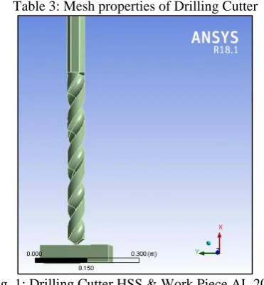
Table 3: Mesh properties of Drilling Cutter
Fig. 1: Drilling Cutter HSS & Work Piece AL 2024
A. Meshing of Drilling Cutter
[image:3.595.323.533.331.525.2]For more accurate result rot the solution domain into an appropriate number of locations. In meshing two considerations are very important detail and refinement.
Fig. 2: Meshing of Drilling Cutter
B. Detail
In this consideration analyze that how much geometric detail is relevant to the simulation. Including the unnecessary detail can greatly increase the effort required to simulation.
C. Refinement
It is also important where in the domain are the most complex. These area required higher densities of mesh elements. But the greater number of element requires more compute resources like memory and processing time. The quality of mesh is defining on the bases of elements and complexity of the geometry. In areas of high geometric complexity mesh element become destroyed. Poor quality element can lead to poor results or in some cases no results.
[image:3.595.56.248.440.534.2]on the stress area increased and it helps to keep more accurate results.
III. RESULTS
A. Analysis
ANSYS is a broadly useful programming, used to mimic collaborations of all controls of physical science, basic, vibration, liquid flow, warmth exchange and electromagnetic for architects.
[image:4.595.46.546.65.628.2] So ANSYS, which empowers to recreate tests or working conditions, empowers to test in virtual environment before assembling models of items. Moreover, deciding and enhancing powerless focuses, figuring life and predicting plausible issues are conceivable by 3D reproductions in virtual environment.
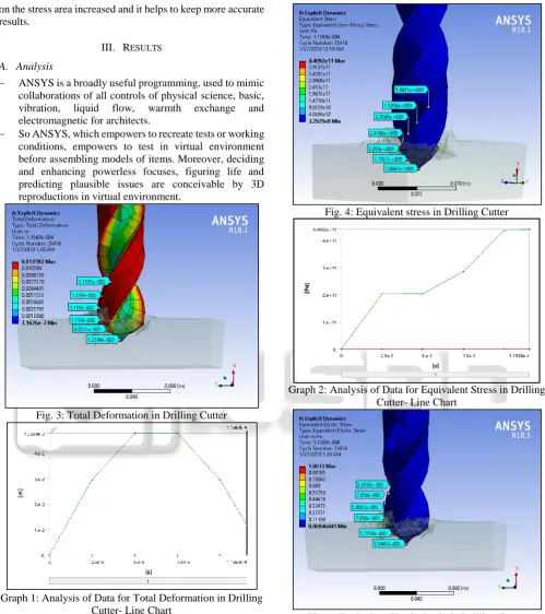
Fig. 3: Total Deformation in Drilling Cutter
Graph 1: Analysis of Data for Total Deformation in Drilling Cutter- Line Chart
Fig. 4: Equivalent stress in Drilling Cutter
Graph 2: Analysis of Data for Equivalent Stress in Drilling Cutter- Line Chart
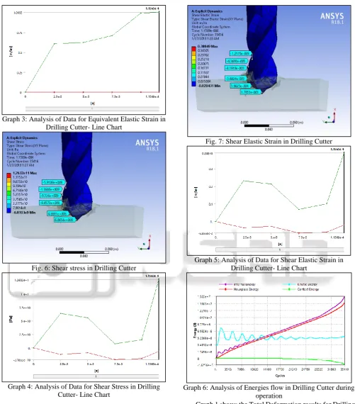
[image:4.595.50.292.248.608.2]Graph 3: Analysis of Data for Equivalent Elastic Strain in Drilling Cutter- Line Chart
Fig. 6: Shear stress in Drilling Cutter
[image:5.595.48.550.61.632.2]Graph 4: Analysis of Data for Shear Stress in Drilling Cutter- Line Chart
Fig. 7: Shear Elastic Strain in Drilling Cutter
Graph 5: Analysis of Data for Shear Elastic Strain in Drilling Cutter- Line Chart
Graph 6: Analysis of Energies flow in Drilling Cutter during operation
Graph 1 shows the Total Deformation results for Drilling Cutter. Maximum Total Deformation generated in Drilling Cutter is 1.1592 × 10-02 m.
Graph 2 shows the Equivalent Stress results for Drilling Cutter. Maximum Equivalent Stress generated in Drilling Cutter is 4.4092 × 10¹¹ Pa.
Graph 3 shows the Equivalent Elastic Strain results for Drilling Cutter. Maximum Equivalent Elastic Strain generated in Drilling Cutter is 1.0033 m/m.
Graph 5 shows the Shear Elastic Strain results for Drilling Cutter. Maximum Shear Elastic Strain generated in Drilling Cutter is 0.38849 m/m.
Graph 6 shows the Internal Energy, Kinetic Energy, Hourglass Energy and Contact Energy flow in Drilling Cutter during operation.
IV. CONCLUSION
In this study, Drilling Cutter process, which is mainly used for producing different holes in drilling process, has been analyzed by Finite Element Method. A simplified and idealized finite element model by using symmetry assumption and a non-simplified finite element model of process have been used in the analyses.
Rectangular section of the Non-linear AL 2024 work piece has been examined. The Total Deformation, Equivalent Stress, Equivalent Elastic Strain, Shear Stress and Shear Elastic Strain exerted by the Drilling tool on the work piece during a machining have been identified in order to control the tool deflection. The aim of study is to predict the effects of cutting parameters on the Drilling Cutter during Drilling operation on AL 2024.
REFERENCES
[1] Sudha J., Sampathkumar S. and Vijaya A, (2009), “AE Waveform analysis of Delamination in GFRP composite materials during drilling”, International Journal of Engineering and Technology Vol. 1, pp. 1793-8236. [2] Kilickap E., (2010), “Determination of optimal
parameter on delamination in drilling of GFRP composites by Taguchi method”, Indian Journal of Engineering and Material sciences, Vol. 17, pp. 265-274. [3] Gaitonde V. N., Karnik S. R. & Davim J. Paulo, (2008), “Taguchi multiple-performance characteristics optimization in drilling of medium density fibre board (MDF) to minimize delamination using utility concept”, Journal of Materials Processing Technology, Vol. 96, pp. 73-78.
[4] Latha B. , Senthilkumar V. S., and Palanikumar, (2011), “Modeling and optimization of process parameter for delamination in drilling GFRP composites”, Machining Science and Technology, Vol. 15, pp. 172–191.
[5] Deng C. and Chin J, (2006), “Hole roundness in deep-hole drilling as analyzed by Taguchi methods”, International Journal of Advanced Manufacturing Technology, Vol. 25, pp. 420–426.
[6] Zhang J. and Chen J., (2009), “Surface Roughness optimization in a drilling operation using the Taguchi method”, Materials and Manufacturing Process, Vol. 2, 59-467.
[7] CCaydass U., Hasccaluk A., Buytoz O.& Meyveci A., (2011), “Performance evaluation of different twist drills in dry drilling of AISI 304 Austenitic Stainless Steel”, Materials and Manufacturing Processes, Vol. 26(8), pp. 951-960.
[8] E. Kuram, B. Ozcelik, E. Demirbas, E. SSik & I. N. Tansel, (2011), “Evaluation of new vegetable-based cutting fluids on thrust force and surface roughness in drilling of AISI 304 using Taguchi method”, Materials
and Manufacturing Processes, Vol. 26(9), pp. 1136-1146.
[9] Gaitonde V. N., Karnik S. R., Achyutha B T & Siddeswarappa B, (2006), “Multi-response optimization in drilling using Taguchi’s quality loss function”, Indian Journal of Engineering and Material Sciences, Vol. 13, pp. 484-484.
[10]Chen M., Liu G., and Zhang X., (2007), “Optimization studies on hole-making tools for high-performance cutting austenitic stainless steel”, Machining Science and Technology, vol. 11, pp. 183–200.
[11]Kilickap E. and Huseyinoglu M., (2010), “Selection of Optimum Drilling Parameters on Burr Height Using Response Surface Methodology and Genetic Algorithm in Drilling of AISI 30 Stainless Steel”, Materials and Manufacturing Processes, vol. 25, pp.1068–1076. [12]Ozcelik B. & Bagci E. (2006), “Experimental and
numerical studies on the determination of twist drill temperature in dry drilling: A new approach”, Materials and Design, vol. 27, pp. 920–927.
[13]Dolinsek S. (2003), “Work-hardening in the drilling of austenitic stainless steels”, Journal of Materials Processing Technology, vol. 133, pp. 63–70.
[14]Kıvak T., Samtas G., Cicek A. (2012), “Taguchi method based optimization of drilling parameters in drilling of AISI 316 steel with PVD monolayer and multilayer coated HSS drills” Measurement, vol. 45, 1547–1557. [15]Meena A. & Mansori M. (2011), “Study of dry and