International Journal of Emerging Technology and Advanced Engineering
Website: www.ijetae.com (ISSN 2250-2459, Volume 2, Issue 3, March 2012)425
A Frequency Band Enhancement of Miniaturized Rectangular
Waveguide Antenna Using Infinity Shaped Split Ring Resonator
Mohamed Ouda
Associate Professor, Electrical Eng. Dep., IUG, Palestine,
Abstract—this paper presents a miniaturized open-ended rectangular waveguide antenna radiating below the cut-off frequency of the waveguide with a large bandwidth. Waveguide miniaturization is achieved by periodically loading the antenna with electromagnetic metamaterials consisting of infinity shaped resonators. The metamaterial cell is designed to have a high effective dielectric permittivity in the frequency region below the cutoff frequency of the waveguide. HFSS software was used to obtain the transmission characteristics of the structure, which are then used to retrieve the effective material properties. Furthermore, the effective dielectric permittivity of the metamaterial cell exhibited a resonance around 5.2GHz. The waveguide antenna was designed and simulated using HFSSTM software. Comparing previous work of miniaturization of waveguides, a higher miniaturization ratio with a bandwidth about 1GHz and good matching is obtained.
Keywords— metamaterial, infinity-shape cell, high permittivity, waveguide antenna, miniaturization, large bandwidth.
I. INTRODUCTION
The physical size of the electromagnetic devices such as antennas and waveguides is an important practical parameter and there is increased need for miniaturization of such devices. In spite of the increasing popularity of planar structure application, the usage of waveguides is inevitable in many applications such as a feeding network for open-ended radiators and a large antenna array. Furthermore, waveguides are employed to fit multi-frequency interlaced antenna arrays and open-ended radiators operating in different frequency into restricted space. The transvers length of the rectangular waveguide is at least half wavelength long and there is increased need for its miniaturization since it is considered to be the biggest disadvantage of waveguides.
There are several ways that can be used for the miniaturization of waveguides. The waveguide cut-off
frequency fc can be decreased by the square root of the
relative permittivity when the waveguide is filled by dielectric materials leading to waveguide miniaturization by the same factor [1].
The cut-off frequency fc can be calculated using equation
(1), where a and b are the inside width and height, respectively, m and n are number of half - wavelength
variations of field in a and b direction, respectively, εr is the
relative permittivity of filing dielectric material in the
waveguide, μr is relative permeability and λc is the
wavelength.
√
√(
)
(
)
,,
(1)
Complex artificial perfect magnetic conductor surfaces can be used for the waveguide walls to reduce its width, [2]. Dielectric loaded hard-walled waveguide that supports TEM propagation was studied theoretically by Mou Kehn and Kildal, [3]. Furthermore, metamaterials can be used to load the waveguide in order to reduce its size. Metamaterials is composed of artificial periodic structures consisting of normal metals and dielectric materials and
possess exotic characteristics such as negative
permeability, negative index of refraction, and negative
permittivity [4]. Marques et. al. investigated guiding
structures miniaturization by loading a rectangular metallic waveguide structure with periodic split ring resonators
(SRRs), [5] that further investigated by Harber et al., [6].
International Journal of Emerging Technology and Advanced Engineering
Website: www.ijetae.com (ISSN 2250-2459, Volume 2, Issue 3, March 2012)426
In this paper, a new design of infinity-shaped split ring resonator structure consisting of two conducting strips over both faces of a substrate is proposed. Open, electric, magnetic and periodic boundary conditions are used in the simulation using ANSOFT’s HFSS software. The S parameters and the retrieved effective material parameters are computed and presented. The robust method presented
by Chen el.al., [9], was used to retrieve the constitutive
effective parameters of metamaterials over the excitation frequency band. The new infinity-shaped resonator exhibits a very high permittivity in the frequency region 4-5.7 GHz. This structure is used to miniaturize an open ended waveguide antenna and is simulated in the frequency range of 4.3-9 GHz.
II. THEORETICAL INVESTIGATIONS AND SIMULATIONS
A. RESONATOR DESIGN AND SIMULATION
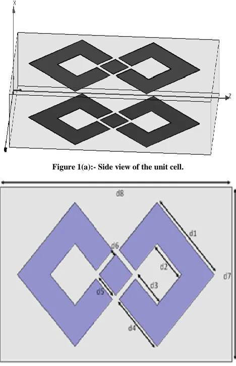
The unit cell structure is shown in figure 1(a). It is constructed of two parallel infinity-shaped copper strips printed over both faces of a dielectric substrate. The copper strip thickness is 0.01mm, the dielectric substrate is FR4-epoxy with relative permittivity, dielectric loss tangent and
thickness of εr=4.4, tanδε=0.02 and t= 1.5 mm respectively.
The top view of the unit cell is shown in figure 1(b) and the dimensions are: - d1=6.44mm, d2=2.76mm, d3=2.39mm, d4=4.22mm, d5=1.84mm, d6=0.37mm, d7=10mm and d8=14.4mm. The Metamaterial unit cell is designed, optimized and simulated using the commercial software package High Frequency Structure Simulator (HFSS). For the simulation, the unit cell is placed inside an air box with dimensions of 14.4 mm × 10mm × 2.5 mm, Time varying
electromagnetic field having E vector along y axis, H
vector along z axis, propagating along x axis is used to excite the cell. Perfect Electric Conductor (PEC) was applied at the surfaces of constant y. Perfect magnetic conductor (PMC) boundary condition was applied at the surfaces of constant z. At the remaining two boundaries, open boundary condition was applied [10]. The simulation was done in the frequency band 4GHz -12GHz with 0.05GHz increment. The method given in [9] and [11] was used to calculate the effective parameters of the medium from the calculated S parameters. Then, the relative permittivity and permeability were computed from the
equations of ε = n / z and μ = n × z where n and z are the
refractive index and the wave impedance, respectively.
Figure 1(a):- Side view of the unit cell.
Figure 1(b):- Top view of the unit cell.
The magnitude and phase of transmission and reflection coefficient characteristics of the infinity shaped resonator
were computed using simulated S21 and S11 parameters,
respectively and are shown in figure 2. The transmission peaks and the reflection dips appear at 4.05GHz and 9.75GHz, and the transmission dip and the reflection peak appear at 5.1GHz. This is considered as indication that there are resonant frequencies at those regions. The other
electromagnetic characteristics such as refractive index (n),
permeability (µ) and permittivity (ε) of the infinity shaped
[image:2.612.327.561.137.500.2]International Journal of Emerging Technology and Advanced Engineering
Website: www.ijetae.com (ISSN 2250-2459, Volume 2, Issue 3, March 2012)427
(a)
(b)
Figure 2:- (a) Magnitude of S11 and S21, (b) Cumulative angle Phase of S11 and S21.
(a)
(b)
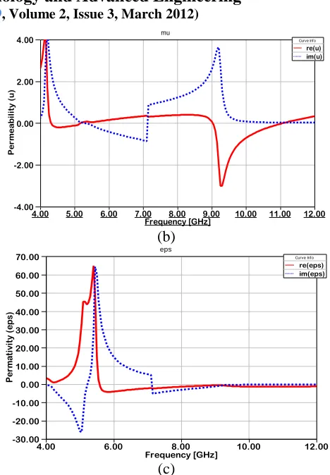
[image:3.612.326.560.115.452.2](c)
Figure 3:- Real and imaginary parts of (a) refractive index, (b) permeability and (c) permittivity of the metamaterial.
The real part of the refractive index has positive value in the lower frequency range up to 7.15GHz and negative values from 7.15GHz to 11.6GHz, as shown in figure 3(a). That is due to the cascaded resonant frequencies at 7.15GHz and 11.6GHz.
The real parts of permittivity and permeability have negative and positive values over the frequency range and it can be said that negative permittivity has wider frequency band than the permeability. But it can be noticed that n has negative values at some regions where the real part of
permeability µ' is positive and the real part of permittivity
ɛ' is negative, at this case n is called single negative refractive index. The refractive index n can have negative
values without the simultaneous negative values of µ' and ɛ'
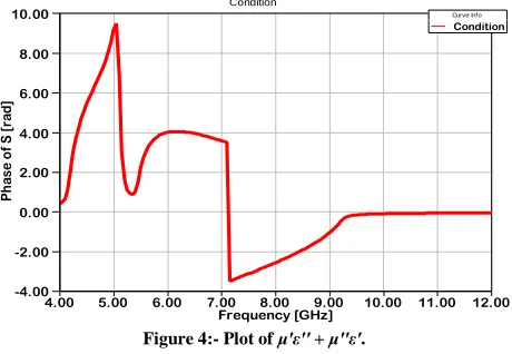
if the condition μ'ε'' + μ''ε' < 0 is satisfied, [12]. This
condition is plotted and is shown in figure 4. It can be seen that this condition is applied well to the infinity-shaped
split ring resonator. Therefore it is acceptable for n to have
negative values at this region.
4.00 5.00 6.00 7.00 8.00 9.00 10.00 11.00 12.00
Frequency [GHz] -6.00
-4.00 -2.00 0.00 2.00 4.00 6.00
Ph
a
se
o
f S [
ra
d]
Ang(S11,S21)
Curve Info
cang_rad(S11) cang_rad(S21)
4.00 5.00 6.00 7.00 8.00 9.00 10.00 11.00 12.00
Frequency [GHz] -3.00
-2.00 -1.00 0.00 1.00 2.00 3.00 4.00
R
e
fr
a
c
ti
ve
in
de
x (
n
)
n
Curve Info
im(n) re(n)
4.00 5.00 6.00 7.00 8.00 9.00 10.00 11.00 12.00
Frequency [GHz] -4.00
-2.00 0.00 2.00 4.00
Pe
rm
e
a
bi
li
ty (
u
)
mu
Curve Info
re(u) im(u)
4.00 6.00 8.00 10.00 12.00
Frequency [GHz] -30.00
-20.00 -10.00 0.00 10.00 20.00 30.00 40.00 50.00 60.00 70.00
Pe
rm
at
ivi
ty (
eps)
eps
Curve Info
[image:3.612.55.285.513.689.2]International Journal of Emerging Technology and Advanced Engineering
Website: www.ijetae.com (ISSN 2250-2459, Volume 2, Issue 3, March 2012)428
[image:4.612.330.559.193.343.2]The real parts of the relative permittivity exhibits a very phenomenon in the lower frequency range since it increase from 1.3 at 4.25GHz up to 65 at 5.45GHz. This phenomenon is employed in the design of a miniaturized open ended waveguide antenna.
Figure 4:- Plot of μ'ε'' + μ''ε'.
B. WAVE GUIDE ANTENNA DESIGN AND SIMULATION
The wave guide antenna simulated is operating at X-band (cutoff frequency 6.6GHz) with dimensions 22.86mm x 60mm x 10.16mm. The waveguide is excited by C-band waveguide-to-coaxial transition (cutoff frequency 4.3GHz) with dimensions 35mm x 25mm x 15mm. HFSS software is used for the simulation of the waveguide over frequency range from 4.3GHz to 9GHz. Furthermore, the X-band waveguide was loaded by an array of 6 infinity-shaped metamaterial cells.
The longitudinal propagation factor of this waveguide in a lossless case is given by a simple set of equations, [6],
where the waveguide propagation factor kz changes as the
permittivity and permeability change, equation (2).
kz=±k0√
[ (
)
]
, =
√ , =
,
m=1, 2, 3 … (2)
where k0 is the free space propagation factor, εr is the
relative permittivity, μtr is the relative permeability in the
transverse direction, μLr is the relative permeability in the
longitudinal directions, a is waveguide’s width, f is
frequency of incident wave, fco and fc are the cut-off
frequencies of the empty and the loaded waveguides, respectively. The loaded waveguide model built using HFSS software is shown in Figure 5.
The first cell was placed out from the X-band waveguide to ensure the excitation of the first cell in the array. The last cell was placed out from the open end of the waveguide in order to improve the radiation.
Figure 5:- Loaded waveguide model.
Reflection coefficient S11 at the input port of the loaded
[image:4.612.54.284.206.365.2]waveguide antenna was plotted, Figure 6, and compared with that of the empty waveguide. From the plot, one can notice that the propagation passband is located well below the cutoff frequency of the X-band waveguide with cutoff frequency 4.65GHz, bandwidth of 1GHz, bandwidth reduction about 2GHz and minimum return loss about -19.6dB at 5.3GHz.
Figure 6:- Return loss for empty, and metamaterial loaded wave guide.
Existence of the passband below the cutoff frequency of the waveguide is due to the increase of the effective permittivity of the medium inside the waveguide.
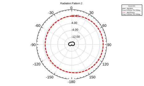
Figures 7 and 8 show E-plane and H-plane patterns of the
waveguide antenna at 4.65GHz, respectively. It is clear that the antenna at the resonant frequency radiate like an omini-directional antennas.
4.00 5.00 6.00 7.00 8.00 9.00 10.00 11.00 12.00
Frequency [GHz] -4.00
-2.00 0.00 2.00 4.00 6.00 8.00 10.00
Ph
ase
o
f S [
ra
d]
Condition
Curve Info
Condition
4.00 5.00 6.00 7.00 8.00 9.00
Frequency [GHz] -30.00
-25.00 -20.00 -15.00 -10.00 -5.00 0.00
S
1
1
(
d
B
)
S11(Empty & with Metamaterial)
[image:4.612.330.559.456.609.2]International Journal of Emerging Technology and Advanced Engineering
Website: www.ijetae.com (ISSN 2250-2459, Volume 2, Issue 3, March 2012) [image:5.612.52.285.312.452.2]429
Figure 7:- E-plane radiation pattern for metamaterial loaded waveguide antenna (solid – co-polarized, dotted – cross-polarized).
Figure 8:- H-plane radiation pattern for metamaterial loaded waveguide antenna (solid – co-polarized, dotted – cross-polarized).
III. CONCLUSION
The infinity shape metamaterial cells were designed and used to miniaturize the open-ended waveguide radiator. The effective permittivity of the material increases up to 70 in the cutoff band of the waveguide. The antenna is able to radiate below the cutoff frequency of the waveguide as a results of effective permittivity. Simulation of infinity shape loaded X-band waveguide antenna radiating below the cutoff frequency was successfully carried out. According to simulations, the cutoff frequency is 4.65GHz, 2.GHz below the cutoff frequency of the unloaded waveguide, a minimum return loss of -19dB at 5.3GHz and bandwidth of 1GHz. Comparing previous work of miniaturization of waveguides, a higher miniaturization ratio with a bandwidth about 1GHz and good matching are obtained.
REFERENCES
[1] C. A. Balanis, 1989, Advanced Engineering Electromagnetics. New York: Wiley.
[2] Y. Fei-Ran, M. Kuang-Ping, Q. Yongxi, and T. A. Itoh, 1999, ―Novel TEM waveguide using uniplanar compact photonic-bandgap (UC-PBG) tructure,‖ IEEE Trans. Microw. Theory Tech., vol. 47, no. 11, pp. 2092–2098.
[3] M. Ng Mou Kehn and P.-S. Kildal, 2003, ―The N-guide: A novel miniaturized hard quasi-TEM waveguide,‖ in Proc. IEEE Antennas and Propagation Society International Symposium, vol. 2, pp. 1111– 1114.
[4] R. A. Shelby, D. R. Smith, S. C. Nemat-Nasser and S. Schultz, 2001, ―Microwave Transmission through a Two Dimensional, Isotropic, Left-Handed Metamaterial‖. Applied Physics Letters, vol. 78, pp. 489-491
[5] R. Marques, J. Martel, F. Mesa, and F. Medina, 2002, ―Left-handed-media simulation and transmission of EM waves in subwavelength split-ring-resonator-loaded metallic waveguides,‖ Phys. Rev. Lett., pp. 183 901–183 904.
[6] Silvia Harbar, Juraj Bartolic, Zvonimir Sipus, 2005, ―Waveguide Miniaturization Using Uniaxial Negative Permeability Metamaterial‖, IEEE Transactions on Antennas And Propagation, VOL. 53, NO. 1.
[7] J.-X. Niu, X.-L. Zhou, and L.-S. Wu, 2007, ―Analysis and application of novel structures based on split ring resonators structures based band on split ring resonators and coupled lines‖ Progress In Electromagnetics Research, PIER 75, 153–162.
[8] M. Ouda and N. Abutahoun, 2012 ―A Novel Infinity Shaped Split Ring Resonator to Form a New Metamaterial‖, The Islamic University Journal (Series of Natural Studies and Engineering), In Press.
[9] X. Chen, T. M. Grzegorczyk, B.-I. Wu, J. Pacheco, J. A. Kong, 2004 ―Robust method to retrieve the constitutive effective parameters of metamaterials‖. Physical Review E, Vol. 70, No. 1, p: 016608.1– 016608.7.
[10]K. Aydın, 2008, ―Characterization and Applications of Negative-Index Metamaterials‖, Department of Physics, Bilkent University, Ankara, Turkey.
[11]D. R. Smith, D. C. Vier, Th. Koschny, C. M. Soukoulis, 2005, ―Electromagnetic parameter retrieval from inhomogeneous metamaterials‖, Physical Review E, Vol. 71, No. 3, pp. 036617.1– 036617.11,
[12]T. T. Nguyen, P. Lievens1, Y. P. Lee and D. L. Vu, 2011, ―Computational studies of a cut-wire pair and combined metamaterials‖. Advances in Natural Sciences: Nanoscience and Nanotechnology. Vol. 2, No. 3, p: 9.
-28.00 -16.00 -4.00 8.00
90 60 30 0
-30
-60
-90
-120
-150
-180 150
120
Radiation Pattern 1
Curve Info dB(rEPhi) Freq='4.65GHz' Theta='90deg'
dB(rETheta) Freq='4.65GHz' Theta='90deg'
-12.00 -4.00 4.00 12.00
90 60 30 0
-30
-60
-90
-120
-150
-180 150
120
Radiation Pattern 2
Curve Info dB(rEPhi) Freq='4.65GHz' Phi='90deg'