International Journal of Emerging Technology and Advanced Engineering
Website: www.ijetae.com (ISSN 2250-2459,ISO 9001:2008 Certified Journal, Volume 4, Issue 5, May 2014)
139
Efficient PV Inverter With Quasi Z Network Using RL Load
S. Midhusha
1, Ragubathi .D
2, Ashok Rangaswamy
31,2PG Scholar, Sri Shakthi Institute of Engineering & Technology, L&T Bypass Road ,Coimbatore-62, Affiliated to Anna
University of Chennai 3
T Assistant Professor/Department of EEE, Sri Shakthi Institute of Engineering & Technology, L&T Bypass Road, Coimbatore-62, Affiliated to Anna University of Chennai
Abstract—The proposed PV inverter overcomes various
problem of present PV inverter, due to the inclusion of Quasi Z network and matrix converter in the PV system. Combination of these circuit in PV system has various significant advantages such as voltage and frequency doublers capability, reduced harmonic content with proper current and voltage regulation. Other merits includes it is a Single stage conversion process with Zero voltage turn on and soft turn off which in turn reduces the voltage stress and switching losses in the PV system. This proposed PV inverter is connected to PMSM through Quasi Z network which is replacement of DC link. The presence of bulky electrolytic capacitor as DC link is most unreliable component for most of the inverter’s failure, particularly at high temperature. Thus this replacement of circuit significantly improves the efficiency and reliability of complete system. This is proved in the satisfactory performance observed by RL load connected to the PV inverter using MATLAB software and hardware implementation.
Keywords—Photovoltaic (PV) inverter, Quasi Z network,
Zero voltage turn on, soft turn off.
I. INTRODUCTION
Due to depletion of fossil fuels and conventional energy crisis has steadily increased the environmental concern. This concern has led to major interest in exploiting the renewable form of energy for the generation of electrical power. Most promising energy is the Solar and Wind. Whereas Solar has high reliability with least 20 years of servicing time, As there is no moving or rotating part involved. The main characteristic in the renewable energy is that they are found abundance in nature, they can be renewed and certain drawback is that they are uncontrolled and continuously fluctuating which is true for wind. The special techniques and control algorithm is developed in power electronics area for proper regulation of the electrical power produced and maximization of extracting power. The solar energy can be used through the Photo voltaic effect i.e. converting the solar energy into electrical energy. Due to the PV system scalability and portability it has good modulation. In past design, centralized converter based PV system was a widely used type.
This module were connected to three phase voltage source, and in order to reduce the harmonic content, the inverter’s each output phase was connected to LC filter. A three phase transformer either for step up or step down voltage capability also provides galvanic isolation is connected to the utility side low frequency transformer which makes the complete system big and reduce the efficiency of the system[1],[5],[6]. To avoid this later came multiple stage conversion system which was widely used in PV system. In spite of having good boosting capability multiple stage conversation system also have drawback such as reduced power density and low efficiency. With recent developments in power electronic field high reliability and high efficiency converters are used for various renewable technology application. The utilization of various innovative scheme and sophisticated control algorithm has led to improvement in energy production and quality of operation. The proposed topology presents in this paper is successfully applied to the PV inverter connected to the PMSM drive. They can be used in high power application with the variation of rating in bidirectional switch used.
The PV inverter are the type of inverter which converts the DC power of solar into AC power for commercial or residential use and grid power. They also have special feature for extraction of maximum power from the solar through various algorithm such as P&O or Incremental conductance method etc which is also called as Maximum power point tracking(MPPT)Techniques They are by adjusting the voltage and current supplied from the PV panel.
PV panel power is directly related to intensity of sunlight which is affected daily by sun shades from nearby object (i.e. trees, utility poles, tall buildings), clouds etc. PV inverters are designed to operate over wide range of voltage to capture power during lower light intensity.
International Journal of Emerging Technology and Advanced Engineering
Website: www.ijetae.com (ISSN 2250-2459,ISO 9001:2008 Certified Journal, Volume 4, Issue 5, May 2014)
140
The third major component is to maximize the power output of solar installation is to utilize high efficiency of PV inverters. Efficiency is termed as the measure of power out of the inverter as a percentage of the power into the inverter. High efficiency of PV inverters use less of power in the conversion process and supply more power for the ease of use.
II. SURVEY OF EXISTING SYSTEMS
Integral part of distribution system is power electronics, with help of which they convert the generated electricity into utility-compatible forms. However, the addition of power electronics usually adds reliability issues as well as costs. [1], [2]. Referring to the report by Sandia National Laboratories [3], which in Most of the PV system problems faced in the field is that they are complex and costly. The inverter failure leads to unreliable PV system which in turn leads to loss of hope in renewable technology. Therefore, to achieve success for long term in PV system, new power converters with higher reliability and efficient long life time are required [3] [4].
In past design used, centralized converter-based PV system was the most commonly used type of PV system. The system, PV modules are connected to 3phase voltage-source inverter. The output of each phase has an LC filter which is used to limit the harmonics. A 3phase transformer, which is used to step up the voltage and provides a galvanic isolation, which connects the inverter to the utility.
Actually low frequency transformers are considered poor equipment mainly due to their large size and low efficiency. To avoid this low frequency transformers PV system use multiple stage conversion system [1], [5], [6].The most common scheme, includes dc to ac voltage source inverter and dc to dc converter. Commonly, the dc to dc converter contain Offering a high boosting capability and galvanic isolation, this converter produce low efficiency overall due to the presence of Multiple-stage conversion system. Moreover, bulky electrolytic capacitor is needed for dc link. Electrolytic capacitors, which are very sensitive to the temperature, may cause reliability problem to the overall system.
The PV inverter which consists of electrolytic capacitor does not provide the same life time as PV modules. Consequently, the PV system requires frequent replacement of the inverter. In order to overcome all the above mentioned problem it is essential to take up a alternative inverter design topologies so as to make the
inverter economical while also increasing their
reliability[7].There are several solution proposed to overcome the problem partially.
Reference [5] implemented a transformer-less scheme in which ground leakage current is minimized, but it had a drawback that voltage cannot be changed for wide range. Reference [9] introduced an integrated solution for PV/FC based hybrid distributed generation system to eliminate the requirement of high voltage buffer capacitor for inverters; this inverter does not provide isolation. In [10], small film capacitors replaced the large electrolytic capacitor. This proposed network is applicable for both low and medium power application.
III. QUASI Z-NETWORK
The quasi Z inverter is a single stage power converter developed from Z source inverter scheme, Which employs a unique impedance network. The conventional VSI and CSI has a drawback that Triggering two switches of same leg of phase leads to short-circuiting and also the maximum output obtained cannot exceed the DC input, Since they are buck converter and produce a voltage lower than the DC input voltage. Whereas both Z source and quasi network overcomes the above mentioned drawback; by utilizing several shoot through Zero states. The Quasi Z network is different than that of Z Source inverter in the LC impedance network interfaced between the source and the inverter which is shown in Fig1..The unique design of this network, i.e. LC and diode network connected to the matrix converter modify the operation of the circuit, allowing the shoot through state which is forbidden in traditional VSI. This network will effectively protect the circuit from damage when the shoot through occur and by using the shoot through state and that network boost the link voltage.
A Zero state is produced when both upper and lower switches of same leg is fired simultaneously to boost the output voltage. Sustaining the six permissible active switching state of conventional VSI, the zero state can be partially or completely replaced by the shoot through state depending upon the boosting voltage requirement. This quasi Z network has all the advantage of Z source inverter with both voltage boost and inversion capability in single stage. By using this new network, the inverter draws a constant current from the PV panel and is capable of handling a wide voltage range in input side. It also features reduced switching ripples to the PV panel, lower the component rating, cause low EMI problems and reduced source stress compared to the traditional ZSI.
International Journal of Emerging Technology and Advanced Engineering
Website: www.ijetae.com (ISSN 2250-2459,ISO 9001:2008 Certified Journal, Volume 4, Issue 5, May 2014)
141
Moreover, the Zero voltage turn on and soft turn off results in low voltage stress on the switches.
Fig.1. The proposed circuit Quasi Z network connected between single phase inverter and matrix converter.
IV. MATRIX CONVERTER
The basic feature of the matrix converter has several advantages over traditional rectifier-inverter type power frequency converters. They provide sinusoidal output waveform with minimum higher order harmonics and no sub harmonics. It also has bidirectional energy flow capability. Here the power factor can be fully controlled. Matrix converter has a minimal energy storage requirements, which allows to get rid of life time limited and bulky energy storage capacitor. Matrix converter has no output frequency limit, but has limit in the amplitude. This overcome of limitation is done using modulation technique. The matrix converter replace the two energy conversion stage with only single stage energy conversion because it has no energy storage element present. The converter use special bidirectional semiconductor switches. The switches which have blocking voltage and conducting current capability in both directions. This bidirectional switch consist of a pair of device with turn on capability, are usually Insulated gate bipolar transistor (IGBT),they are either a common collector or common emitter back to back arrangement. Usually each IGBT is connected to a anti-parallel diode. They have array of bidirectional
semiconductor switches whichisshowninFig1 .They
connect all input line to all the output line. With the help of matrix converter it is instantaneous power in the input is same as the power in the output side. They are also used in controlling the phase angle between the voltage and current in the input or the output phase angle differ from the input phase.
The other advantage is that form of waveform id independent. So the input can be Three phase AC and output DC, or both could be DC, or both AC. Both form AC waveform is used in this paper for the RL application.
V. MODE OF OPERATION
In this paper the figure.1 shows the complete PV system connected to a resistive load for simple analysis. The load can be any adjustable speed drives used in commercial or industrial application. The system results in efficient and reliable result in three phase application in renewable technology. The dc source can also be replaced by the irradiance term which is used for obtaining variable DC. This DC power is converted to AC. Through a single phase inverter which comprise of 4 bidirectional switches. This AC single phase voltage is doubled with proper regulation, reducing the harmonic content to the matrix converter. In order to have proper conversion of single phase ac to three phase ac wave, matrix converter is used. The matrix converter used in this paper makes the complete system compact in structure and they directly convert the ac to ac power through a controlled bidirectional switches.
The output ac signal’s magnitude and frequency is varied according to the application in single stage itself. Matrix converter topology volume is also compact when compared to the PWM-VSI. In addition to compact size and volume, the input current drawn has unity displacement factor as well as harmonic reduced sinusoidal output currents. This matrix converter operates in high surrounding temperature due to the lack of electrolytic capacitor, which is very vulnerable to the temperature. They also have very long life span.
Operation of this system can be broadly divided as
• Charging mode and
• Discharging mode for the quasi-Z network
A. Charging Mode
International Journal of Emerging Technology and Advanced Engineering
Website: www.ijetae.com (ISSN 2250-2459,ISO 9001:2008 Certified Journal, Volume 4, Issue 5, May 2014)
142
B. Discharging Mode
In this mode the voltage flows through the bidirectional switches, from to and bottom of different leg in order to produce proper amplified three phase output voltage and current. The average current through the inductors in both configuration have same value, which is give by,
Il=P/Vin (1)
In the above equation the P is the system power rating and Vin is the input voltage. Here the current is maximum on shoot through state. The capacitance of the Quasi Z network C1 and C2 is represented as,
C1 = C2 = (2.P.Ds)/(0.03.Vin.Vdc.f)
= P / (0.015.Vin2.f).Ds.(1-2Ds) (2)
VI. SIMULATION AND DISCUSSION
This section provides the simulation of the entire PV inverter connected to the Permanent magnet synchronous motor. The Permanent magnet synchronous motor is widely used because of its effective construction and operation. This PMSM has various advantages which makes them widely used in industries or in various renewable application. The PMSM has permanent magnet as the rotor and is free from field winding and external excitation; this in turn results in low volume and compact size.
The system has front end which is termed as PV energy harvesting .Here the PV panel is represented by irradiance, which produce variable dc voltage. And the MPPT is used to extract maximum power and then provide to the quasi Z network. The subsystem, represents front end which is PV harvesting i.e. front end that comprise of PV panel and the MPPT technique to extract maximum power from the PV module and this is connected to the Quasi Z network. And another subsystem is simplified block of matrix converter. This is then connected to permanent magnet Synchronous motor.
A. Front End-PV Harvesting
This section consist of DC source with 30 V and then obtained 60V maximum extraction through MPPT algorithm .This maximum power point tracking is essential in all the PV inverters. In this proposed PV inverter can perform MPPT as it follows any references within it range i.e. In this for simulation purpose 100V varying value in order to represent PV panel. For example if the irradiance drops within a referred limit The temperature will be assumed as standard value and is vice versa when irradiance increases.
B. Back End-Matrix Converter
[image:4.612.334.556.339.450.2]The simulation set up for the back end section matrix converter, circuits are designed and are represented in subsystem for the convenience and are simulated with feedback loop provided. Current feedback is provided so as to obtain error free output. The matrix converter comprises of bidirectional switches structured in compact form. They are connected with the controller in order to have better switching sequence so as to provide amplified proper alternating three phase power. Proposed PV inverter has a significant advantage that without filter present in load side this matrix converter has an capability to reduce the harmonic content in the output. When they are connected to RL load the output has low harmonic present in it with good boosting capability.
TABLE I
Performance Evaluation And Comparison
Without Quasi Z network
With quasi Z network Input
voltage(v)
Voltage for LC the network(v)
Input voltage (v)
Voltage for Quasi network (v)
10 100 10 340
20 150 20 400
30 200 30 500
[image:4.612.333.554.536.681.2]In this PMSM can also be used as the load foe efficient operation. The stators winding of permanent magnet synchronous machine are connected in WYE to an internal neutral point. This three phase machine has sinusoidal back EMF waveform. The rotor is set round in the Simulink configuration.
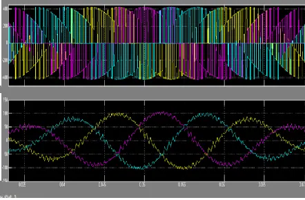
Fig.2 Voltage and Current waveform for RL load connected PV inverter
International Journal of Emerging Technology and Advanced Engineering
Website: www.ijetae.com (ISSN 2250-2459,ISO 9001:2008 Certified Journal, Volume 4, Issue 5, May 2014)
[image:5.612.52.284.115.228.2]143
Fig.3 Output of PMSM -Constant rotor speed
A. Hardware Implementation
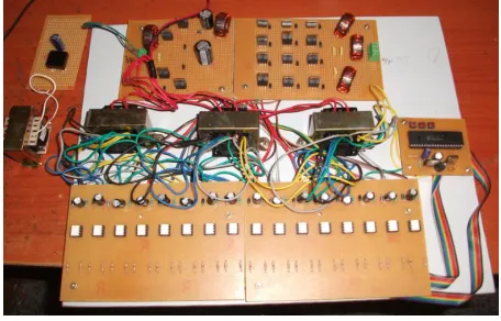
The hardware prototype consist of driver circuit, PIC controller connect to matrix converter and quasi network. The switches used are MOSFET. The 230 V AC is step down to 12V using step down transformer and are converted to constant 5V using 7805 regulator. The transformer used is a multi-tapping transformer. The transformer’s output is fed to controller and the driver circuit used to generate desired PWM switching pulse for switch to operate. The hardware prototype is shown in Fig.4
Fig .4 Hardware implementation
VII. CONCLUSION
This paper presented a very reliable and compact way using efficient PV inverter which has inclusion of Quasi Z network with matrix converter. The merits of implementing this topology is that it is a single stage conversion system, boosting up the voltage with low harmonic content. This matrix converter produce proper sinusoidal waveform low harmonics in the output side which is very much required for driving RL load in efficient way.
The comparative performance is analysed in system with and without quasi Z network which in turn concludes the efficient boosting capability approximately 2.6 times and long life span. This is observed by simulating in MATLAB and hardware prototype is implemented.
REFERENCES
[1] S. Atcitty, J. E. Granata, M. A. Quinta, and C. A. Tasca, Utility-scale gridtied PV inverter reliability workshop summary report, Sandia National Labs., Albuquerque, NM, USA, SANDIA Rep.
SAND2011-4778.[Online].Available:http://energy.sandia.gov/wp/wpcontent/gall ery/uploads/Inverter_Workshop_FINAL_072811.pdf
[2] S. Chakraborty, B. Kramer, and B. Kroposki, ―A review of power electronics interfaces for distributed energy systems towards achieving low-cost modular design,‖ Renew. Sustain. Energy Rev., vol. 13, no. 9, pp.2323–2335,Dec.2009.
[3] Y. C. Qin, N. Mohan, R. West, and R. Bonn, Status and needs of power electronics for photovoltaic inverters, Sandia National Labs., Albuquerque, NM, USA, SANDIA Rep. SAND2002-1535. [Online]. Available:www.prod.sandia.gov/techlib/access
control.cgi/2002/021535. pdf
[4] Y. Huang, F. Z. Peng, J. Wang, and D. W. Yoo, ―Survey of the power conditioning system for PV power generation,‖ in Proc. IEEE PESC, Jun.18–22,2006,pp.1–6.
[5] T. Kerekes, R. Teodorescu, P. Rodríguez, G. Vázquez, and E. Aldabas, ―A new high-efficiency single-phase transformerless PV inverter topology,‖ IEEE Trans. Ind. Electron., vol. 58, no. 1, pp. 184–191, Jan. 2011.
[6] G. Eason, B. Noble, and I. N. Sneddon, ―On certain integrals of Lipschitz-Hankel type involving products of Bessel functions,‖ Phil. Trans. Roy. Soc. London, vol. A247, pp. 529–551, April 1955. (references)
[7] J. Clerk Maxwell, A Treatise on Electricity and Magnetism, 3rd ed., vol. 2. Oxford: Clarendon, 1892, pp.68–73.
[8] I. S. Jacobs and C. P. Bean, ―Fine particles, thin films and exchange anisotropy,‖ in Magnetism, vol. III, G. T. Rado and H. Suhl, Eds. New York: Academic, 1963, pp. 271–350.
[9] K. Elissa, ―Title of paper if known,‖ unpublished.
[10] R. Nicole, ―Title of paper with only first word capitalized,‖ J. Name Stand. Abbrev., in press.
[11] Y. Yorozu, M. Hirano, K. Oka, and Y. Tagawa, ―Electron spectroscopy studies on magneto-optical media and plastic substrate interface,‖ IEEE Transl. J. Magn. Japan, vol. 2, pp. 740–741, August 1987 [Digests 9th Annual Conf. Magnetics Japan, p. 301, 1982]. [12] M. Young, The Technical Writer's Handbook. Mill Valley, CA:
[image:5.612.54.282.373.519.2]