Abstract
Analysis of different modulation techniques for reverse voltage nine level inverter is discussed in this paper. Reverse voltage topology requires fewer components compared to existing inverter Topologies and requires fewer carrier signals and gate drives. Therefore, the overall cost and complexity are greatly reduced particularly for higher output voltage levels. Multi carrier Sine Pulse Width Modulation (SPWM) techniques are widely used for different multilevel inverter topologies. The chosen multilevel inverter is simulated for various multicarrier based Pulse Width Modulation (PWM) techniques and selective harmonic elimination method. The multicarrier SPWM techniques include In Phase Disposition (PD) PWM, Alternative Phase Opposition and Disposition (APOD) PWM and Variable Frequency (VF) PWM. It is observed that sinusoidal reference with Alternative Opposition and Disposition (APOD) provides output with relatively low distortion.
Keywords: Multilevel inverter, reduced number of switch, Reverse voltage topology, Selective harmonic elimination, SPWM
________________________________________________________________________________________________________
I. INTRODUCTION
The multilevel inverters are used in high power and high voltage industry. The main advantages of multilevel inverters are lower Total Harmonic Distortion (THD), less stress on the power switches and higher efficiency. The harmonic content of the output decreases as the number of level increases. There are mainly three types of multilevel inverters named as diode clamped multilevel inverter, flying capacitor multilevel inverter and cascaded multilevel inverter. Each of these topologies has a different mechanism for providing the required voltage levels. But the number of main switches in each topology is equal. The main disadvantage is the increase in number of power switches that normally contributes to the complexity in controlling the power switches. Many methods have been developed to decrease the number of switches. Among them one is reverse voltage topology. The advantage of using Reverse Voltage Topology is that reduced the number of switches which reduced the complexity in gate drives circuit as well as reduced the number carrier signals in SPWM technique.
In this paper, presented the comparative analysis on MCPWM and SHEPWM method for valuation of harmonic elimination and shown the THD result in Reverse voltage multilevel inverter. Multi-Carrier Pulse Width Modulation (MCPWM) strategies is widely used, because it can be easily implemented to low voltage modules. Normally MCPWM can be categorized as Level Shifted PWM (LS-PWM) and Phase Shifted PWM (PS-PWM) methods. The LS-PWM is characterized into Phase Disposition (PD), Phase Opposition Disposition (POD) and Alternative Phase Opposition Disposition (APOD). Equate the above all methodology, APOD method is the most major process to express harmonics are centered as sidebands around the carrier frequency. Merits of APOD approach in MCPWM have no harmonics occur at the carrier frequency and higher band width the main objective of SHEPWM method is to determine the switching angles to specific lower order harmonics suppressed in the output voltage of the inverter to achieve desired fundamental component with possible minimum THD.
II. DESCRIPTION OF REVERSE VOLTAGE MULTILEVEL INVERTER
This topology is a hybrid multilevel topology which separates the output voltage into two parts. 1) Level generation part
2) Polarity generation part
Fig. 1: Single phase nine level reverse voltage inverter with reduced number of switches
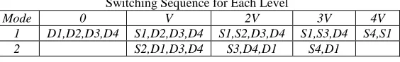
Fig.1 shows that nine inverter requires eight switches and four DC sources. The left portion of the circuit in Fig.1 generates the required output levels and the right portion of the circuit generates the polarity of the output voltage. The right portion of the circuit is called polarity generation part; it reverses the output of the level generation part when the voltage polarity requires to be changed for negative polarity. This topology requires fewer components in comparison to conventional inverters. Reduced number of switches leads to reduced cost and complexity. This also leads to reduced losses and increased efficiency. Another advantage of the topology is that it just requires half of the conventional carriers for SPWM controller. SPWM for nine -level conventional converters consists of eight carriers, but in this topology, four carriers are sufficient. Table I show the switching sequence for each level. According to the table, there are eight possible switching patterns to control the inverter. It shows the great redundancy of the topology. However, as the dc sources are externally adjustable sources (dc power supplies), there is no need for voltage balancing for this work.
Table – 1
Switching Sequence for Each Level
Mode 0 V 2V 3V 4V
1 D1,D2,D3,D4 S1,D2,D3,D4 S1,S2,D3,D4 S1,S3,D4 S4,S1
2 S2,D1,D3,D4 S3,D4,D1 S4,D1
III. MODULATION TECHNIQUES
Multicarrier Pulse Width Modulation
1) In Phase Disposition (PD) PWM
2) Alternative Phase Opposition and Disposition (APOD) PWM 3) Phase Opposition Disposition with Variable Frequency (VF) PWM
Selective Harmonic Elimination PWM
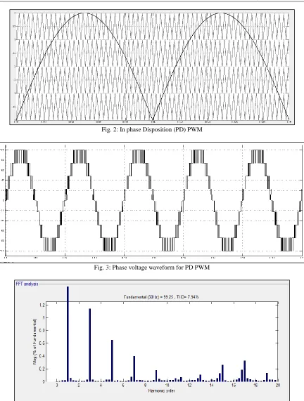
In Phase Disposition (PD) PWM
Fig. 2: In phase Disposition (PD) PWM
Fig. 3: Phase voltage waveform for PD PWM
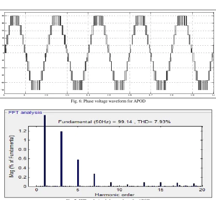
Fig. 4. FFT analysis for PD PWM Alternative Phase Opposition and Disposition (APOD) PWM
Fig. 5: Alternative phase opposition and disposition (APOD) PWM
Fig. 6: Phase voltage waveform for APOD
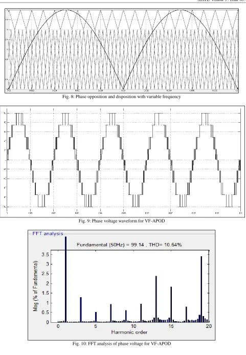
Fig. 7: FFT analysis of phase voltage for APOD Phase Opposition Disposition with Variable Frequency (VF) PWM
Fig. 8: Phase opposition and disposition with variable frequency
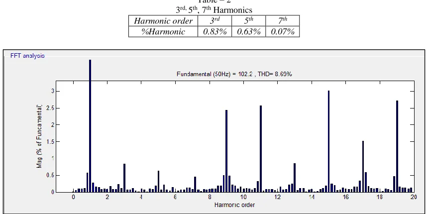
Fig. 11: Phase voltage waveform for SHE-PWM Table – 2
3rd, 5th, 7th Harmonics Harmonic order 3rd 5th 7th
%Harmonic 0.83% 0.63% 0.07%
Fig. 12: FFT analysis of phase voltage for SHE-PWM
IV. RESULT AND COMPARISON
In table 3, different PWM modulation technique is compared. Table – 3
PWM method THD% Fundamental Voltage (Peak) Rms value of fundamental voltage
PDPWM 7.94 99.25 70.18
APODPWM 7.93 99.14 70.10
APOD-DF PWM 10.64 99.14 70.07
Technology, Vol. 8(23), January 2015.
[4] Jithinmon Rajan Philip and Lallumol K. Johny, “Reversing Voltage Reduced Switch Multilevel Inverter” International Journal of Engineering Technology, Management and Applied Sciences Volume 3, Issue 8, ISSN 2349-4476 August 2015.
[5] Subhransu Sekhar Dash1, P.Palanivel2 and S.Premalatha3, “Performance Analysis of Multilevel Inverters Using Variable Switching Frequency Carrier Based PWM Techniques”, International Conference on Renewable Energies and Power Quality (ICREPQ’12) Santiago de Compostela (Spain), 28th to 30th March 2012.
[6] Dileep. K.B.Satish, “A New Reverse Voltage (RV) Topology for Multi-Level Inverters Fed to Induction Motor Drive”, International Journal of Engineering Research & Technology (IJERT) ,Vol. 3 Issue 1, January 2014.
[7] Julymol joseph, Arya prakash, “Modified Cascaded Multilevel Inverter With GA To Reduce Line To Line Voltage Thd” International Journal of Engineering Research & Technology (IJERT), Volume 5, Issue 12, pp. 32-41, December (2014).