ARTIFICIAL NEURAL NETWORK APPROACH TO PREDICTING
ENGINE-OUT EMISSIONS AND PERFORMANCE PARAMETERS OF
A TURBO CHARGED DIESEL ENGINE
byOrkun OZENER*, Levent YUKSEK, and Muammer OZKAN
Mechanical Engineering Department, Yildiz Technical University, Istanbul, Turkey Original scientific paper
DOI: 10.2298/TSCI120321220O
This study details the artificial neural network modelling of a diesel engine to pre-dict the torque, power, brake-specific fuel consumption, and pollutant emissions, including carbon dioxide, carbon monoxide, nitrogen oxides, total hydrocarbons, and filter smoke number. To collect data for training and testing the neural net-work, experiments were performed on a four cylinder, four stroke compression ig-nition engine. A total of 108 test points were run on a dynamometer. For the first part of this work, a parameter packet was used as the inputs for the neural network, and satisfactory regression was found with the outputs (over ~95%), excluding total hydrocarbons. The second stage of this work addressed developing new networks with additional inputs for predicting the total hydrocarbons, and the regression was raised from 75% to 90%. This study shows that the artificial neural network approach can be used for accurately predicting characteristic values of an internal combustion engine and that the neural network performance can be increased us-ing additional related input data.
Key words: artificial neural network, diesel engine, engine performance, emissions
Introduction
The use of diesel engines, invented by Rudolf Diesel in 1892, on the world market is increasing annually because of its efficiency and inherent fuel economy characteristics [1, 2]. However, the combustion of diesel fuel in the engine results in production of pollutant emis-sions. The main pollutants emitted are nitrogen oxides (NOx), carbon monoxide (CO), and par-ticulate matter (PM), which is composed of soot. The stringent pollutant emission law limits of the European Union for manufacturers are getting narrower at each new euro emission stage. The European Automobile Manufacturers Association (ACEA) agreement with the European Union foresees the carbon dioxide (CO2) limit of 120 g/km by the year 2012, which was pro-posed to be 140 g/km in 2008 (EC, 2008). The new Euro 6 regulation proposes a 55% reduction in NOxemission (0.180 g/km to 0.080 g/km) without any change in the PM emissions and a 26% reduction in NOx+ hydrocarbon (HC) emissions (0.230 g/km to –0.170 g/km) for compression ignition (CI) diesel engine (EC, 2008). These stringent emission regulations compel the manu-facturers to use research and development methodologies such as combustion modelling [3-5], artificial neural networks (ANN) [6, 7] to predict the cylinder pollutant emissions, which is an advantage during the research and development process.
The ANN approach is an evolutionary and fast calculation methodology that does not require complex mathematical equations to explain a non-linear and multidimensional system.
ANN are capable of acceptable prediction of the output values for the researched system. Over the last decade, more attention has been paid to ANN techniques, particularly in the automotive industry, which has widely accepted ANN as technology offering an alternative solution for en-gineering problems [7, 8]. “Artificial neuron” is used in the ANN terminology to show the simi-larities between the developed mathematical system and the human brain including the transfer of signals through synapses in the human body [9, 10].
The predictability of an ANN is a result of training with experimental data and valida-tion with an independent set of data. The ANN has the ability to learn and improve its perfor-mance if new data are available [11]. If there are enough experimental data, a well-trained ANN can be used as a predictive model for specific applications, such as internal combustion engines, in research and development. In several research papers, the researchers have used the ANN modelling technique on the internal combustion engine for related issues such as predicting en-gine exhaust emission, cylinder pressure reconstruction and enen-gine fault diagnosis.
He and Rutland [7] studied multilayer preceptors (MLP)-structured ANN to predict cylinder pressure (Pcyl), cylinder temperature (Tcyl), cylinder wall heat transfer (HT), NOx emis-sion, and soot emission (soot). They used seven diesel engine control parameters as the standard input package (SIP) for the MLP: engine speed (rpm), engine load (Mf), start of injection (SOI), injection pressure (Pinj), mass of the first injection pulse of a split injection (M1), boost pressure (Pbst) and exhaust gas re-circulation (EGR). The data they used for training and testing the ANN was obtained from the computational fluid dynamics (CFD) calculations of a known diesel en-gine using a KIVA code. They used the mean squared errors (MSE) algorithm and absolute er-rors for evaluating the MLP performances, which they found to be acceptable. For all five out-puts, the ANN achieved good predictive capability. They also studied the effect of prior knowledge on ANN methodology. They added cylinder pressure and cylinder temperature traces as inputs that were predicted with another simulation technique, which had lower fidelity than the KIVA code [12, 13], to the SIP of the ANN. For predictive capability, they restructured and optimised the MLP regarding the neuron numbers and the number of hidden layers. Then, they trained and tested the newly designed networks with prior knowledge. They discovered that with prior knowledge, the general performance of the ANN was improved compared to the networks that were designed without prior knowledge.
Uzun [14] used the ANN method to perform parametric studies to investigate the ef-fect of engine speed, injection advance (IA), and engine load variation on brake specific fuel consumption (BSFC) in an engine equipped with or without a turbocharger. They choose MLP-type ANN with a sigmoid activation function for their analyses. They first experimented on the engine test bench and collected the data. Then, they divided the data into two sets for training and testing the developed ANN. They identified the ANN geometry using a trial and er-ror method, and they used sum of squares erer-ror (SSE) to control the convergence of the network to the real outputs. The correlations obtained with the real output and the simulated output of the ANN were found to be reliable. After they completed the development of the reliable ANN model, they used this model for completing their comprehensive parametric analysis. Yuanwanget. al. [15] presented a neural network model that predicts the exhaust emissions from an engine using the total cetane number, base cetane number and cetane improver, total cetane number and total nitrogen content in the diesel fuel as neural network inputs. The ANN prediction accuracy obtained was in an acceptable range. Additionally, Ganapathy [6], Oguzet. al. [11], Lucaset al. [16], Canakciet al. [17], Parlaket. al. [18], and Yuanwanget. al. [15] have used MLP architecture with ANN for predicting engine performance parameters.
In this study, the use of MLP structured ANN was proposed to determine the engine brake power, brake torque, BSFC, and the emissions of CO, CO2, NOx, soot, and total hydrocar-bons (THC) using a group of characteristic engine operating parameters as the ANN inputs. Experimental works
Experimental set-up and measurement system
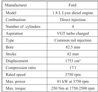
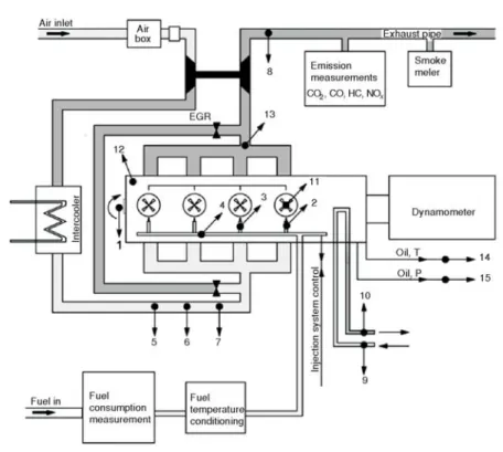
In this study, experiments were per-formed on a Ford 1.8 L, CI diesel engine using conventional diesel fuel. The test engine specifications are given in tab. 1. The instrumentation specifications used on the test bench are shown in tab. 2. The schematic picture of the test set-up is shown in fig. 1.
The experiments were run at maxi-mum engine torque speeds (2000 rpm, 2500 rpm) and maximum engine power speed (3750 rpm). The intake manifold pressure was kept constant during the tests using variable geometry turbo con-trol. Before starting the main experi-ments, the pre-experiments were per-formed to identify the engine’s behav-iour. The injected fuel mass was con-trolled by the engine control unit (ECU). The mass of fuel injected for
each cycle is defined by considering the mechanical limits of the engine, such as the maximum cylinder pressure and the turbo compressor outlet temperature. For each test point, three differ-ent injection pressures were tested.
Table 2. Test bench instrumentation
Instrumentation Type Sensitivity
Dynamometer AVL APA 204/8 ±0.3%
Fuel flow AVL 735C ±0.12%
Fuel temperature control AVL 735S ±1 °C
Air flow ABB sensy flow-P ±0.9%
Emissions
CO, HC, CO2, NOx Horiba mexa 7100 DEGR ±1.0%
Soot AVL 415S ±0.1%
Test automation system AVL Puma open 1.4 ISAC400 –
ECU Siemens l200 –
ECU control, [19] ATI vision 3.5 software [3] – Table 1. Test engine specifications
Manufacturer Ford
Model 1.8 L Lynx diesel engine Combustion Direct injection Number of cylinders 4 Aspiration VGT turbo charged Type Common rail injection
Bore 82.5 mm Stroke 82 mm Displacement 1753 cm³ Compression ratio 17/1 Rated speed 3750 rpm Max. power 81 kW at 3750 rpm Max. torque 250 Nm at 1750-2500 rpm
Test procedure and test points
In this study, engine speeds of 2000, 2500, and 3750 rpm were investigated. For each engine speed, three different fuel masses were injected. Only one injection strategy was pursued. No pi-lot or post injection was uti-lised. During the tests, the SOI and rail pressure were varied and the intake mani-fold pressure was kept con-stant within the predefined range, which was identified with two pre-tests.
EGR was not employed. In total, 108 experiments were performed on the test bench. The tested points are Figure 1. Experimental set-up
Table 3. Test points Test point [rpm] Mass of injection per cycle [mg per stroke] Intake manifold pressure [hPa] Rail pressure variation [MPa] SOI variation [°CA] (aTDC*) 2000 25 2000 120, 130, 140 –15, –10, –5,0 38 2200 130, 140, 150 43 2300 130, 140, 150 2500 28 2000 130, 140, 150 37 2200 130, 140, 150 45 2300 130, 140, 150 3750 25 2000 120, 130, 140 38 2200 130, 140, 150 40 2300 130, 140, 150
listed in tab. 3. To make a steady-state analysis, the engine was warmed up to 90 °C before the experiments. Then, the engine speed and load were set to the desired values. Each measurement point had a stabilising time of 2 minutes and a recording time of 140 seconds.
Artificial neural network design
Haykin [10] stated, “ANN is a massively parallel-distributed processor, made up of inter-connected simple processing units, which has a natural propensity to store experiential in-formation and to make it available for use. It resembles the brain in two respects: (1) Knowledge is acquired by the network from its environment through a learning process; (2) Interneuron strengths, known as synaptic weights, are used to store the knowledge.”
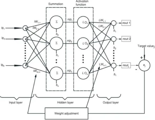
The ANN methodology has different network types that researchers use for solving various problems. The MLP network is a feed-forward ANN that can map a set of input data to a set of appropriate outputs. MLP are particularly developed for the solution of non-linear behav-ioural problems. The MLP structure is mainly formed from three layers as shown in fig. 2. These layers are: (a) input layer – consisting of the input parameters, and these parameters are consid-ered as they affect the outputs of the network, (b) hidden layer – the inputs are processed within the weights and biases with the predefined non-linear activation functions, and (c) output layer – consisting of the output parameters. The MLP working process includes three consecutive steps: (1) creating and configuring the network – the inputs, number of hidden layers, number of neurons at the hidden layer, activation function and the topology of the network is identified at this step, (2) training the network – initialise the weights and biases, and error minimisation with respect to targeting the data, and (3) usage of the network. At the beginning of the MLP process, each input is multiplied with an appropriate weightw; generally thiswis identified arbitrarily at the initialisation step. We can call this result of multiplication the weighted inputs (wi), and the weights at this input layer are called input weights (iw):
wi iw ip n n n = å n =1( min. ) (1) wheremis the number of inputs andn– the number of neurons at the hidden layer. Then, these weighted inputs are summed with biasesb, where bis the threshold value. The result is called the “net input –nip”.
nipn =win +bn (2)
Then, the net input is passed through a transfer function, which has to be differentiable (generally sigmoid) and produces the output (o):
o nipn n e = + -1 1 (3)
After the output is calculated, the outputs are multiplied with the layer weights (LW) and summed with biases. The result is called net output (nout):
n j LW onj n b n n out = + =
å
( 1) 1 (4) This step is called the feed forward calculation. After the output of the network is ob-tained, the desired jthoutput is compared with the desiredjth target value (t) and the error (e) is calculated:In the following step, to minimise the error, the error value is distributed to the weights with a predefined algorithm where the performance of the ANN is evaluated with the MSE algo-rithm: MSE j j ej = æå è ç ö ø ÷ 1 2 (6) These two steps have to be repeated until the desired predefined error level is reached. These two consecutive steps can be generalised as the “training step” of an MLP-type ANN [9, 20, 21]. For training, any standard numerical optimisation algorithm can be used to optimise the performance function. Bealeet al. stated [21], “there are a few key ones that have shown excel-lent performance for neural network training in which these optimisation methods use either the gradient of the network performance with respect to the network weights or the Jacobian of the network errors with respect to the weights. The gradient and the Jacobian are calculated using a technique called the back propagation algorithm, which involves performing computations backward through the network.” When the error reaches a previously determined tolerance value, the training process is stopped [11]. According to Oztemel [20] “the information that is produced during this process is measured and stored within these adjusted weights and it is hard to reveal and interpret this information. “During these processes, the ANN learns the underlying function/physics of the system, while the results of the ANN learning are adjusted weights that could be used to accurately approximate the underlying function/physics of the system [7]. After the learning step, the network is tested with a different data set than that which was actualised before, and the performance of the network is analysed [20]. The structure of ANN is shown in fig. 2.
Application of neural networks
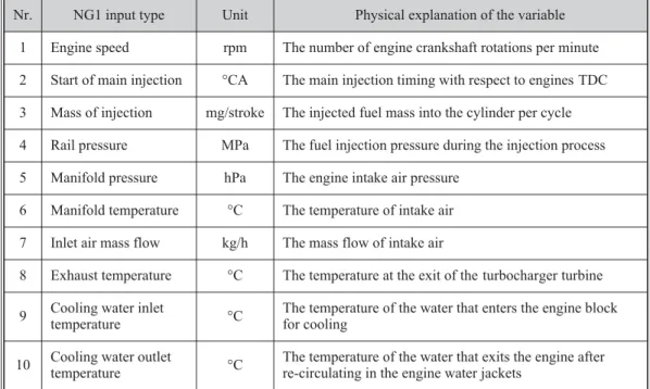
The goal of using ANN for this work is estimating the desired engine output parameter by using some engine operating parameters as inputs for the designed neural network. The net-work groups studied in this net-work were divided into two main groups. The first netnet-work group (NG1) used 10 engine operating parameters as inputs at the input layer of the network. These in-puts are listed in tab. 4. All NG1 inin-puts are indicated in fig. 1 with respect to their numbers (Nr). Each network is trained for estimating only one individual engine output parameter. This input group will be called the standard input package (SIP) after this point. The outputs are brake power [kW], BSFC , [gkW–1h–1]brake torque [Nm] and brake-specific engine out emissions, which are CO2[gkW–1h–1], CO [gkW–1h–1], THC [gkW–1h–1], NO
x[gkW–1h–1], and filter smoke number (FSN). This first group of networks has only one hidden layer, and during the training sessions, the neuron number of the hidden layer was increased from 1 to 20 to investigate the re-action of the network output to the hidden layer neuron number.
Table 4. Standard input package inputs
Nr. NG1 input type Unit Physical explanation of the variable 1 Engine speed rpm The number of engine crankshaft rotations per minute 2 Start of main injection °CA The main injection timing with respect to engines TDC 3 Mass of injection mg/stroke The injected fuel mass into the cylinder per cycle 4 Rail pressure MPa The fuel injection pressure during the injection process 5 Manifold pressure hPa The engine intake air pressure
6 Manifold temperature °C The temperature of intake air 7 Inlet air mass flow kg/h The mass flow of intake air
8 Exhaust temperature °C The temperature at the exit of the turbocharger turbine 9 Cooling water inlet
temperature °C
The temperature of the water that enters the engine block for cooling
10 Cooling water outlet
temperature °C
The temperature of the water that exits the engine after re-circulating in the engine water jackets
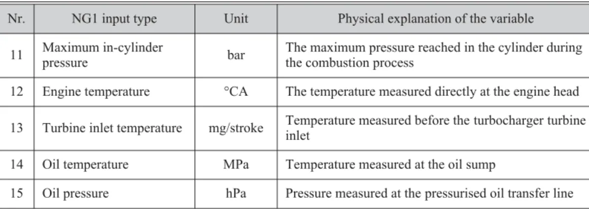
After the design, training and analyses of the NG1 network, the THC estimation re-sults were found to be unsatisfactory, and a new group (NG2) of networks were created to pre-dict the THC. While designing the new individual networks for THC formation, the characteris-tics of this pollutant were considered. HC are the consequence of incomplete combustion, and HC emissions are sensitive to the oil and coolant temperature and increase from fuel absorbed in deposits and oil layers [22, 23. Therefore, in the newly designed networks, the parameters that were related to enhancing the phenomenon of HC oxidation and HC absorption at the oil layers were considered. All of the new parameters are listed in tab. 5.
Table 5. Additional NG2 inputs and physical explanations
Nr. NG1 input type Unit Physical explanation of the variable 11 Maximum in-cylinder
pressure bar
The maximum pressure reached in the cylinder during the combustion process
12 Engine temperature °CA The temperature measured directly at the engine head 13 Turbine inlet temperature mg/stroke Temperature measured before the turbocharger turbine
inlet
14 Oil temperature MPa Temperature measured at the oil sump
15 Oil pressure hPa Pressure measured at the pressurised oil transfer line
The first group of new parameters that can be correlated with HC oxidation consisted of the maximum in-cylinder pressure, engine temperature, and turbine inlet temperature. The tur-bine inlet temperature is measured directly from the plenum of the exhaust manifold (before the turbocharger turbine section inlet). These data reflect more precise information about the com-bustion process and the comcom-bustion temperature than the exhaust temperature that was taken from the exhaust line (after the exit of turbocharger turbine) and more directly affect the HC oxi-dation. The second group of new parameters consisted of the oil temperature and oil pressure, which can be correlated with oil absorption at the deposits and oil layers. Each NG2 input is in-dicated in fig. 1 relative to their numbers. The NG2, which has three subgroups, uses the afore-mentioned operating parameters in addition to the SIP to estimate the THC. The first subgroup of NG2 (NG21) has three parameters, and the second subgroup of NG2 (NG22) has two extra in-put parameters in addition to the SIP. The third subgroup of NG2 (NG23) uses these extra five parameters, which were used in NG21 and NG21, in addition to the SIP. The NG2 input parame-ters groups are listed in tab. 6. The main aim of creating new networks is develop a satisfactory THC estimation. During this process, the reaction of the network to the increased number of in-put parameters and to the inin-put type was also investigated.
Table 6. NG2 networks inputs Network
name Input parameters Output
NG21 SIP +Pmax*+ Engine temperature + Turbine inlet temperature
THC NG22 SIP + Oil temperature + Oil pressure
NG23 SIP +Pmax+ Engine temperature + Turbine inlet temperature + Oil temperature + + Oil pressure
* Pmax– maximum in-cylinder pressure
The data group obtained in the experiments was composed of 108 data sets, and these data sets were divided into three subsets. The first subset was the training set, which was used to compute the gradient and update the network weights and biases. This first subset included 50% of the experimental data. The second subset was the validation set, which included 20% of the
experimental data. The error in the validation set was monitored during the training process. The validation error was expected to decrease during the initial phase of training, as did the training set error. However, when the network began to over-fit the data, the error on the validation set began to rise. Training continued until the validation error failed to decrease for six iterations. Then, the weights and biases at the minimum validation error were recorded and used. The third subset was the test set through which the network performance can be checked separately. The test set consisted of 30% of the experimental data set. The Matlab Programme ANN toolbox was used for developing and analysing the networks. A two-layer feed forward network with a tan-gent sigmoid (tansig) transfer function at the hidden layer and a linear transfer function at the output layer was formed for output estimation. In this study, the Levenberg-Marquardt algo-rithm was used for training, validation and testing that used the Jacobian of the network errors. The algorithm used is shown below:
H = JTJ (7)
g = JTe (8)
xk+1= xk–[JTJ +mI]–1JTe (9) where,H is the Hessian matrix approximation,J– the Jacobian matrix that contains first deriva-tives of the network errors,m– the Levenberg damping factor,k– the iteration number or the time step,x– the value of the weights, ande– the vector of network errors. This algorithm is the fastest method for training moderate-sized feed forward neural networks up to several hundred weights [21]. Extensive information about the Levenberg-Marquardt algorithm can be found in the literature [24]. The correlation coefficients (R) for the learning, validation, and testing stages were calculated to evaluate the ANN prediction capabilities. Additionally, the MSE obtained were provided for these stages [8, 21, 25]:
R t t nout nout t t nout nout j j j j j j j j = å - -å -= = ( ) ( ) ( ) ( ) 1 2 1 2 j j = å 1 (10)
wheretjis the target (real) value ofjthtest point output, thenout
j– the output of the network esti-mated value (Est.), andt andnoutare the mean values of the target and output values group, re-spectively.
Results and discussion
NG1 networks
The NG1 network overall regression (R) with an increasing neuron number at the hidden layer is given in fig. 3 for the CO, CO2, NOx,
and FSN brake emissions, brake torque, brake power, and BSFC. The regression values pre-sented in the figures are the values of the entire process (the combined training, validation, and testing phases). As seen from the figures and trend lines, the regression/performance of the
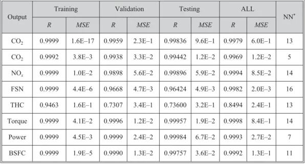
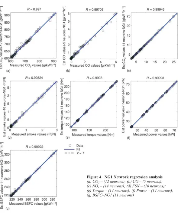
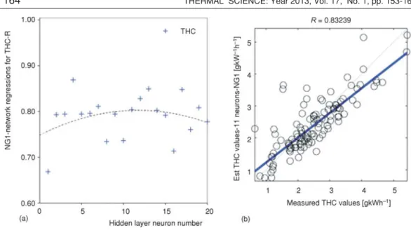
number, and the average regression is over ~95%, which is a satisfactory result for this research. The neuron number of NG1 networks that show estimation performance superior to the others are: 13 neurons for CO2estimation, 5 neurons for CO estimation, 14 neurons for NOxestimation, a 16 neurons for FSN estimation, 14 neurons for torque, 7 neurons for power estimation, and 11 neurons for BSFC estimation. TheRandMSEvalues are shown in tab. 7. The performance graphs for the networks with the best regression are shown in fig. 4 (a-g). The THC estimation results for the NG1 networks and the best estimator network for the THC from NG1 group (13 neuron network, R-0.84945 and 0.24 MSE) and its performance graph are shown in fig. 5. As shown in the figure, the average estimation performance for THC is ~75, which is not satisfac-tory. Then, the new network group, which will be called the NG2 networks, were designed for THC estimation.
Table 7. Best NG1 networksRandMSEvalues Output
Training Validation Testing ALL
NN*
R MSE R MSE R MSE R MSE
CO2 0.9999 1.6E–17 0.9959 2.3E–1 0.99836 9.6E–1 0.9979 6.0E–1 13 CO2 0.9992 3.8E–3 0.9938 3.3E–2 0.99442 1.2E–2 0.9969 1.2E–2 5 NOx 0.9999 1.0E–2 0.9898 5.6E–2 0.99896 5.9E–2 0.9994 8.5E–2 14
FSN 0.9999 4.4E–6 0.9668 4.7E–3 0.96424 4.9E–3 0.9982 2.0E–3 16 THC 0.9463 1.6E–1 0.7307 3.4E–1 0.73600 3.2E–1 0.8494 2.4E–1 13 Torque 0.9999 4.1E–2 0.9996 1.2E–2 0.99957 1.9E–2 0.9998 8.4E–1 14 Power 0.9999 4.5E–3 0.9999 2.4E–2 0.99984 6.7E–2 0.9993 2.7E–2 7 BSFC 0.9999 1.9E–5 0.9990 1.3E–2 0.99757 3.6E–2 0.9992 1.3E–1 11
* NN – number of neutrons at hidden layer NG2 networks
The NG2 networks were solely designed for THC estimation. The main aim is a better estimation of THC with an increased number of inputs and also increased prior knowledge. The three new network group performances and the reference NG1 network performances with the increasing neuron numbers are given in fig. 6. As shown in the indicated trend lines for the data sets, the estimation performance increased with an increasing number of inputs for the THC emissions. Whereas the NG1 reference performance, with the SIP input packet, remained at ap-proximately 75%, the NG21 performance with its input packet of engine temperature, turbo tur-bine inlet temperature and the current SIP packet was approximately 80%. The NG22 perfor-mance with its input packet of oil temperature, oil pressure and the standard SIP packet was ~85%, and the NG23 performance with its input packet of engine temperature, turbine inlet tem-perature, oil temtem-perature, oil pressure, and the standard SIP packet was ~90%. It is obvious that the NG22 network estimation performance (~85%) is higher than NG21 (~80%). Therefore, the
networks for this experiment are more sensitive to the oil temperature and oil pressure data char-acteristics for THC estimation. The neuron numbers for the NG2 networks with superior esti-mation performance are: 11 neurons for the NG21 network, 10 neurons for the NG22 network, and 11 neurons for NG23. TheRandMSEvalues are given in tab. 8. The performance graphs for these networks are given in fig. 7(a-c).
Figure 4. NG1 Network regression analysis (a) CO2– (12 neurons); (b) CO – (5 neurons); (c) NOx– (14 neurons); (d) FSN – (16 neurons); (e) Torque – (14 neurons); (f) Power – (14 neurons); (g) BSFC–NG1 (11 neurons)
Table 8. Best NG2 networksRandMSEvalues NG2
Network
Training Validation Testing All
NN
R MSE R MSE R MSE R MSE
NG21 0.9867 2.0E–2 0.7011 4.2E–1 0.8383 2.7E–1 0.8819 1.7E–1 11 NG22 0.9956 7.8E–2 0.8301 2.9E–1 0.9265 2.3E–1 0.9292 1.3E–1 10 NG23 0.9975 4.4E–3 0.775 3.2E–1 0.8839 2.4E–2 0.9155 1.3E–1 11 Figure 5. ( a) NG1 network regressions for THC; (b) Regression analysis of THC– NG1(11 neurons)
Conclusions
In this study, the performance of the neural network calculation method was investi-gated to estimate two engine-out parameters. A regression analysis between the network re-sponse and the corresponding targets was performed. The results indicate the following.
· The estimation performance of neural networks increased with an increasing neuron number at the hidden layer in all cases.
· The NOx, CO, CO2, power, torque, and specific fuel consumption estimations are satisfactory (over 95%) using the SIP as the input layer of the neural network.
· An increased number of inputs at the input layer results in increased estimation performance (75% to 90%) for the THC estimations.
· For the same number of inputs, NG22 networks are more sensitive than the NG21 networks for THC estimation, which use only oil pressure and oil temperature at the input layer instead of engine temperature and turbo turbine inlet temperature.
· The overall performance of neural networks is satisfactory, and it is obvious that with the proper input layer and hidden layer characterisation, this method can be utilised to estimate the engine out parameters with high levels of confidence.
References
[1] ***, ACEA, EU Economic Report, in, European Automobile Manufacturers’ Association, Brussels, 2010 [2] ***, ACEA, Europan Vehicle Fleet, in, European Automobile Manufacturers’ Association, Brussels,
2010
[3] Bargezar, R.,et al., CFD Simulatýon of the Combustion Process, Emission Formation and the Flow Field in an In-Direct Injection Diesel Engine,Thermal Science 17(2013), 1, pp. 11-23 (in this issue)
[4] Sudeshkumar, M. P., Devaradjane, G., Development of a Simulation Model for Compression Ignition En-gine Running with Ignition Improved Blend,Thermal Science, 15(2011), 4, pp. 1131-1144
[5] Moldovanu, D., Burnete, D., CFD Simulation of a Single Cylinder Research Engine Working with biodiesel,Thermal Science, 17(2013), 1, pp. 195-203
[6] Ganapathy T.,et al., Artificial Neural Network Modeling of Jatropha Oil Fueled Diesel Engine for Emis-sion Predictions,Thermal Science, 13(2009), 1, pp. 91-102
[7] He, Y., Rutland, C. J., Application of Artificial Neural Networks in Engine Modeling,International Jour-nal of Engine Research, 5(2004), 4, pp. 281-296
[8] Zhou, H.,et al., Modeling and Optimization of the NOxEmission Characteristics of a Tangentially Fired Boiler with Artificial Neural Networks,Energy, 29(2004), 1, pp. 167-183
Figure 7. (a) Regression analysis of THC–NG21 network (14 neurons); (b) Regression analysis of THC–NG22 network (10 neurons); and (c) Regression analysis of THC–NG23 network (11 neurons)
[9] Karonis, D.,et al., A Neural Network Approach for the Correlation of Exhaust Emissions from a Diesel Engine with Diesel Fuel Properties,Energy & Fuels, 17(2003), 5, pp. 1259-1265
[10] Haykin, S., Neural Networks: A Comprehensive Foundation, Prentice Hall, New York, USA, 1998 [11] Oguz, H.,et al., Prediction of Diesel Engine Performance Using Biofuels with Artificial Neural Network,
Expert Systems with Applications, 37(2010), 9, pp. 6579-6586
[12] Moskwa, J. J., Chen, S. X., Dynamic Engine Modeling for Diagnostics and Simulation., Inc. PPT Group, 1995
[13] Munns, S. A., Computer Simulation of Power Train Components with Methodologies for Generalized System Modeling., Department of Mechanical Engineering, University of Wisconsin-Madison, Wis., USA, 1996
[14] Uzun, A., A Parametric Study for Specific Fuel Consumption of an Intercooled Diesel Engine Using a Neural Network,Fuel, 93(2012), March, pp. 189-199
[15] Yuanwang, D.,et al., An Analysis for Effect of Cetane Number on Exhaust Emissions from Engine with the Neural Network,Fuel, 81(2002), 15, pp. 1963-1970
[16] de Lucas, A.,et al., Modeling Diesel Particulate Emissions with Neural Networks,Fuel, 80(2001), 4, pp. 539-548
[17] Canakci, M.,et al., Prediction of Performance and Exhaust Emissions of a Diesel Engine Fueled with Biodiesel Produced from Waste Frying Palm Oil,Expert Systems with Applications, 36(2009), 5, pp. 9268-9280
[18] Parlak, A.,et al., Application of Artificial Neural Network to Predict Specific Fuel Consumption and Ex-haust Temperature for a Diesel Engine,Applied Thermal Engineering, 26(2006), 8-9, pp. 824-828 [19] ***, ATI Vision, www.accuratetechnologies.com/content/view/240/237/lang.en/, 2012
[20] Oztemel, E., Artificial Neural Networks, Papatya Publishing, Istanbul, Turkey, 2003
[21] Beale, H. M.,et al., Matlab Neural Network Toolbox User Guide, The Mathworks Inc., Natick, Mass., USA, 2010
[22] Heywood, J., Internal Combustion Engine Fundamentals, McGraw-Hill, New York, USA, 1988 [23] Borman, L. G., Ragland, K. W., Combustion Engineering, McGraw-Hill Book Co., New York, USA, 1998 [24] Hagan, M. T.,et al., Neural Network Design PWS Pub. Co., Boston, Mass., USA, 1995
[25] Manjunatha, R.,et al., Application of Artificial Neural Networks for Emission Modelling of Biodiesels for a CI Engine under Varying Operating Conditions,Modern Applied Science, 4(2010), 3, pp. 77-89
Paper submitted: March 21, 2012 Paper revised: September 14, 2012 Paper accepted: September 22, 2012