A Heuristic Optimization Technique for the
Design of Band Stop FIR Digital Filter
Dilpreet Kaur
1, Balraj Singh
2, Darshan Singh Sidhu
3M.Tech (Scholar), Department of Electronics and Communication Engineering (ECE), Giani Zail Singh Campus
College of Engineering and Technology, Bathinda, Punjab, India1
Associate Professor, Department of Electronics and Communication Engineering (ECE), Giani Zail Singh Campus
College of Engineering and Technology Bathinda, Punjab, India2 Principal, Government Polytechnic College, Bathinda, Punjab, India3
ABSTRACT: This paper focuses at designing an optimal Band Stop FIR digital filter by using Predator Prey Optimization (PPO) technique. PPO is stochastic population based technique that explores the search space locally as well as globally. PPO is a mere extension of Particle Swarm Optimization (PSO), in which the new particle known as Predator; produces diversity in the swarm population and avoid convergence to sub-optimal solutions. Opposition based strategy has been employed in order to obtain better solutions. PPO provides a comprehensive set of results and outperforms the traditional optimization techniques. Effectiveness of PPO has been proved by carrying out the comparison between the obtained results and results of Differential Evolution.
KEYWORDS: FIR digital filter, Predator Prey Optimization, Differential Evolution, Passband Ripples ( ) , Stop Band Ripples ( ).
I. INTRODUCTION
Filtering is an aspect of signal processing that provides partial or complete suppression of undesirable features of a signal and this task is performed by a device known as Filter. A filter neither adds nor removes any frequency component of a signal; it just changes the phase or amplitude characteristic of signal with respect to frequency. It extracts only desired portion of a signal with no or less background noise under the prescribed frequency range. Basically filters are of two types: Analog Filter and Digital Filter. Digital filter processes the discrete-time signals and has many advantages over an analog filter like digital filter provides higher accuracy and involves smaller physical size. Digital filters are much in use these days because it offers flexibility and programmable operations. Digital filters are capable of performing all the complex tasks that were initially performed by analog filters hence; it has replaced the conventional analog filters in the fields of radar processing, speech and signal processing and biomedical [7, 5].
Window method is the most common and an effective method of designing a FIR digital filter. A window is an array of coefficients that are selected in order to meet the desired requirements. A specific window function truncates the impulse response of an ideal filter. Window method provides simple operation and is a very convenient designing method. The obtained impulse response coefficients are in closed form and can be determined easily. The certain disadvantages of window method are that it provides wider main lobes, involves higher computational complexity and does not ensure a proper control of the frequency spectrum parameters [9].
Therefore, Evolutionary optimization techniques are preferred for the designing of an optimal FIR filter. Different evolutionary optimization techniques available are Ant Bee Colony, Genetic Algorithm, Particle Swarm Optimization, Differential Evolution and Predator Prey Optimization. This paper aims at using Predator Prey Optimization for the design of a Band Stop FIR digital filter. This paper has been structured in five sections. Related work has been discussed in Section II. Section III outlines the FIR digital filter design problem. The proposed algorithm has been discussed in Section IV. The performance of PPO has been evaluated and comparison of the obtained results with DE [12] has been carried out in Section V. Section VI contains the obtained conclusion.
II. RELATED WORK
Genetic Algorithm (GA) is a population based optimization technique. In GA, the evolution of population takes place through an iterative process. Random selection of best individuals is done on the basis of fitness of each individual. Then recombination and mutation is done in order to develop new chromosomes. The fitness of these newly generated chromosomes is evolved. At last, old population is replaced by the new population and this process is repeated until optimal solutions are obtained. GA provides better magnitude and phase response with minimum phase delay. But GA offers slower convergence and also perform only local search [4].
Differential Evolution (DE) was proposed by Price and Storn in 1995. DE is a population based global search optimization technique. The new chromosomes are generated by using a differential operator rather than through conventional method of crossover and mutation. It works efficiently with non-differentiable continuous and real-valued functions. DE provides faster convergence, better solution quality, least run time in comparison to classical optimization techniques [3].
Particle Swarm Optimization (PSO) is another population based stochastic global search technique. PSO works well with differential functions and provides fast computation. By controlling fewer parameters PSO ensures better convergence rate. Premature convergence and local stagnation are the two major limitations of PSO. PSO may trap into local optimum solutions and sometimes may also losses its ability to search the N-dimensional space globally [1, 10]. To overcome these limitations of PSO, Predator Prey Optimization technique has been proposed by Silva et.al. Predator in PPO introduces diversification in the swarm population resulting into global search of optimal solutions. PPO can be used in data clustering applications as it always keeps the particles in motion. PPO can be used in multidimensional search spaces [2, 6].
III. FIR FILTER DESIGN PROBLEM
Finite Impulse Response filter is a recursive filter as its output depends only on past, present and future values of input. Impulse response a FIR filter has only finite number of terms and it approaches to zero in finite time. FIR filter is characterised by Equ. 1:
1 0 ) ( ) ( M k k m x b k m
y (1)
wherex(m) represents the filter input, y(m)
represents the filter output,,
b k is the set of filter coefficients and the filter order is given by M. Equ.2 represents the transfer function for FIR filter: M n z n n h z H 0 ) ( )
) (z
H is frequency domain impulse response,h(n) is time domain impulse response and Mis filter order. The number of filter coefficients and the length of filter is M1 i.e. one more than the filter order. Due to symmetrical nature of FIR filter, only half of the filter coefficients are to be calculated and the remaining + 1 coefficients can be obtained through the calculated + 1 coefficients.
An even symmetric band stop FIR digital filter has been designed in this paper. The ideal response of the band stop FIR digital filter is given by Equ. 3:
( ) = 0 ≤ ≤
1 ℎ (3) and are the cut off frequencies. The performance of band stop FIR digital filter is evaluated by minimizing the value of four design parameters that are L1-norm and L2-norm approximation error of magnitude response and magnitude of ripples of both passband and stopband.
L1-norm error (for p=1) is given by Equ. 4:
k
i d i i
x
H
w
H
w
x
e
0 )
(
(
)
(
,
)
1 1
1 (4)
L2-norm error (for p=2) is given by Equ. 6:
k
i d i i
x
H
w
H
w
x
e
0
2 )
(
(
)
(
,
)
2 1
2
(5)
where ( ) is the desired magnitude response of an ideal FIR filter and ( , ) is the obtained magnitude response for a given set of filter coefficients.
The magnitude response for ideal FIR filter is required to be 1 in the passband and 0 in the stopband. The desired magnitude response is given by Equ. 6:
( ) = 0 1 ∈ ∈ (6)
The ripple magnitude for passband and stopband is given by Equ.7 and Equ. 8:
( ) = {| ( , )|}− {| ( , )|}; ∈ (7)
( ) = {| ( , )|}; ∈ (8) Passband ripples and stopband ripples are represented as ( ) and ( ) respectively.
The four objective functions that are to be optimized are defined as:
( ) = ( )
( ) = ( )
All these four objective functions are converted into single objective function given by Equ. 9:
( ) = ( ) + ( ) + ( ) + ( ) (9)
where , , , are the weighting functions. Equ.9 represents the overall objective function that has to be minimized in order to obtain an efficient Band Stop FIR digital filter by using the proposed PPO algorithm.
IV. PREDATOR PREY OPTIMIZATION
Predator prey optimization is an efficient population based global search technique. PPO explores the search space both locally as well as globally resulting into optimal solutions. PPO is basically a nature inspired optimization technique that is based on the behaviour of birds searching for their food. Like PSO, in PPO there are prey particles that search for their best position and a best individual is selected on the basis of fitness. In order avoid local stagnation and premature convergence a new particle called Predator is introduced in PPO. The behaviour of prey and predator is different from each other. Predator always runs after the prey particles, it gets attracted to the best individual. With the fear of predator the prey particles searches for the global best position. In this way, predator introduces diversification in swarm population.
The balance between exploration and exploitation is maintained by the diversity introduced by predator. By controlling the frequency and strength of the interactions between prey particles and a predator; the balance between local and global search can be maintained. Predator fear represents the probability that the prey particles will change their velocity in one of the available N-dimensions. Whenever the value of predator fear is greater than the maximum predator fear the velocity and position of prey particles are updated with predator affect [2, 6].
In evolutionary optimization techniques efforts are made to obtain the optimal solutions. The searching process starts with random initialization whenever there is no prior information available and ends when certain prescribed criterion is satisfied. It may take large computation time to get the optimal solutions from these random initial guesses. Therefore, Opposition based learning proposed by Tizhoosh is used that saves the computation time. In Opposition based strategy the estimate and the opposite estimate are simultaneously evaluated. Either the estimate or its opposite estimate is selected as the initial value resulting into increased convergence speed. This strategy is applied to each solution for generating new population so as to start with best population [11]. Equ.10 represents the opposition based strategy:
, = + − ( = 1,2, … … … , ; = 1,2, … . , ) (10)
where and represents the lower and upper limits of filter coefficients.
Initialization of Position and Velocity of Prey and Predator
Positions of predator and prey particles have been randomly initialized within their upper and lower limits.
= + − = 1,2, … . . ; = 1,2, … . . (11) = + − ( = 1,2, … . ) (12)
where is number of prey particles. and are the random numbers and their value lies between 0 and 1. and are the range of decision variables.
Velocities of prey ( ) and predator ( ) have been selected as the design variables and have been initialized within their predefined limits.
= + − = 1,2, … . ; = 1,2, … … (13) = + − ( = 1,2, … ) (14)
=− − ( = 1,2, … … ) (15) = + − ( = 1,2, … . . ) (16) The value of is 0.25. Maximum and minimum value of velocities of prey particles can be achieved by varying the value .
Evaluation of Predator Velocity and Position
The position and velocity of predator are updated at the end of each iteration according to Equ. 17 and Equ. 18:
= ( − ) ( = 1,2, … . ) (17) = + ( = 1,2, … … . ) (18)
where is the global best position of prey and is a random number and its value lies between 0 and its upper limit.
Evaluation of Position and Velocity of Prey
At the end of each iteration, the velocity and position of prey particles are updated by using Equ. 19 and Equ. 20:
= + ( − ) + ( − ) ; ≤
+ ( − ) + ( − ) + ( ) ; >
(i=1,2,....,S; k=1,2,..., ) (19) = + (i=1,2,...,S; k=1,2,..., ) (i=1,2,...S ;k=1,2,... ) (20)
and represents the acceleration constants. is the local best position and is the global best position of prey. , and are the random numbers having value between 0 and 1. The exponential term ( ) represents the predator affect which increases with proximity. Whenever prey and predator come closer, this exponential term introduces disturbance in the swarm population. a is a measure of maximum amplitude of predator affect over prey. b represents the distance at which predator affect is significant. is the Euclidean distance between the prey and predator position.
= ∑ ( − ) (21)
w is an inertia parameter. By decreasing the value of the rate of convergence can be accelerated.
= [ −( − )( )] (22)
The constriction factor is defined by Equ. 23:
= 2− − −4 ≥4
1 < 4 (23) Violation of the prescribed limits of position and velocity of prey particles may take place. This violation can be
controlled by Equ. 24:
=
+ <
− >
;
Algorithm for Predator Prey Optimization
1. Initialize the PPO parameters i.e. population size ( ), acceleration constants ( , ), stopping criteria, maximum and minimum values of velocity and positions of prey particles ( ) and predator ( ) , maximum predator fear factor ( ).
2. Initialize the prey position and velocity. 3. Initialize the predator position and velocity. 4. Apply the opposition based strategy. 5. Calculate the objective function.
6. Select best preys from the total 2 preys.
7. Compute the personal best value for each particle and among the pbest values select the global best value. 8. Update velocity and position of predator by using Equ. 18 and Equ.19.
9. Randomly generate the predator fear factor between 0 and 1. 10. IF ( predator fear > maximum predator fear )
THEN
Position and velocity of prey particles are updated with predator affect. ELSE
Position and velocity of prey particles are updated without predator affect. ENDIF.
11. Again calculate the objective function.
12. Update local best positions of all the prey particles.
13. Compute the global best value of prey particles based on fitness. 14. IF (stopping criterion is satisfied)
THEN STOP ELSE
Go to step 8. ENDIF.
V. SIMULATION RESULTS
Simulation results have been performed in MATLAB. Designing of a Band Stop FIR digital filter has been carried by using Predator Prey Optimization technique. A Band Stop FIR digital filter has been designed by setting 200 equally
spaced points within the frequency domain [0, π]. Table 1 shows the design conditions for a Band Stop FIR digital filter.
Table 1: Design Conditions for Band Stop FIR Digital Filter
Filter Type Pass Band Stop Band Maximum Value of H(w, x)
Band Stop 00.25 0.75
0.4π≤ ≤0.6 1
Table 2: PPO Design Parameters
Sr. No. Parameter Value
1 Iterations 200
2 , 2.0
3 0.4
4 0.1
5 Population Size ( ) 100
6 0.7
7 1.0
8 10
9 10
Table 3: Achieved Value of Objective Function at Different Filter Orders of Band Stop FIR digital filter
Sr. No. Order of filter Objective function
1 18 3.692905
2 20 1.903845
3 22 1.915039
4 24 2.355752
5 26 0.988549
6 28 6.792734
7 30 12.81626
8 32 40.92289
Figure1: Order of filter versus Objective Function of Band Stop FIR digital filter
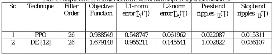
The comparison of obtained results with DE [12] has been carried out. Table 4 indicates that PPO provides better results than DE in terms of minimum value of performance parameters i.e. L1-norm error ( ), L2-norm error
( ), Passband ripples ( ), Stopband ripples ( ) ; signifying the effectiveness of PPO.
Table 4: Comparison of PPO results with DE results of Band Stop FIR digital filter at order 26 Sr. Technique Filter
Order
Objective Function
L1-norm error ( )
L2-norm error ( )
Passband ripples ( )
Stopband ripples ( )
1 PPO 26 0.988549 0.548747 0.061962 0.022087 0.015311 2 DE [12] 26 1.679148 0.955211 0.145541 1.002822 0.036107
0 20 40 60
18 20 22 24 26 28 30 32
O
b
je
c
ti
v
e
F
u
n
c
ti
o
n
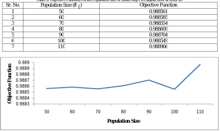
Now, parameter tuning has been done by varying the two control parameters: Population size ( ) and Acceleration constants ( , ). Population size has been varied from 50 to 110. Table 5 indicates the obtained objective function at different population size. Minimum objective function has been achieved at population size ( ) of 100.
Table 5: Objective Function versus Population size of Band Stop FIR digital filter at order 26 Sr. No. Population Size ( ) Objective Function
1 50 0.988561
2 60 0.988585
3 70 0.988554
4 80 0.988609
5 90 0.988704
6 100 0.988549
7 110 0.988966
Figure 2: Objective Function versus Population Size for Band Stop FIR digital filter at order 26
Acceleration constants ( , ) have been varied from 1.0 to 3.5 in steps of 0.5 as shown in Table 6. It is evident from the Fig. 3 that objective function has minimum value at and equal to 2.0.
Table 6: Objective Function versus Acceleration Constants ( , ) of Band Stop FIR digital filter at order 26 Sr. No. Acceleration Constants ( , ) Objective Function
1 1.0 1.021254
2 1.5 0.995485
3 2.0 0.988549
4 2.5 0.988739
5 3.0 0.989039
6 3.5 0.992911
0.9883 0.9884 0.9885 0.9886 0.9887 0.9888 0.9889 0.989
50 60 70 80 90 100 110
O
b
je
c
ti
v
e
F
u
n
c
ti
o
n
Figure 3: Objective Function versus Acceleration Constants of Band Stop FIR digital filter at order 26
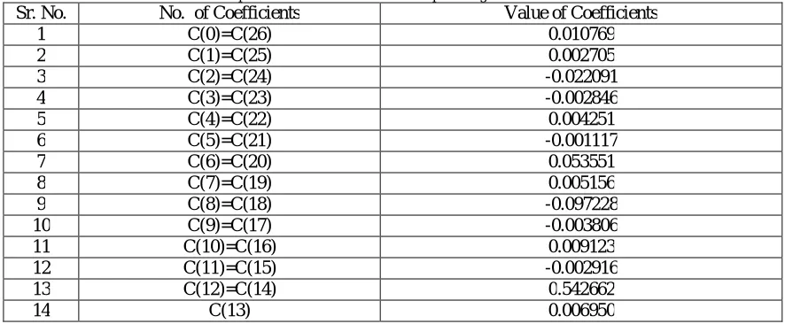
Thus, for the Band Stop FIR digital filter minimum objective function has been achieved at filter order 26, population size ( ) of 100 and acceleration constants ( , ) equal to 2.0. Table 7 points to the obtained optimized coefficients of Band Stop FIR digital filter at order 26.
Table 7: Optimized Coefficients of Band Stop FIR digital filter at Order 26 Sr. No. No. of Coefficients Value of Coefficients
1 C(0)=C(26) 0.010769
2 C(1)=C(25) 0.002705
3 C(2)=C(24) -0.022091
4 C(3)=C(23) -0.002846
5 C(4)=C(22) 0.004251
6 C(5)=C(21) -0.001117
7 C(6)=C(20) 0.053551
8 C(7)=C(19) 0.005156
9 C(8)=C(18) -0.097228
10 C(9)=C(17) -0.003806
11 C(10)=C(16) 0.009123
12 C(11)=C(15) -0.002916
13 C(12)=C(14) 0.542662
14 C(13) 0.006950
Afterwards, the magnitude response and phase response of the designed Band Stop FIR filter have been computed. Fig. 4 shows the graph between magnitude response and normalized frequency.
0.97 0.98 0.99 1 1.01 1.02 1.03
1 1.5 2 2.5 3 3.5
O
b
je
c
ti
v
e
F
u
n
c
ti
o
n
Figure 4: Magnitude response of Band Stop FIR digital filter at order 26
Fig. 5 indicates the magnitude response in db verses normalized frequency.
Figure 5: Magnitude response in db of Band Stop FIR digital filter at order 26
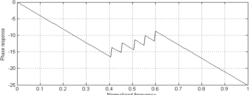
Graph for variation in phase with normalized frequency has been depicted in Fig.6.
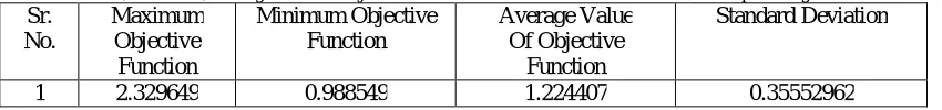
After the implementation of PPO algorithm for Band Stop FIR digital filter at order 26 the maximum, minimum and average values of objective function along with standard deviation have been computed. These values have been summarized in Table 8.
Table 8: Maximum, Minimum, Average value of Objective Function with Standard Deviation of Band Stop FIR digital filter at order 26 Sr.
No.
Maximum Objective Function
Minimum Objective Function
Average Value Of Objective
Function
Standard Deviation
1 2.329649 0.988549 1.224407 0.35552962
VI. CONCLUSION
This paper concentrates on the designing of Band Stop Finite Impulse Response digital filter by using Predator Prey Optimization technique. Simulation results have been executed in MATLAB. The objective function has been calculated at filter orders from 18 to 32 and minimum objective function has been obtained at filter order 26. Therefore, Band Stop FIR digital filter has been designed at filter order 26. The values of acceleration constants ( , ) and population size ( ) have been varied so to have more optimized filter coefficients. Minimum objective function has been obtained with population size ( ) of 100 and acceleration constants ( , ) equal to 2.0. The standard deviation of 0.35552962 has been achieved which less than 1 authenticating the robustness of the designed filter. Performance assessment of the obtained results has been carried out by doing comparison with DE [12]. Simulation results confirm that PPO is an efficient technique for designing the Band Stop FIR digital filter and PPO outperforms DE in terms of global search. Opposition based strategy has been employed that results into increased convergence speed. Similarly, PPO can be implemented for the designing of low pass; high pass and band pass FIR digital filters.
REFERENCES
[1] James Kennedy and Russell Eberhart,”Particle Swarm Optimization,” In Proceedings of IEEE International Conference Neural Network, Perth Australia, no. 4, pp. 1942-1948, 1995.
[2] Arlindo Silva, Ana Neves and Ernesto Costa,”Chasing The Swarm: A Predator-Prey Approach to Function Optimization”, Proceedings of MENDEL 2002-8th International Conference on Soft Computing, Brno Czech Republic, Czech Republic, 2002.
[3] S. Chattopadhyay, S.K Sanyal and A. Chandra ,” Design of FIR Filter using Differential Evolution on Optimization & to Study its Effect as a Pulse-Shaping Filter in a QPSK Modulated System”, International Journal of Computer Science and Network Security, vol. 10, no. 1, pp. 313-321, 2010.
[4] Pardeep Kaur and Simarpreet Kaur,”Optimization of FIR Filters Design using Genetic Algorithm”, International Journal of Emerging Trends & Technology in Computer Science, vol. 1, no. 3, pp. 228-232, 2012.
[5] John G.Proakis and Dimitris G. Manolakis ,”Digital Signal Processing”, Pearson Forth edition, 2013.
[6] Balraj Singh, J.S. Dhillon and Y.S. Brar ,”Predator Prey Optimization Method For The Design of IIR Filter”, WSEAS Transactions on Signal Processing, vol. 9, no. 2, pp. 51-62, 2013.
[7] Kamalpreet Kaur and J.S. Dhillon ,”Design of Digital IIR Filters using Integrated Cat Swarm Optimization and Differential Evolution”, International Journal of Computer Applications, vol. 99, no. 4, pp. 28-43, 2014.
[8] Neha Malhotra and Shikha Khanna ,”FIR Band Stop Filter optimization by Improved Particle Swarm Optimization”, International Journal of Computer Application, vol. 3,no. 4, pp. 94-99, 2014.
[9] Md. Saiful Islam, Md. Shariful Islam, Syed Khalid Rahman, Neelanjan Subin Ferdous and Jakeya Sultana Joyti ,” Design of FIR Filter using Hamming Window, International Journal of Engineering Research in Management & Technology, vol. 3, no.2, pp. 13-16, 2014.
[10] Jyoti Kumari and Deepak Nagaria,“Optimization of FIR Filter Parameters using Particle Swarm Optimization Technique”, International Journal of Scientific Engineering and Technology Research”, vol. 4, no. 1, pp. 99-101, 2015.
[11] Balraj J. Singh and J.S. Dhillon ,”Higher Order Optimal Stable Digital IIR Filter Design using Heuristic Optimization” Proceedings of Informing Science & IT Education Conference (InSITE), pp. 505-520, 2015.