IPFC Applied To Three Phase Four Wire
Distribution System Using Dual Control
N.Manonmani, Dr.G.Saravanan
M.E(PSE), Sona College of Technology, Salem, India
AP(Sr.Grade)/EEE, Sona College of Technology, , Salem, India
ABSTRACT: The IPFC (Interline Power Flow Controller) is among the FACTS devices aimed at simultaneously controlling the power flow in multiline systems. This paper presents the IPFC main features and limitations while controlling the power flow. In order to observe these advantages, a mathematical model based on the d-q orthogonal coordinates was developed. It is also used the real power being transferred between the compensated lines. For this purpose, 3 phase transmission line model associated with the converter station has been developed and incorporated in an IPFC model. Interline power flow controller have ability to make balance between multiple transmission line. The IPFC improve the power quality and managed power flow in the transmission line.
KEYWORDS: pspice, Filter, Microcontroller
I. INTRODUCTION
Nowadays the FACTS technologies are used for getting more service and enhance the reliability of the transmission facilities. There is necessary to utilize FACTS devices to improve the instability. The IPFC is capable to balance the power flow between multiple transmission lines. It has consisting no. of voltage source converter connected with the same DC terminals. Each voltage source converter provides series compensation to the individual line. In this way, the power optimization of the overall system can be realized through power transmit from overloaded lines to under loaded lines with dc link.
Fig 1. Basic structure of IPFC
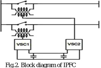
The IPFC consists of two voltage sourced converters, connected back-to-back and are operated from a common dc link provided by a storage capacitor as shown in the Fig.1.The functions as an ideal ac-to-ac power converter in which the real power can freely flow in either direction between the ac terminals of the two converters, and each converter can independently generate reactive power at its own ac output terminal. The interline power flow controller is one of the latest generation and advanced flexible AC transmission systems controller which can be used for dynamic compensation and effective power flow management among transmission corridors. It is VSC-based FACTS controller for Series compensation with the unique capability of power management among multiline of a substation. It simultaneously controls the power flow in multiline systems or sub network as shown in figure.2.
Since IPFC contain converters with common direct current link, any inverter within the IPFC is able to transfer real power to another and there by facilitate real power transfer among the lines of the transmission system. IPFC may be used to solve the complex transmission network overcrowding management problems that transmission companies are now a day facing to transmit a large power.
Fig.2. Block diagram of IPFC
Simplicity and fast system response are two main characteristics of Interline power flow controller.
II. PID CONTROL ALGORITHM
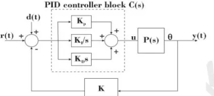
A PID controller is a common instrument used in industrial control applications. A PID controller can be used for regulation of speed, temperature, flow, pressure and other process variables. Field mounted PID controllers can be placed close to the sensor or the control regulation device and be monitored centrally using a SCADA system.In Fig 3 shows a block diagram of basic PID control algorithm.
of 5 would produce a proportional response of 50. In general, increasing the proportional gain will increase the speed of the control system response. However, if the proportional gain is too large, the process variable will begin to oscillate. If Kc is increased further, the oscillations will become larger and the system will become unstable and may even oscillate out of control.
Fig 3. Block diagram of basic PID control algorithm
The integral component sums the error term over time. The result is that even a small error term will cause the integral component to increase slowly. The integral response will continually increase over time unless the error is zero, so the effect is to drive the Steady-State error to zero. Steady-State error is the final difference between the process variable and set point. A phenomenon called integral windup results when integral action saturates a controller without the controller driving the error signal toward zero.
The derivative component causes the output to decrease if the process variable is increasing rapidly. The derivative response is proportional to the rate of change of the process variable. Increasing the derivative time (Td) parameter will cause the control system to react more strongly to changes in the error term and will increase the speed of the overall control system response. Most practical control systems use very small derivative time (Td), because the Derivative Response is highly sensitive to noise in the process variable signal. If the sensor feedback signal is noisy or if the control loop rate is too slow, the derivative response can make the control system unstable.
In a typical control system, the process variable is the system parameter that needs to be controlled, such as temperature (ºC), pressure (psi), or flow rate (liters/minute). A sensor is used to measure the process variable and provide feedback to the control system. The set point is the desired or command value for the process variable, such as 100 degrees Celsius in the case of a temperature control system. At any given moment, the difference between the process variable and the set point is used by the control system algorithm (compensator), to determine the desired actuator output to drive the system (plant). In Fig.4 shows a closed loop function of PID controller.
In many cases, the actuator output is not the only signal that has an effect on the system. For instance, in a temperature chamber there might be a source of cool air that sometimes blows into the chamber and disturbs the temperature. Such a term is referred to as disturbance. We usually try to design the control system to minimize the effect of disturbances on the process variable
2.1 Pulse width modulation:
The PWM switching frequency has to be much higher than what would affect the load (the device that uses the power), which is to say that the resultant waveform perceived by the load must be as smooth as possible. The rate (or frequency) at which the power supply must switch can vary greatly depending on load and application, for exampleSwitching has to be done several times a minute in an electric stove; 120 Hz in a lamp dimmer; between a few kilohertz (kHz) and tens of kHz for a motor drive; and well into the tens or hundreds of kHz in audio amplifiers and computer power supplies.The term duty cycle describes the proportion of 'on' time to the regular interval or 'period' of time; a low duty cycle corresponds to low power, because the power is off for most of the time. Duty cycle is expressed in percent, 100% being fully on.
2.2 Duty Cycle
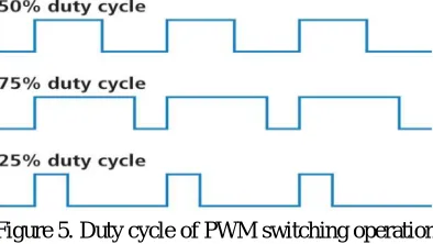
If a digital signal spends half of the time on and the other half off, we would say the digital signal has a duty cycle of 50% and resembles an ideal square wave. If the percentage is higher than 50%, the digital signal spends more time in the high state than the low state and vice versa if the duty cycle is less than 50%. Here is a graph that illustrates these three scenarios as shown in Fig.5.
Figure 5. Duty cycle of PWM switching operation
100% duty cycle would be the same as setting the voltage to 5 Volts (high). 0% duty cycle would be the same as grounding the signal.
2.3 Advantages
The main advantage of PWM is that power loss in the switching devices is very low. When a switch is off there is practically no current, and when it is on and power is being transferred to the load, there is almost no voltage drop across the switch. Power loss, being the product of voltage and current, is thus in both cases close to zero. PWM also works well with digital controls, which, because of their on/off nature, can easily set the needed duty cycle. PWM has also been used in certain communication systems where its duty cycle has been used to convey information over a communications channel.
III.INTERLINE POWER FLOW CONTROLLER (IPFC)
The IPFC structure makes it possible to transfer reactive power, as well as to exchange real power with the line. This active power can be obtained through power exchange through DC connection between the SSSCs in different lines. On the other hand, the transmitted powers in each line is a function of the voltage amplitude of sending and receiving buses, phase shift of sending and receiving buses and series impedance of the line.
Fig 6. Schematic diagram of two converters IPFC
The real power exchanged at the ac terminal is converted by the corresponding VSC into dc power which appears at the dc link as a negative or a positive demand. Consequently, the real power negotiated by each VSC must be equal to the real power negotiated by the other VSC through the dc lines. As result interline power flow controller (IPFC) can maintain the flow of active and reactive power in multiple line system even when a failure occur IPFC can switch off failure line and by bass to the set line.
3.1 Three phase four wire Inverter
Three-phase four-leg voltage source inverter operating in island mode is described. The four-leg inverter is implemented by using a delta/wye or ZigZag transformer to meet isolation requirement. The control scheme includes an inner current loop providing the capability of fast current limiting and outer voltage loop. Digital sliding mode control is used for the inner current loop which requires higher bandwidth. The voltage loop is implemented in synchronous frame with selected harmonics cancellation for both positive and negative sequence components. Simulation and test of a 125 kW inverter at various operation conditions are presented to verify the validity of the control method
A control technique is developed for a three-phase four-wire split DC bus inverter of a single distributed generation unit working in island mode. The control technique combines an inner discrete-time sliding mode controlled (DSMC) current loop and an outer robust servomechanism controlled voltage loop. The control algorithms are developed under stationary alphabeta0 (Clarke's) reference frame and a modified space vector pulse width modulation (MSVPWM) is proposed to implement the algorithm under Clarke's reference frame. The technique achieves voltage regulation with low steady state error and low total harmonic distortion and fast transient response under various load disturbances.
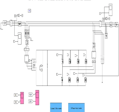
IV. SIMULATION MODEL
By using simulation models we can obtain the performance characteristics of the system very easily and quickly for analysis purpose. Here, we consider the performance analysis of IPFC based power quality conditioning device. In Fig.7. shows a simulink model of three phase four wire system to control in PID.
V.RESULTS AND DISCUSSION
System without IPFC
The output characteristics of the proposed system is shown in fig 8.From the figure it is seen that the output voltage got sagged and fluctuate during transmission at the time of 0.1sec.It is due to the non-linear load which is connected to the grid.
Figure 8. System without IPFC controller
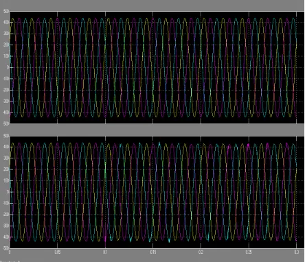
a) System with IPFC
From the figure 9. shown that the no sag in the load side voltage and amplitude remains same.Voltage sag is avoided by connecting IPFC controller in between the grid and the non-linear load
VI. CONCLUSION
In this paper presents the interline power flow controller (IPFC) is a Flexible AC transmission based device comprises voltage source converter for the series compensation in multiline transmission systems. The IPFC is capable to manage power between two or more interconnected lines. The voltage source converter injects reactive power which is used to flow the active power in the transmission lines. The series-parallel active filtering allowed balanced and sinusoidal input currents, as well as balanced, sinusoidal and regulated output voltages. By using dual control compensating strategy, the controlled voltage and current quantities are always sinusoidal. PID controllers can be used for better result and total harmonic distortion.
APPENDIX
Parameter Value
Three Phase voltage source
Amplitude:220 Vrms,Phase: 0 deg,Frequency: 50Hz
Three phase series RL branch
R: 1ohm,L: 0.2e-3H
Three phase Transformer
Rated power: 100 e3 VA,Frequency: 50Hz
Breaker Transient time: 0.1s,Breaker resistance: 0.01 ohm,Snubber resistance: 1e6
MOSFET FET Resistance: 0.1 ohm
Three phase Load Nominal voltage: 400 Vrms,Frequency: 50Hz,Active power: 10e3W
Universal bridge Snubber resistance: 1e5 ohm,Snubber capacitance: inf,RoN: 1e-3 ohm.
REFERENCES
1. G. Irusapparajan and S. Rama Reddy, Bharath University, Chennai, India, Jerusalem Engineering College, Chennai, India Experimental Results of Interline Power Flow Controller Systems, Research Journal of Applied Sciences, Engineering and Technology 3(7): 612-616, 2011, ISSN: 2040-7457 © Maxwell Scientific Organization, 2011
2. AnulekhaSaha, Priyanath Das and Ajoykumarchakraborty,”Performance Analysis and Comparison of Various FACTS Devices in Power System”, International Journal of Computer Applications, Volume 46-No.15, May2012.
3. D. Murali, Dr. M. Rajaram& N. Reka, “Comparison of FACTS Devices for Power System Stability Enhancement”, International Journal of Computer Applications, Volume8-No.4, October 2010.
4. J. Faiz, G. H. Shahgholian, and M. Torabian, “Design and simulation of UPFC for enhancement of power quality in transmission lines,” IEEE International Conference on Power System Technology, vol. 24, no. 4, 2010.
5. Z. H. Yuan, S. W. H de Haan, B. Frreira, and D. Cevoric, “A FACTS device: Distributed power flow controller (DPFC),” IEEE Transaction on Power Electronics, vol.25, no.10, October, 2010.
6. P. Salmeron, and S. P. Litran, “Improvement of the electric power quality using series active and shunt passive filters” IEEE Trans. Power Electron., vol. 25, no. 2, pp. 1058-1067, Ap. 2010.
7. P. Acuña, L. Moran, M. Rivera, J. Dixon, and J. Rodrigues “Improved Active Power Filter Performance for Renewable Power Generation Systems,” IEEE Trans. Power Electron., vol. 29, no. 2, pp. 687-694, Feb. 2014.
8. M. Ucar, S. Ozdemir, and E. Ozdemir, “A four-leg unified series–parallel active filter system for periodic and non-periodic disturbance compensation,” Electric Power Systems Research, vol. 81, pp. 1132-1143, 2011.
9. B. B. Ambati, and V. Khadkikar, “Optimal sizing of UPQC considering VA loading and maximum utilization of power-electronic converters,” IEEE Trans. Power Delivery, vol. 29, no. 3, pp. 1490-1498, Jun. 2014.