International Journal of Innovative Research in Science, Engineering and Technology
Volume 3, Special Issue 3, March 2014
2014 International Conference on Innovations in Engineering and Technology (ICIET’14)
On 21st & 22nd March Organized by
K.L.N. College of Engineering, Madurai, Tamil Nadu, India
Copyright to IJIRSET www.ijirset.com 475
M.R. Thansekhar and N. Balaji (Eds.): ICIET’14
Multi-Cell Modeling
M.S.Anish Fathima, Mrs.K.Latha, Dr.B.Umamaheshwari
Department of Control and Instrumentation Engineering, College of Engineering, Anna University,
Chennai, India.
Department of Power Electronics and Drives, College Of Engineering, Anna University, Chennai, India.
Department of Control and Instrumentation Engineering, College Of Engineering, Anna University,
Chennai, India
ABSTRACT--- Proton Exchange membrane fuel cells (PEMFC) have been received increasing attention from both the public and fuel cell community due to their great potential for transport applications. It has been widely considered as one of the most promising clean power sources because of its capability for zero-emission operation with high efficiency. In this paper, a compact model has been developed for Multi-cells in a Proton
Exchange Membrane fuel cell stack by using
MATLAB/SIMULINK. Activation, Ohmic and
Concentration losses are also considered to obtain better characteristics of fuel cell. This paper explicates how the fuel flow rate of a single fuel cell affects the stack voltage. Also this paper clearly shows that the membrane thickness of a cell affects the stack voltage in negative way. It has been shown through transient responses .This Multi-cell model will be useful for fault diagnosis methods.
KEYWORDS--- Proton Exchange Membrane Fuel cell, Membrane thickness, Multi-cells, PEMFC.
I. INTRODUCTION
Now a day the generation of power sources is an important one. All technologies are focused to generate the power. Fuel cells are considered to be the most efficient alternative energy conversion devices. Fuel cells generate electricity by an electrochemical reaction in which oxygen and a hydrogen-rich fuel combine to form water. Unlike internal combustion engines, the fuel is not combusted, the energy instead being released electro catalytically. This allows fuel cells to be highly energy efficient, especially if the heat produced by the reaction is also harnessed for space heating, hot water or to drive refrigeration cycles. Fuel cells are classified many types according to their operating temperature.
Among that Proton Exchange Membrane Fuel Cell (PEMFC) is considered as one of the most promising clean power sources because of its capability for
zero-emission operation with high efficiency. The proton
exchange membrane fuel cell (PEMFC) uses a water-based, acidic polymer membrane as its electrolyte, with platinum-based electrodes. PEMFC cells operate at relatively low temperatures (below 100 degrees Celsius) and can tailor electrical output to meet dynamic power requirements. Due to the relatively low temperatures and the use of precious metal-based electrodes, these cells must operate on pure hydrogen. PEMFC cells are currently the leading technology for light duty vehicles and materials handling vehicles, and to a lesser extent for stationary and other applications. The PEMFC fuel cell is also sometimes called a polymer electrolyte membrane fuel cell (also PEMFC).
At anode side the catalyst ionizes hydrogen as H+ ions and electrons [1],
2H 4H+ +4e-
The electrolyte pass only H+ ions to cathode side. The electrode only pass e-s through electric circuit to the cathode, this will produce the electric current.
At cathode side oxygen in the air reacts with H+ ions and electrons and will produce water,
Copyright to IJIRSET www.ijirset.com 476
M.R. Thansekhar and N. Balaji (Eds.): ICIET’14
Figure 1. Operation principle of Fuel CellThe V-I characteristics of PEMFC can be illustrated by polarization curve in Fig 2. This polarization curve can be divided into three regions ,
Activation overpotential, Ohmic overpotential,
Concentration overpotential [3]. In Activation
overpotential region, the dominant source of losses is due to the slowness of the chemical reactions. Ohmic loss occurs due to the internal resistance. Concentration loss
occurs due to mass transport limitations are
dominant.Concentration overpotential occurs when the chemical reaction is limited by the rate at which reactants can be supplied.
Current Density (mA/cm-2)
Fig 2. V-I Characteristics of PEMFC
It is the goal of the model developed here to enhance the performance of the fuel cell stack and one of the criteria for degradation of cell voltage has been found.
The voltage of a single fuel cell is quite small , about 0.7V [1] when drawing useful current, This means that to produce a useful voltage many cells have to be connected in series. Such a collection of fuel cells in series is known as a „Stack‟. The most obvious way to do this is by simply connecting the edge of each anode to the cathode of the next cell.
To improve the voltage cells are connected as a „Stack‟. If 10 cells are connected in serious it should produce nearly 7V , but practically it is not possible. The contribution of this paper is that what are all the reasons
behind that voltagedegradation . In this paper 10 cells, 5
cells are individually connected and the steady state and dynamic performance have been discussed. Many models are available for fuel cell but this model is quite simple and it will be very useful to detect the fault cell in a fuel cell stack.
This paper represents that the Steady state and Dynamic characteristics of Multiple cells in a Proton
Exchange Membrane fuel Cell stack. It shows how the stack performance varies with the variation of fuel flowrate of a single cell. Also how the change in membrane thickness of a single cell affects the stack voltage
Symbols Used
E0 -Cell EMF at standard pressure(V). Kr - Modelling constant
R -Universal gas constant. n - Number of cells
T -Stack temperature(K). Ko2 -Valve molar constant for Oxygen
F -Faradays constant(98485C). Ko2 ,Kh2,Kh2o -Valve molar constant for Oxygen
Hydrogen ,Water.
Po2,Ph2,Ph2o - The Partial Pressures of Oxygen,Hydrogen, Water (atm). Qo2 in ,Qh2 in ,Qh2o in
–The Inlet flowrate of Oxygen,Hydrogen, Water (Kmol/S).
Qo2out,Qh2out,Qh2oout –The Outlet flowrate of Oxygen, Hydrogen, Water (Kmol/S). Psat - Saturation Pressure (MPa).
II.DYNAMIC EQUATIONS FORMULATION
According to the conservation of energy and the ideal gas law, the partial pressure of each gas is proportional to the amount of gas in the stack, which depends on the gas inlet flow rate, gas consumption and gas outlet flow rate. Thus the state equations become,
=
(Q
inH2–Q
outH2
–Q
rctH2
) (1)
=
(Q
inO2–Q
outO2
–Q
rctO2
) (2)
=
(Q
inH2O–Q
outH2O
+Q
rctH2O
) (3)
At steady state condition the state equations becomes [2],
P
H2=
(
-2K
rI) (4)
P
O2=
(
-K
rI) (5)
P
H2O=
(2K
rI) (6)
The Dynamic Equations are,
Concentration over potential Region
0 0.2 0.4 0.6 0.8 1.0
1.2 Even the open circuit voltage is less than the
theoretcial no loss value
Ohmic over potential
Region
1000 200 400 600 800
0
Activation over potential Region ‘No loss’ voltage of 1.2 V
Copyright to IJIRSET www.ijirset.com 477
M.R. Thansekhar and N. Balaji (Eds.): ICIET’14
dP
H2=
(
-2K
rI-P
H2) (7)
dP
O2=
(
-K
rI-P
O2) (8)
dP
H2O =(Q
inH2O
+2K
rI- P
H2O) (9)
Where,
=
=
=
Due to the irreversibilities the fuel cell voltage becomes [1],
Vcell
=E
0+
-V
act-V
ohmic-- V
con---- (10)
Where,
E
0=
open circuit voltage(V)=0.87V
V
act= Bln(CI) (11)
V
ohmic=IR
ohm(12)
=
(13)
=
membrane thickness( m)
V
conc=I(c
2(I/imax))
c1
(14)
C
1=2;
C2=(8.66*T-0.068)*( + )+(-1.6e-T+0.25);
III. RESULTS AND DISCUSSION
A. Causes of Water Flooding
Water flooding play an important role in the performance of Proton Exchange membrane Fuel cell. Some main reasons for this water flooding are, Due to the “Back-Diffusion” some water molecules are diffused from cathode to anode [8]. The another reason, water will be dragged from anode to cathode by protons moving through the electrolyte.,the another reason ,Due to the Humidification of Fuel and Oxygen. Accumulation of excess water limits the fuel flow rate therefore the performance decreases. During this flooding event
Membrane water content increases thus membrane thickness increases.
B. Causes of change in Membrane Thickness
One of the main reason for change in membrane thickness is water flooding, due to this water flooding the water content in membrane will increase. The membrane thickness has negative effect on the performance of the cell because as the thickness increases, the moving time of proton from anode to cathode increases [9], hence it delays the reaction on the cathode side which results in a stack voltage.
C. Steady state Responses
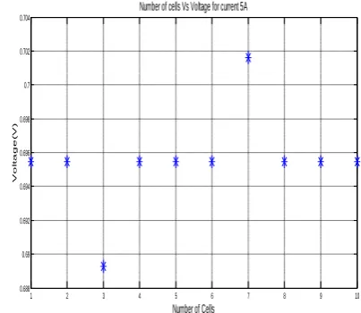
The Fig 3. Shows that the effect of membrane thickness on cell voltage. For a particular current performance of individual cells is plotted. 10 cells are connected individually and the membrane thickness of two cells are varied with other cells for a current 18 A.
1 2 3 4 5 6 7 8 9 10
0.688 0.69 0.692 0.694 0.696 0.698 0.7 0.702 0.704
Number of Cells
V
o
lt
a
g
e
(
V
)
Number of cells Vs Voltage for current 5A
Fig 3. Steady state response of Effect of Membrane thickness on cell voltage.
D. Transient Responses
Copyright to IJIRSET www.ijirset.com 478
M.R. Thansekhar and N. Balaji (Eds.): ICIET’14
Fig 4. Transient response of Effect of fuel flow rate On cell voltage.
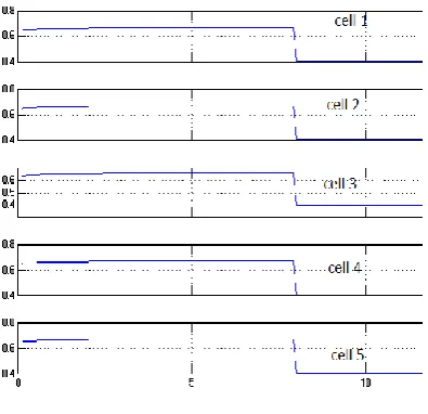
In Fig 5. the performance variation of 5 cells due to the change of membrane thickness has been plotted.
Fig 5. Transient response of Effect Membrane thickness on cell voltage.
As the thickness of the membrane is increased, the cell voltage is found to be decreasing 4% to 8% .Also as the thickness of the membrane is decreased, the cell voltage is found to be increasing 4% to 9%. Cell 1, Cell 3 and Cell 5 have the same membrane thickness (50µm) Cell 2 has (70µm) and Cell 4 has (30µm).Thus the stack voltage reduced.
TABLE 1. shows that the performance variation due to the change of membrane thickness. The membrane thickness affects the cell voltage in a negative way because it reduces the reaction time on the cathode side by delaying the proton time to reach the cathode side. As the thickness increases, the proton travelling time increases and therefore the cell voltage decreases.
TABLE 1. PERFORMANCE VARIATION DUE TO CHANGE IN MEMBRANE THICKNESS
IV. CONCLUSION
In this paper Dynamic model has been developed for Muliple cells of Proton Exchange Membrane Fuel cell stack by using MATLAB/SIMULINK Software .The steady state performance of multiple cells also discussed. This paper shows that how the membrane thickness of a single cell affects the stack voltage . The reasons behind that change of membrane thickness are also discussed. The further progress is going on CFCT. In Future ,this model will be useful for fault detection techniques.
ACKNOWLEDGMENT
The authors would like to express sincere thanks to Dr.N.RAJALAKSHMI, Senior Scientist, Centre for Fuel Cell Technology, Chennai, for her support to do this work.
REFERENCES
[1] Larminie J, Dicks .A, “Fuel cell systems explained”, 2nd Edition
UK: Wiley;2003
[2] Pukrushpan J.T, Stefanopoulou A.G, and Peng H, “Control of fuel cell power systems; principles ,Modeling ,Analysis and Feedback design”,1st ed. London, UK, Springer- Verlag,2004.
[3] U.S.Department of Energy, Fuel cell Handbook(Sixth Edition). DOE/NETL-2002/1179.
[4] Pucheng pei , Minnggao Ouyang “Hydrogen pressure drop characterized in a fuel cell Stack” published in International Journal of Hydrogen Energy 3(2006),pp 371-377.
[5]Hong Liu, Peiwen Li, “Maintainig equal operating conditions for all cells in a fuel cell stack using an external flow distributor”.Hydrogen Energy Publicaitons pulished by Elsevier Ltd,2013,pp 3757-3766. [6] Friede Wolfgang, Rael Stephane, Davat Bernard. Mathematical model and characterization of the transient behavior of a PEM fuel cell. IEEE Transactionson Power Electronics 2004.
[7] Yibo Zhou, Kui Jiao,Qing Du, “Gas Diffusion layer deformation and its effect on the ransport characterisitics and performance of proton exchange membrane fuel cell” published in International Journal of Hydrogen Energy 38(2013), 12891-12903.
[8] Thomas J.Mason,Jason Millichamp, “A study of the effect of water management and electrode flooding on the dimentional change of polymer electrolyte fuel cells” published in Journal of Power Sources
242( 2013) 70-77.
[9] Elsinawi, T.A.H.Ratlamwala, “Performance Analysis of a Newly Designed PEM Fuel cell”, IEEEInternational Energy Conference 2010.
Cell 1 50µm
Cell 2 70µm
Cell 3 50µm
Cell 4 30µm
Cell 5 50µm
Current I (A)
Cell Voltages (V)
8 0.64 0.60 0.64 0.68 0.64
16 0.35 0.27 0.35 0.43 0.35
6 0.68 0.65 0.68 0.70 0.68
10 0.58 0.53 0.58 0.63 0.58
V
o
ltag
e(
V
)
Time(S)
Time(S)
V
o
ltag
e(
V