http://www.scirp.org/journal/wjet ISSN Online: 2331-4249 ISSN Print: 2331-4222
DOI: 10.4236/wjet.2017.54B007 Oct. 12, 2017 62 World Journal of Engineering and Technology
Permittivity Measurement of Low-Loss
Substrates Based on Split Ring Resonators
Jianyi Li
92493 Troops, Huludao, China
Abstract
In this paper, we present the complex permittivity measurement of low-loss substrates based on a microstrip-line-excited split-ring resonator (SRR). Per-mittivity of an unknown substrate is calculated based on the change in oscilla-tion frequency of SRR caused by the material-under-test (MUT) above the SRR. Theoretical analysis and results of the simulations and experiments demon-strate the microstrip-line-excited SRR can be used to effectively improve mea-surement sensitivity. Simple equations for meamea-surement of low-loss substrates using SRR are proposed and experimentally verified.
Keywords
Split-Ring Resonators (SRR), Permittivity, Non-Contact Measurement
1. Introduction
Complex permittivity of the material is an important parameter to reflect the in-teractions of matter and magnetic fields and accurate measurement of complex permittivity is widely applied in fabrication process, quality control and biosens-ing.
Many methods have been proposed to measure the complex permittivity such as free-space methods, transmission-line methods and resonance methods. Free-space methods are based on the measurement of the free-space reflection and trans-mission coefficients of the sample placed between the antennas. This method is nondestructive and contactless; however it is more suitable for frequency higher than 30 G and the diffraction effects around the sample edges are difficult to elim-inate [1] [2] [3]. Compared to the free-space methods, transmission-line methods are much cheaper and more suitable for wideband measurements. The most com-mon structures of transmission-line methods are rectangular waveguide and coaxial
How to cite this paper: Li, J.Y. (2017) Permittivity Measurement of Low-Loss Sub-strates Based on Split Ring Resonators. World Journal of Engineering and Technology, 5, 62-68.
https://doi.org/10.4236/wjet.2017.54B007
DOI: 10.4236/wjet.2017.54B007 63 World Journal of Engineering and Technology line [4] [5] [6]. The resonance methods are the most accurate methods to meas-ure the complex permittivity by measuring the shift in the resonance frequency and the change in the quality factor. The resonance method offer high accuracy but have a limited bandwidth [7] [8].
In this paper, we present a non-invasive permittivity measurement of low-loss substrates based on a microstrip-line-excited split-ring resonator (SRR). Permit-tivity of an unknown substrate is calculated based on the change in oscillation frequency of SRR caused by the material-under-test (MUT) above the SRR. The microstrip-line-excited SRR has small size and low require of the sample’s shape. Theoretical analysis and results of the simulations and experiments demonstrate the new sensor can be used to effectively improve the measurement sensitivity.
2. Theory
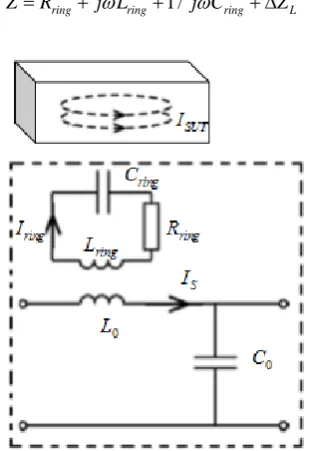
The corresponding equivalent circuit is shown in Figure 1 [9]. Based on circuit theory, the input impedance for the SRR without the SUT is
0 ring 0 ring 1 0 ring
Z =R + j
ω
L + jω
C (1)The relationship between the impedance perturbation and the SUT’s permit-tivity has been well investigated in many papers [10]. Assume the SRR carries a current with a magnitude I, the impedance perturbation caused by the SUT is
( )
2( )
(
)
( )
1
inc r tot
L V
Z j
ω
I E r ε
E r dV∆ = ⋅
∫∫∫
⋅ − ⋅ (2)where Einc and Etot are the electric fields with the SUT and without the SUT. inc
E denotes the electric field induced by the resonance current I in the load
coil, and Etot denotes the total field. Thus the input impedance for the SRR with
the SUT is
1 /
ring ring ring L
[image:2.595.296.457.467.693.2]Z=R + j L
ω
+ j Cω
+ ∆Z (3)DOI: 10.4236/wjet.2017.54B007 64 World Journal of Engineering and Technology Equation (2) is exact for the change in impedance due to SUT perturbations, but is not in a very usable form since we generally do not know Etot. So the
re-lationship between ∆ZL and εr is not intuitive, however we can make some
approximation in some restrictions. 1) Contact methods
In this section, we provide a simple setup for the contact measurement with high sensitivity, as in Figure 2. If the permittivity of the SUTs is small ( 10
r ε ≤ ),
then we can approximate the Etot by the original fields Einc. Equation (2) can be simplified to
(
r 1)
L
Z jα ε
∆ ≈ ⋅ − (4)
Substituting (4) into (3), we can get
1 /
(
1)
ring ring ring r
Z
=
R
+
j L
ω
+
j C
ω
+
j
α ε
−
(5)For a given configuration, α is a pure real constant. When the SRR resonates, imaginary part of the impedance is zero. The SUTs we measured are low-loss substrates, so we can approximate the complex permittivity
r
ε
by εr (the realpart of
r
ε
). According such conditions, we can achieve1 / ( 1) 0
sLring sCring r
ω
−ω
+α ε
− = (6)0Lring 1 / 0Cring 0
ω
−ω
= (7)where
s
ω is the resonant frequency of the SRR with SUT and ω0 is the
reso-nant frequency without SUT. Substituting (7) into (6), we can obtain
(
)
2
1 / f εr 1
∆ ≈ Α − (8)
2) Non-contact methods
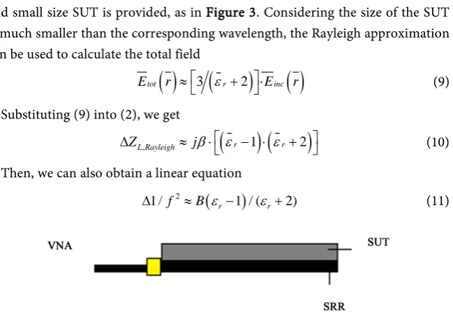
In theory, for all the setup configuration the impedance perturbation is ob-tained by (2). In order to simplify (2), a contactless measurement for low-loss and small size SUT is provided, as in Figure 3. Considering the size of the SUT is much smaller than the corresponding wavelength, the Rayleigh approximation can be used to calculate the total field
( )
3(
2)
( )
tot r inc
E r ≈
ε
+ ⋅E r (9)Substituting (9) into (2), we get
(
)
(
)
, r 1 r 2
L Rayleigh
Z j
β
ε
ε
∆ ≈ ⋅ − ⋅ + (10)
Then, we can also obtain a linear equation
(
)
2
1 / f B εr 1 / (εr 2)
[image:3.595.216.541.480.706.2]∆ ≈ − + (11)
DOI: 10.4236/wjet.2017.54B007 65 World Journal of Engineering and Technology
3. Experiment
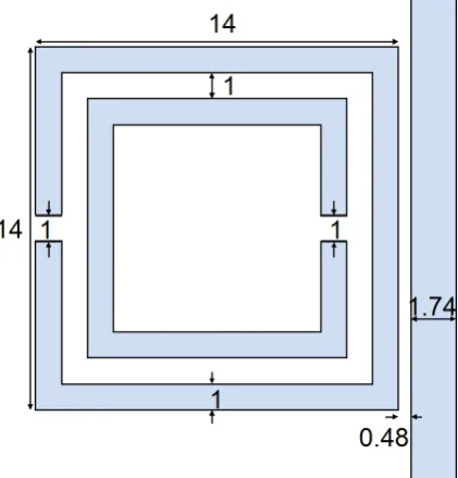
In this section, we use two setups to measure the permittivity of the SUTs, one is the contact measurement for high sensitivity, the other is the contactless one. The microstrip-line-excited SRR is fabricated using printed circuit board tech-nology. The implementation of the sensor is shown in Figure 4. CST microwave studio is used to simulate the mode and a VNA (AnritsuS331E) is used to ure the resonate frequency. Figure 5 shows the simulation results and the meas-ured reflection coefficients of the SRR without SUTs. The divergence between the simulation and measurement is mainly due to errors in the fabrication process. Four substrates with the same size were prepared for the permittivity measurements.
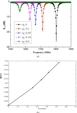
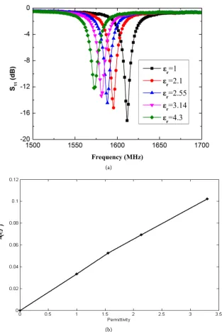
[image:4.595.288.461.313.446.2]Figure 6 shows the contact measurement result when the SUT changes and Figure 7 shows the contactless measurement results. The resonant frequency reduces as the sample permittivity increases in agreement with the theoretical analysis and simulation results.
Figure 3. A typical setup of non-contact measurement.
[image:4.595.269.480.482.702.2]DOI: 10.4236/wjet.2017.54B007 66 World Journal of Engineering and Technology
Figure 5. S-parameters of the microstrip-line-excited split-ring resonator without SUTs.
(a)
(b)
Figure 6. (a) Contact measured S11 for different SUTs; and (b) The measured frequency
[image:5.595.240.509.291.683.2]DOI: 10.4236/wjet.2017.54B007 67 World Journal of Engineering and Technology
(a)
(b)
Figure 7. (a) Contactless measured S11 for different SUTs; and (b) The measured
fre-quency with respect to permittivity.
4. Conclusion
In conclusion, the theoretical analysis and results of the simulations and experi-ments demonstrate the microstrip-line-excited SRR can be used to effectively im-prove the measurement sensitivity. Simple equations for measurement of low-loss substrates using SRR are proposed and experimentally verified.
References
[image:6.595.219.533.67.535.2]DOI: 10.4236/wjet.2017.54B007 68 World Journal of Engineering and Technology
[2] Kadaba, P.K. (1984) Simultaneous Measurement of Complex Permittivity and Per-meability in the Millimeter Region by a Frequency-Domain Technique. IEEE Trans. Instrum. Meas., IM-33, 336-340. https://doi.org/10.1109/TIM.1984.4315236
[3] Nitsche, R.G. and Biebl, E.M. (1994) A Free-Space Techniqque for Measuring the Complex Permittivity and Permeability in the Millimeter Wave Range. 1994 IEEE MTT-S. Microwave Symp. Dig., 1465-1468.
[4] Chin, T.C. (2005) Permittivity Measurement Technique for a Dielectric Strip Using a Rectangular Waveguide. Proc. IEEE Int. Symp. Antennas Propagat. Soc., 3, 314-317. [5] Blackham, D.V. and Pollard, R.D. (1997) An Improved Technique for Permittivity
Measurements Using a Coaxial Probe. IEEE Trans. Instrum. Meas., 46.
https://doi.org/10.1109/19.676718
[6] Kehn, M.N.M., Shafai, L., Safari, F. and Noghanian, S. (2009) Permittivity Measure-ment of Disk and Annular Dielectric Samples Using Coaxial Transmission Line Fix-tures. Part ІІ: Experimentation and Accuracy Analyses. Can. J. Elect. Comput. Eng., 34. [7] Meng, B., Booske, J. and Cooper, R. (1995) Extended Cavity Perturbation
Tech-nique to Determine the Complex Permittivity of Dielectric Materials. IEEE Trans. Microw. Theory Tech., 43, 2633-2636. https://doi.org/10.1109/22.473190
[8] Li, S., Akyel, C. and Bosisio, R.G. (1981) Precise Calculation and Measurements on the Complex Dielectric Constant of Lossy Material Using Cavity Perturbation Tech-niques. IEEE Trans. Microw. Theory Tech., MTT-29, 1041-1048.
[9] Baena, J., Bonache, J., Martin, F., Sillero, R., Falcone, F., Lopetegi, T., Laso, M., Gar-cia-Garcia, J., Gil, I., Portillo, M. and Sorolla, M. (2005) Equivalent Circuit Models for Split-Ring Resonators and Complementary Split-Ring Resonators Coupled to Planar Transmission Lines. IEEE Trans. Microw. Theory Tech., 53, 1451-1461.
https://doi.org/10.1109/TMTT.2005.845211
[10] Auld, B.A. and Moulder, J.C. (1999) Review of Advances in Quantitative Eddy Cur-rent Nondestructive Evaluation. J. Nondestruct. Eval., 18, 3-36.