University of Twente
EEMCS / Electrical Engineering
Control Engineering
Design of a hard real-time, multi-threaded
and CSP-capable execution framework
Robert Wilterdink
MSc report
Supervisors:
Summary
Nowadays, embedded systems are designed for multiple and more demanding tasks, whereas previously they had a single use case and were less demanding. One can think of automated robot vacuum cleaners in the past versus complete household robots presently. This progress is possible due to improved hardware architectures, with multiple parallel cores/processors, and increased resources for embedded systems. The formal language Communicating Sequential Processes (CSP) is designed to aid development of such parallel computing software.
In the past, the CTC++ framework was developed to implement CSP models on embedded sys-tems. This framework was designed for single core/processor architectures and its design now is outdated.
To design a new framework, which can also fully utilize future embedded architectures, state of the art frameworks and libraries were investigated. They are analyzed on their software archi-tecture, platform independence, timing and real-time capabilities, and scalability and extensi-bility. A comparison on these subjects is included as well.
The LUNA framework described in this report is a hard real-time, threaded, multi-platform, CSP capable and a component based framework. Many of its components can be enabled/disabled separately to achieve high scalability.
For the first framework implementation the hard real-time QNX operating system (OS) is cho-sen, since it includes CSP similar rendezvous channels. But, as it turned out, QNX’ rendezvous channels are not usable for some of the rather advanced CSP rendezvous communication op-erations.
Additionally, a distinctive implemented feature is the real-time logger. It can be used to transfer log messages, (a)periodic (control) signals and CSP execution traces to a development PC for further processing, without destroying the real-time constraints.
To analyze LUNA’s performance a simple robotic setup is implemented. The results show that the new CSP design is more efficient and faster than the CT library.
Samenvatting
Tegenwoordig worden embedded systemen ontworpen voor zowel meerdere als veeleisendere taken. Vroeger hadden deze echter een enkele toepassing en waren ze minder veeleisend. Men kan denken aan geautomatiseerde robotstofzuigers in het verleden versus volledig geautoma-tiseerde huishoudrobots op dit moment. Deze vooruitgang is mogelijk gemaakt door verbe-terde hardware-architecturen met meerdere parallele cores/processors en meer rekencapaci-teit voor embedded systemen. De formele taal Communicating Sequential Processes (CSP) is ontworpen met als doel het vereenvoudigen van het ontwikkelen van dergelijke paralelle soft-ware structuren.
In het verleden is het CTC++ framework ontwikkeld om CSP modellen te implementeren op embedded systemen. Dit framework is echter ontworpen voor enkelvoudige core/processor architecturen. Het ontwerp is nu achterhaald.
Om tot een nieuw framework te komen, dat ook volledig benut kan worden op toekomstige embedded architecturen, zijn moderne frameworks en bibliotheken onderzocht. Ze zijn gea-nalyseerd op hun software architecture, platform onafhankelijkheid, timing en real-time eigen-schappen en tot slot schaalbaarheid en mogelijkheid tot uitbreiding. Het verslag bevat tevens een uitgebreide vergelijking van deze onderwerpen.
Het LUNA framework zoals beschreven in dit rapport is een hard real-time, multi-threaded, multi-platform, CSP-capabel en component-gebaseerd framework. Een groot deel van de com-ponenten kan apart in- en uitgeschakeld worden waarmee een hoge schaalbaarheid wordt be-reikt.
Voor een eerste framework implementatie is het hard real-time QNX besturingssyteem geko-zen, omdat deze CSP-vergelijkbare rendezvous communicatie kanalen biedt. Uiteindelijk ble-ken deze QNX rendezvous kanalen alsnog niet geschikt voor de redelijk geavanceerde CSP ren-dezvous communicatie.
Een interessante extra feature is de real-time logger. Deze kan log berichten, (a)periodieke (regelaar) signalen en de CSP executie volgorde doorsturen naar een ontwikkel PC voor verdere analyse zonder dat het real-time gedrag wordt beïnvloed.
Om de LUNA prestaties te kunnen analyseren is een eenvoudige robot setup geïmplementeerd. De verkregen resultaten tonen aan dat het nieuwe CSP ontwerp efficiënter en sneller is dan de CT-bibliotheek.
Preface
This thesis marks the end of my Computer Science and Electrical Engineering studies at the University of Twente. The choice for the additional Electrical Engineering master originates from my interest in mechatronics and robotics. The combination of both hopefully gives me an extra challenge.
Looking back, the experiences gained during both studies, among others my internship in Eng-land, and extracurricular activities made me the person who I am today. The extracurricular activity I have perceived as most educational and enjoyable, was being part of the Arashi board 2007-2008 (sports association). Over all, it was a pleasant period of my life in which a lot of good memories were made.
I would like to thank my graduation committee dr.ir. Jan Broenink, ir. Bert Molenkamp, ir. Marcel Groothuis and ir. Maarten Bezemer for their support on this assignment. Special thanks go out to my daily supervisor, Maarten Bezemer, for the many interesting discussions we had on the development of the software framework and my thesis. Writing a paper together and presenting the framework on the CPA 2011 conference was a nice bonus for me.
Thanks also go to Raymond, Youri and the other students for their tips, discussions and the good times during this project. I have enjoyed this very much and it has helped me to accom-plish this thesis.
Most of all, I want to thank my parents and my girlfriend, Alette Beusink, for giving me the opportunity to do two studies and providing me with the their support and (extreme) patience during my study.
Robert Wilterdink
Contents
1 Introduction 1
1.1 Context . . . 1
1.2 Goals and approach of the project . . . 2
1.3 Evaluation objectives . . . 3
1.4 Thesis outline . . . 3
2 Background 5 2.1 Frameworks versus libraries . . . 5
2.2 Hardware . . . 5
2.3 Operating Systems . . . 6
2.4 Real-time . . . 9
2.5 QNX . . . 9
2.6 Software testing . . . 10
2.7 Design methodology . . . 10
3 Analysis 15 3.1 Domain analysis . . . 15
3.2 Requirements . . . 15
3.3 Conclusions . . . 18
4 Framework and library research 19 4.1 Introduction . . . 19
4.2 Approach . . . 21
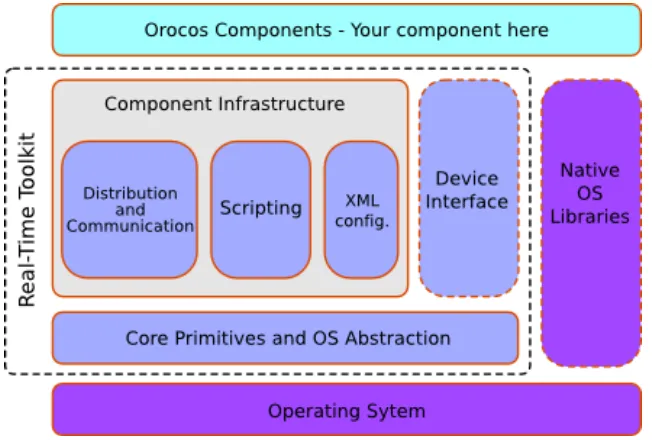
4.3 Orocos . . . 21
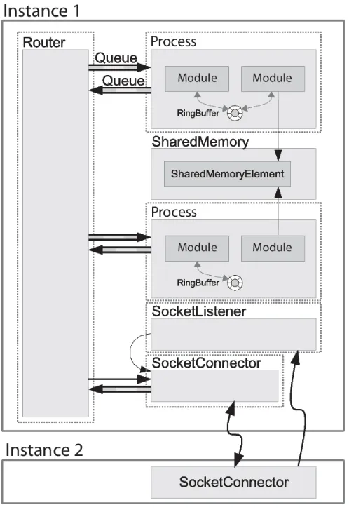
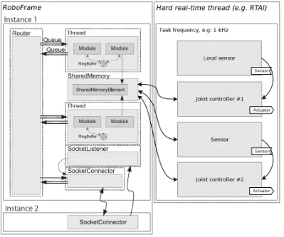
4.4 RoboFrame . . . 27
4.5 CT library . . . 30
4.6 Boost . . . 33
4.7 POCO . . . 35
4.8 Conclusions . . . 37
5 Design & implementation 41 5.1 Architecture and approach . . . 41
5.2 Detailed designs of components . . . 47
5.3 Other components . . . 74
5.4 CSP component . . . 77
5.5 Conclusions . . . 79
6.1 Qualitative evaluation . . . 81
6.2 Quantitative evaluation . . . 86
7 Conclusions & recommendations 87 7.1 Conclusions . . . 87
7.2 Recommendations . . . 88
A Appendix - Domain analysis 91 A.1 Jiwy . . . 91
A.2 Production Cell . . . 92
A.3 Humanoid Head . . . 94
A.4 TUlip . . . 95
B Appendix - C++ language exceptions 97 C Appendix - Atomic component 99 D Appendix - Timers and counters 100 D.1 Time Stamp Counter . . . 100
E Appendix - Threading use cases 102 F Appendix - CSP Threading use case 104 G Appendix - QNX AnyIO driver 106 H Appendix - RTLogger examples 107 H.1 Recording RTLogger information . . . 107
H.2 Visualizing CSP traces . . . 108
H.3 Visualizing (control) signals with 20-sim . . . 112
I Appendix - LUNA CPA 2011 conference paper 115
1 Introduction
1.1 Context
Nowadays embedded systems are designed for multiple and more demanding tasks, whereas previously they usually had a single use case and were less demanding. One can think of au-tomated robot vacuum cleaners in the past versus complete household robots presently. So, an embedded system is a complete device which not only contains electronics and mechani-cal parts, but also a (special-purpose) computer, which organizes the various tasks and execute their functions to control the hardware in a safe and efficient manner. These increased require-ments obviously result in more complex control software, as the software is responsible for the ‘smart’ behavior of the device.
The Control Engineering (CE) group at the University of Twente deals with the realisation of complex (embedded) control structures for mechatronic setups. These mechatronic setups currently range from humanoid robots to miniature production plants to autonomous pipe inspection robots. On a software level these setups require, amongst others, hard real-time computing constraints, multiple parallel processes and sophisticated design patterns which facilitate safe and easy software development.
A proven approach, to coordinate several computational entities running at the same time (i.e. a concurrent system), is the process algebra Communicating Sequential Processes (CSP) devel-oped by Hoare (1985) and Roscoe et al. (1997). CSP theory can also be used to prove correctness, deadlock freeness and lifelock freeness of a model.
In the past a graphical modelling tool, called gCSP (Jovanovic et al., 2004), has been developed at the CE group to aid modelling of concurrent systems with CSP. This tool is able to generate code from a model which can be executed on a PC or on a (real-time) hardware target. The gen-erated code makes use of the Communicating Threads (CTC++) library (Hilderink et al., 1997; Orlic and Broenink, 2004), which provides a framework for the CSP language. During develop-ment one can also monitor the application in gCSP through an animation facility (Steen, van der et al., 2008). The complete overview is shown in Figure 1.1.
gCSP model
Code generation
CT library
Executable +
Animation gCSP Tool
Figure 1.1:Overview of the gCSP and CT framework
The current CT library is a product of many years of research and development, but unfortu-nately the library has become outdated:
• The scheduler and all processes run in the same software thread. The Operating System (OS) does not cooperate with these internal processes. The CT library therefore intends to deliver any external events like timer interrupts to the appropriate process. The cur-rent scheduler cannot guarantee when this event is handled. This sometimes results in inconsistent and inadequate timing behavior.
• The years of ongoing development did not benefit the software quality and obfuscated the original design.
For modern frameworks it is advantageous to employ an OS, because common functionality, such as parallel processing and network facilities, is already available and therefore will con-siderably shorten development time. The use of an OS has become a viable choice, because computing resources have increased a lot since the development of the CT library. Unfortu-nately, not all OS’ are hard real-time capable, but for example QNX (QNX Software Systems, 2011) is. In addition QNX offers rendezvous communication channels which are similar to CSP rendezvous channels.
1.2 Goals and approach of the project
The goal of this project is to design a new hard real-time, multi-threaded and CSP-capable execution framework. Furthermore, the framework should be platform independent.
The QNX operating system offers rendezvous communication channels by default and, there-fore, seems to offer a good base for CSP implementations, which will hopefully lighten the task at hand. As a result, the main research question to be answered in this thesis: Is QNX a valid choice to implement CSP based communicating threads? The idea to use QNX is not new (Veld-huijzen, 2009). The difference is that a complete resigned is considered and not only a reimple-mentation, which limited the design choices considerably. Furthermore, a non real-time CSP framework (C++CSP2, 2009) is also investigated.
In the future the framework should be usable on different platforms to make it wider appli-cable. Multiple framework projects have solved this problem in different manners, without a clear solution yet. Therefore a subgoal of this thesis is to determine how a platform indepen-dent framework should be designed. This will be accomplished by analyzing state of the art frameworks on their software architecture, platform independence, timing and real-time ca-pabilities, and scalability and extensibility. The gained knowledge is then applied for the new framework design.
The current implementation of the CT library has a tight integration with the CSP execution engine, so it is not possible to use the library without being forced to use CSP as well. This is an obstacle to use the library from a generic robotics point of view and might result in ignoring the CT library altogether. Furthermore, a loose coupling between CSP processes and the rest of the framework will probably enable more research opportunities. Thus, the second subgoal of this thesis is to investigate whether the CSP language implementation and framework can be loosely coupled. The results from investigating the CT library and the non real-time C++CSP2 framework are used for this part of the design as well.
The main question to be answered in this thesis:
Is QNX a valid choice to implement CSP based communicating threads?
Minor questions:
a How should a platform independent framework be designed?
b How can the CSP execution engine be designed, such that the CSP implementation is loosely coupled to the rest of the framework?
1.3 Evaluation objectives
The project can be qualitatively evaluated with the research questions posed in the previous section.
The quantitative evaluation will be performed with a real robotic setup with two degrees of freedom. Using this setup hard real-time properties can be empirically proven and the new framework can be compared with the CT library, which also has been used with this setup in the past. The CSP community’s (standard) Commstime test is used to compare the performance also with a non real-time CSP library.
1.4 Thesis outline
2 Background
This chapter provides background information. Section 2.1 explains the difference between frameworks and libraries. Next, the considered hardware architectures in this thesis are dis-cussed. Section 2.3 explains general Operating System (OS) concepts. Then hard, soft and non real-time are explained in Section 2.4. Following, the hard real-time QNX OS will be shortly introduced. Section 2.6 presents common testing methods and levels in software engineering. Last, Section 2.7 discusses the design methodology used in the CE group.
2.1 Frameworks versus libraries
A library is essentially a set of reusable functions, usually organized in classes. Each function invocation performs some work and then returns control to the client. A library, therefore, is a set of components to develop an application with.
A framework embodies a reusable abstract design, which should be extended on specific points. The framework’s code then calls this code at these points, to achieve the intended framework behavior. A framework therefore is a set of components and design patterns, which specify the behavior of an application.
2.2 Hardware
The CE group currently has multiple custom setups and demonstrators, which are controlled by a few different standard hardware architectures. For this thesis, these hardware architectures can be divided in two groups:
1. x86/PowerPC/ARM architectures, with enough resources to run a real-time OS
These architectures in combination with enough resources (such as memory) are able to run general purpose OSs as well as real-time OSs. The x86 and PowerPC architectures are also employed in consumer computers. The ARM architecture is mostly used in embed-ded setups or handhelds.
The OS capable hardware requirement facilitates framework design, since a lot of required functionality is already being taken care of by the OS. For example multi-threading and common user input/output facilities. Furthermore, functionality non-essential to most applications, such as debugging support, will also be present. Both will shorten develop-ment time considerably.
2. Other architectures, such as FPGAs
This category comprises of all hardware architectures not capable of running a general purpose OS nor real-time OS, such as FPGAs and AVR micro controllers. These are mostly used for small setups or for dedicated functions of a setup, like PWM signal generation.
The PC/104-stack mentioned in Chapter 6 is an example of a small x86 form-factor embedded computer with additionally various I/O boards. One of the I/O boards comprises a FPGA to implement multiple encoder counters and PWM signal generators.
2.3 Operating Systems
An Operating System (OS) is a collection of software, consisting of programs and data, that runs on computers, manages computer hardware resources, and provides common services for ex-ecution of various application software. The OS acts as an intermediate between application programs and the computer hardware, although the application code is usually executed di-rectly by the hardware and will frequently call the OS for support or be interrupted by it. The latter, for instance, can be the case when multiple programs time-share a CPU.
2.3.1 Organization
Modern OSs use a kernel-based architecture. A kernel has facilities to receive resource requests and grant access to resources such as allocating space for a new file or creating a new process. So, the kernel is the gate-keeper to the computer’s resources. Applications use system calls to interface with a kernel.
Except for single purpose OSs, all modern OSs are both multitasking and multi-user. Since computers are limited by the number of cores/CPUs available, the OS must perform a trick to actually perform more than one (or a few) tasks at a time. The kernel uses time sharing for each available core/CPU at a high speed, such that it appears that the computer is multitasking for multiple users. Because the system is sharing resources a gate-keeper is needed for two primary reasons; Facilitating time sharing and to make sure users do not violate other users’ resources.
Time sharing is accomplished by context switching, which consists of the following steps: 1. Save the current processes context: registers and program execution (counter).
2. Load another process’ context and perform its operations from the point it was inter-rupted.
3. After the allotted time is over1, repeat from beginning.
The kernel also has three other resource management tasks, besides time sharing a core/CPU:
• Servicing requests from applications
When any application requires resources, it must access the resource via the kernel indi-rectly. The kernel processes the request and returns the result. For example, on a memory allocation request the kernel allocates the memory to the process and makes sure that the allocated memory is not in use.
• Servicing system interrupts
Computer systems have a set of hardware and software interrupts. An interrupt interrupts the current process because of a condition. An interrupt can be for instance a timer event, i.e. after a pre-specified time has elapsed, the OS is notified of this.
• Managing system resources
Kernels also performs internal management, that is not directly related to services. The kernel has to keep track of what resources it has provided to applications and may collect information about other aspects of the system as well.
The OS has a variety of protection methods to prevent unauthorized access to system resources. The strongest protection is achieved in corporation with a CPU that has different privilege lev-els. Modern CPUs have at least two privilege levels: kernel level and user level.
If properly designed, only the OS kernel code is allowed to execute in an unrestricted mode (kernel level) on the processor. Everything else runs in a restricted mode (user level) and must use a system call to have the kernel perform any operation that could potentially damage or compromise the system on its behalf. This makes it impossible for untrusted programs to alter
or damage the system. Mode protection may extend to resources beyond the CPU hardware itself, for example protecting process memory boundaries.
So, a system call changes the execution mode from user level to kernel level and back when done. As a side effect other operations might also take place, such as memory swapping. Thus, the disadvantage of multiple privilege levels is a (slight) performance drop.
Multiple types of kernels exist: nano-, micro- and monolithic kernels. The exact type of kernel does not matter for this thesis, since the OS Application Programmers Interface (API) hides this anyway.
2.3.2 Processes and threads
An application, in general, is instantiated by the OS as a process. Processes have their own memory space, which boundaries are guarded by the CPU. Furthermore, OS resources are often assigned to the whole process.
In OS terms, the process is a thread container. A thread is an execution entity, which is sched-uled by a scheduling algorithm onto the CPU. Threads share, with other threads belonging to the same process, their application code, data and other OSs resources, such as open files and signals. Support for threads may be provided at either the user level (user threads) or by the kernel (OS threads).
OS threads, also called kernel threads, are supported directly by the OS. The kernel provides support for the OS to create, schedule and manage threads in kernel space.
User threads are supported above the kernel level and are implemented by a thread library at the user level. The library is responsible for creating, scheduling and management of the threads, without support from the kernel. A user thread is executed by an OS thread and at most one user thread can run simultaneously in one OS thread. Most likely, the OS is unaware of the presence of user threads and as a consequence does not support user thread preemption.
User threads are generally faster to create and manage than kernel threads, since no system calls are necessary. However, preemption (rescheduling) of user threads is only possible on explicit request. So, if a blocking system call is performed on a user thread, the system call stalls the underlying OS thread and thereby all user threads in the container. When a blocking system call is performed on an OS thread, the kernel is able to preempt the thread and schedule another thread for execution.
2.3.3 Multi-threading models
The different multi-threading models, that are possible for a combination of OS and user threads, are depicted in Figure 2.1. The one-to-one threading model discards the user thread-ing advantages, since for every user thread a ‘heavy weight’ OS thread is needed.
OS
user level kernel level
one-to-one many-to-one
many-to-many
user thread
OS thread
OS OS OS OS OS OS
The many-to-many model can be used to prevent the ‘one system call can block all’ problem, but there are three potential problems:
• If more OS threads are used than cores/CPUs are available, expensive OS thread context switches are needed to run all user threads.
• Since the OS thread priorities take precedence over user thread priorities for scheduling (as will be explained later), a priority inversion problem might be created in the previ-ous case as well. Because, a high priority’s user thread running time is dependent on the underlying OS thread priority and its allotted time slot. This might result in non-deterministic timing.
• (Repeatedly) moving user threads over different cores/CPUs will result in non-deterministic CPU cache updates. This problem is very technical and its explanation is considered out of scope for this thesis.
The first two problems can probably be prevented with an elaborate coordination mechanism. However, this will cost computational resources and thereby discard the user thread advan-tages.
The many-to-one threading model can take full advantage of the lightweight user threads, but there are also drawbacks:
• Since only one OS thread is used to run the user threads, it will suffer from the ‘one system call can block all’ problem, as was experienced with the CT library. However, the problem can be prevented by using other solutions, such as assigning buddy threads for the OS function calls.
• The single OS thread cannot take advantage of multi core/CPU architectures. Nonethe-less, multiple many-to-one user thread containers can take advantage of these architec-tures. To take full advantage, the user threads must be able to communicate and work together.
The many-to-one threading model is further discussed in Section 5.2.11.
2.3.4 Scheduling
The scheduling of OS threads is done by the OS scheduler. This scheduler determines the order of the ready processes on their thread priority level. Most OSs will also preempt lower priority OS threads in favour of any higher priority OS thread becoming ready. Most OSs contain prior-ity inheritance algorithms to prevent priorprior-ity inversion, in which a higher priorprior-ity thread must wait for a lower priority thread to finish.
The scheduling of user threads must be done by the implementing thread library. Since in the OS there is no information on user threads, the user threads will get their running time when the underlying OS thread runs. Since preemption is not available for user threads, execution times should be kept short, otherwise a form of priority inversion will be created.
Most OSs contain multiple scheduling algorithms: First In First Out (FIFO) and Round-Robin (RR) are commonly available. The FIFO scheduler runs from the highest priority queue the longest waiting thread first. The RR algorithm assigns time slices to each thread in equal por-tions and in circular order.
2.3.5 Other OS features
Other OS features used in this thesis are: • Synchronisation primitives
• Timers
Parts of programs, for example control loops, need to be executed periodically. A timer can be used to accomplish this.
• Sockets
Communication between two or more hosts via an ethernet link can be achieved with this.
A comprehensive explanation on OS concepts can be found in Silberschatz et al. (2004).
2.3.6 POSIX
The Portable Operating System Interface (POSIX) standard (IEEE Std 1003.1, 2004) defines a standard OS interface, functions and environment. It is being jointly developed by the IEEE and The Open Group.
An OS can be POSIX compliant, POSIX conformant or certified POSIX conformant. POSIX com-pliance means that it provides partial POSIX support, which functions and specifications it sup-ports should be indicated in the documentation. Conformance means that the entire POSIX.1 standard is supported and certified means that it is accredited by an independent certification authority. Code which uses POSIX function calls can be compiled and run on any OS which is POSIX conformant, resulting in the same behavior.
2.4 Real-time
When controlling robotic setups, real-time is an important property. There are two levels of real-time: hard real-time and soft real-time. According to Kopetz (Kopetz, 1997): “If a result has utility even after the deadline has passed, the deadline is classified as soft (. . . ) If a catastrophe could result if a deadline is missed, the deadline is called hard”. For non real-time, deadlines do not apply at all.
The basic requirements according to Silberschatz et al. (2004) and Cooling (2000) for a real-time OS are:
• Preemptive, priority-based scheduling • Preemptive kernel
• Fixed upper bound on latency (preferably deterministic timing) • Task structuring of programs
• Parallelism (concurrency) of operations
Using a real-time OS does not automatically make the executed code real-time, see Sec-tion 5.1.5.
Some OSs provide different thread types for hard and non real-time, for instance the combina-tion of Linux and RTAI (DIAPM, 2011).
The difference between soft and hard real-time is achieved by using different thread priority levels. Therefore, when hard real-time is discussed, soft real-time is also implicitly meant.
2.5 QNX
The benefit of QNX, for this thesis, is that it provides rendezvous communication channels by default. As was already pointed out in the introduction, these might be handy for the imple-mentation of a CSP execution engine, since these are similar to the CSP rendezvous message passing paradigm.
The OS can be run on, among others, x86, ARM and PowerPC architectures and has multi core/CPU support. Due to the hard real-time design, the micro-kernel system architecture and the resulting small memory foot print, QNX is suitable for embedded control systems.
Additionally, QNX provides useful development features. Such as an Eclipse based IDE, an instrumented kernel (i.e. containing debugging symbols), remote debugging facilities and ap-plication profiling functionality.
A more detailed description on the QNX OS can be found on the website QNX Software Systems (2011). The first work performed with the QNX OS, within our group, is described in Molanus (2008).
2.6 Software testing
For framework development, a short description of commonly used testing methods and levels in software engineering is given next. A more detailed explanation can be found in Lethbridge and Laganiere (2001).
Testing methods
Testing methods in general can be classified as , grey- or white-box tests. For black-box testing, test cases are build around specifications and requirements to verify the (external) functionality of a component or function.
White-box testing is a method to verify internal structures or workings of a component, as op-posed to its functionality. For white-box testing an internal perspective of the component, as well as programming skills, are required to design test cases.
Grey-box testing is a combination of the white- and black-box testing methods, but the verifi-cation is done at the black-box level.
Testing levels
Test levels can divided in unit, integration and system testing.
Unit tests, test the functionality of a specific component or its functions. This type of test is usually written by developers as they work on code to ensure that the specific building block is working as expected. Unit testing alone cannot verify the overall functionality of a framework, but rather is used to assure that the building blocks work correctly independent of each other.
Integration tests verify the interfaces between components for the benefit of a cooperative soft-ware design. The tests works iteratively, progressively larger groups of tested softsoft-ware compo-nents are integrated and tested until the software works as a system.
System testing tests a completely integrated system to verify that it meets its requirements.
2.7 Design methodology
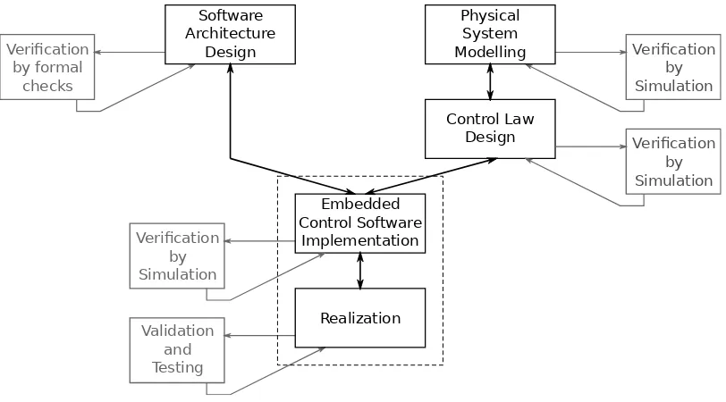
At the CE group, embedded control software is developed using the design trajectory as defined in Broenink et al. (2007), Broenink et al. (2010b) and Bezemer et al. (2011a), see Figure 2.2. The dashed box shows the steps in the design trajectory where this project applies to.
Control Law Design
Embedded Control Software
Implementation
Realization
Physical System Modelling Software
Architecture
Design Verification
by Simulation
Validation and Testing Verification
by Simulation Verification
by formal checks
[image:19.595.100.506.77.302.2]Verification by Simulation
Figure 2.2:CE design methodology (Broenink et al., 2010b)
Short description of the design steps: • Software Architecture Design
A software architecture is created to add high-level behavior to the embedded system. • Physical System Modelling
The interesting dynamic behavior of the system is modelled. • Control Law Design
For the dynamic model, loop controllers can be designed. • Embedded Control System Implementation
The controllers are implemented using (software) algorithms and are combined with soft-ware architecture.
• Realization
The complete collection of algorithms are converted into an executable to be run on a computing system.
The development routeSoftware Architecture Designand the routePhysical System Modelling
andControl Law Designcan be performed in parallel. All steps are clarified in the following sections.
2.7.1 Physical System Modelling and Control Law Design development route
For instance, bond graphs can be used to model a dynamic system and a simulator can be used to analyze the resulting system behavior.
20-sim (Controllab Products, 2011) is a graphical modeling and simulation tool for, among oth-ers, bond graphs. Using its Control Toolbox the controllers for the system can be designed and verified in its simulator.
2.7.2 Software Architecture Design development route
The CSP algebra, introduced by Hoare (1985) and Roscoe et al. (1997), can be used to reason about concurrent processes and patterns of communication between these processes. The al-gebra is based on a few simple constructs, such as denoting sequential or parallel execution of processes, and the rendezvous message passing paradigm. When two processes try to com-municate the first arriving processes, at this synchronization primitive, will be stalled until the second is also ready for communication. Thereafter, both processes can freely continue. A good introduction to Add "CSP" to dictionary can be found in Nissanke (1997).
As was already stated in the introduction, the graphical modeling tool gCSP (Jovanovic et al., 2004) can, for instance, be used to ease the development of CSP models. Note, this tool is an interpretation of the CSP algebra. During development the application can be monitored in gCSP through an animation facility (Steen, van der, 2008). Furthermore, the gCSP tool can generate code for the Failures-Divergence Refinement tool (Formal Systems (Europe) Limited, 2008) to formally check a design on deadlocks and lifelocks. Without such tools, the developing of complex concurrent software tends to become tedious and error-prone.
2.7.3 Embedded Control Software Implementation step
Along both development routes a design is made in a (graphical) modelling tool. These de-signs need to converted into code, such that the software architecture and controllers can be combined.
The 20-sim Code Generation Toolbox can be used to generate software algorithms of the con-trol laws.
The gCSP tool can generate code for the CTC++ library (Orlic and Broenink, 2004). The combi-nation of the CT library and gCSP is depicted in Figure 1.1. However, as was already stated in the introduction, the library cannot make use of multi-core/CPU architectures and its design is outdated. Therefore, the framework designed in this thesis will replace the CT library in the future.
Veldhuijzen (2009) reimplemented the CT library for the QNX OS. The main difference with the original library is that OS threads are used instead of user threads for CSP processes, and thereby multi core/CPU architectures are supported. Unfortunately, the approach to only use OS threads makes the CSP model execution slow (see Appendix I) and the implementation is not complete (apart from the basic processes).
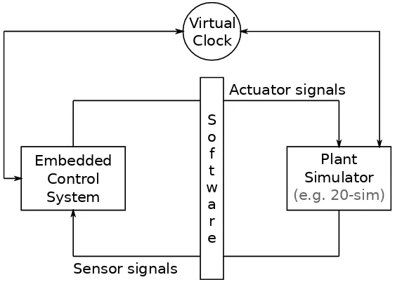
Plant Simulator (e.g. 20-sim) Embedded
Control System
Actuator signals
S o f t w
a r e Virtual
Clock
[image:20.595.144.425.527.728.2]Sensor signals
The combination of the software architecture and controllers can, for instance, be tested using co-simulation. Figure 2.3 schematically depicts such a test bench. The embedded control sys-tem hardware runs the combined software design, but generated actuator signals are routed to an off-target physical system simulator (e.g. 20-sim) instead of the actuators. The calculated physical states are send back to the embedded control software as sensory input. So, the test bench is created purely in software and the embedded control system does not use the actual physical system nor its actuator/sensor hardware. The virtual clock synchronizes the embed-ded control system and simulator execution, since simulating a complex physical system might take more time than running the application in hard real-time on its dedicated hardware.
2.7.4 Realization step
In the realization step, the generated software architecture and controller code is compiled into an executable for the target embedded system. This executable can then control the physical system. The complete system can be tested and validated by manipulating its inputs and veri-fying the generated output behavior or signals.
2.7.5 Embedded control software layers
Additionally for theSoftware architecture designstep in the design trajectory, a generic design pattern has been developed at the CE group, see Figure 2.4.
Embedded software I/O hardware Process
Soft
real-time real-timeHard Non real-time Meas. & Act. Actuators Sensors Power amplifier D/A
A/D Filtering/Scaling
Safety laye r Physical system Loo p co nt ro l Sequ ence control User in te rface Supe rvisory control & Interaction
Figure 2.4:Software architecture for embedded systems (Broenink et al., 2010a)
Each layer supports a type of real-time, varying from non real-time to hard real-time. The fol-lowing paragraphs discuss the common distribution for these.
TheLoop controlis the part of the application responsible for controlling the physical system and it is realised in hard real-time. If the loop controller fails to meet its deadlines for what-ever reason, the system is considered unsafe and catastrophic accidents might happen with the physical system or its surroundings due to moving parts.
In theSequence controlthe correct trajectory generator(s) and controller implementations are chosen based on the required action. The trajectory generator calculates the set-points for the
Loop controlto follow. Generally, this part of the application is more complex and requires more time to run its tasks than theLoop control. If a deadline is missed this is not immediately catastrophic, but some applications, like a wafer stage, might require hard real-time for this layer as well to guarantee smooth operation.
TheSupervisory control & interactioncontains algorithms which, for example, handle input events, map the environment, plan future tasks of the physical system or communicate with other systems. These might require soft or non real-time, depending on the application.
TheMeasurement & Actuationinterfaces with the hardware (directly). This usually means for-warding the signal values to and from the appropriate hardware registers.
TheSafety layeris used throughout the application to prevent unwanted control signal values.
3 Analysis
Before one can start to design a new system an analysis should be conducted to identify the expected problems, requirements and use cases. The purpose is to bring the final design and the expectations of the future customers as close together as possible. First a domain analysis will be performed and hereafter the requirements can be deduced from this. Although a use case analysis might be interesting, it is considered out of scope for this project.
The rest of this thesis will be based on the outcome of this chapter.
3.1 Domain analysis
The domain analysis is conducted to select the general field of business for the new frame-work and to get a better understanding of the challenges commonly present in the domain. Therefore, a domain analysis can improve the development time, system integration and an-ticipation of future extensions. Furthermore, it can help select implementation priorities.
The domain analysis for the new framework has been performed with four corner applica-tions selected from our laboratory. These are distinct set-ups commonly found in embedded (robotic) control research. The corner applications are:
• Jiwy - A small embedded control teaching aid.
• Production cell - An embedded distributed control application.
• Humanoid head - A control application focused on human-machine interaction. • TUlip - A complex humanoid walking robot.
These corner applications combined represent the total set of applications which are supposed to be realisable with the new framework. Note, all corner applications have already been re-alised and that the selected implementations all required an underlying operating system. It is also believed that these setups will resemble, at least, the near future embedded control soft-ware requirements. The results can be found in Appendix A.
An analysis into competing software has also been performed (Chapter 4), however with a slightly different approach than one might expect from a domain analysis. This analysis in-tends to identify other frameworks strong points and weaknesses, and concludes with remarks for the new design.
3.2 Requirements
The purpose of the requirements analysis is to define all functional and non-functional re-quirements the new framework should fulfill. Using the results from the domain analysis, the requirements can be deduced.
In the domain analysis both threads/processes and layers are used, but in fact layers can be seen, from an OS point of view, as a group of threads. Unless explicitly denoted, both can be used interchangeably.
3.2.1 Functional requirements
3.2.1.1 Platform independence
The framework should ultimatelysupport different hardware platforms and operating systems. For the first implementation the QNX OS on a x86 architecture was chosen. But, in the future also other target OSs (like RTAI and Xenomai) should be supported. If the chosen target OS supports them, different hardware architectures should be supported (like a PowerPC or ARM) as well. Furthermore, an OS-less version of the framework should in principle be possible in the future. Next to the mentioned target OSs, a few development OSs (like Windows and Linux) should be supported as well to facilitate development. So,the framework should be designed as platform independent as possible to enable future OSs and architectures.
3.2.1.2 Real-time constraints
The four corner applications all requirehard real-time constraintsfor, at least parts of, their application. Because of the limited available computing resource in the more advanced setups, it is necessary to specify amixture of hard/soft/non real-time constraintthreads in order to fulfill the timing requirements.
3.2.1.3 Thread support
To take advantage of multi-core/CPU target systems,OS thread supportis required. But, this should not cripple single core/CPU embedded systems.
3.2.1.4 Priorities
It is sometimes required tosubdivide a real-time constraint level into multiple smaller priority levels. Such that optimal timing results can be achieved.
3.2.1.5 Periodicity
Certain parts of robotic applications are required to exertperiodic behavior. In one application
multiple frequencies with each multiple threadsmay be present. Furthermore, the component implementing the periodicity should adhere the priorities and real-time constraints assigned to the thread.
3.2.1.6 Communication
A common approach in software design is to divide and conquer, which requires parts of a design to communicate with each other to exchange data or active one another. All four cor-ner applications are designed following this principle. Thus, the threads in an application will need tocommunicate with each other, with other applications on the same embedded computer or even on different hosts. Furthermore, thecommunication should conform to the real-time constraints and priorities assigned to the communicating threads.
3.2.1.7 Synchronization
Resources might be accessed concurrently. To ensure proper and safe operation thethreads and processes should be able to synchronize access to any software resource, which in turn can be used to protect hardware resources.
3.2.1.8 (Link) drivers to/from hardware
3.2.1.9 External code and/or library integration
The new framework should not reinvent the wheel and thereforeprovide mechanisms to in-clude external code and libraries. For example, one can think of the ROS (ROS, 2011) framework or the GSL (2011) library for performing advanced matrix calculations.
3.2.1.10 CSP execution support
For CSP models to run on the new frameworkCSP execution supportshould be added. Prefer-ably, with the same functionality as the current CT library offers.
3.2.1.11 Safety layer
To prevent hazardous situations for the setup and environment asafety layershould be present in all robotic applications. This layer mostly provideslimits on actuator output signals,takes action on endstop eventsand is sometimes used toidentify broken sensors.
3.2.1.12 Debugging facilities
Although applications and frameworks are preferred to work out-of-the-box, it is a good idea tosupply (standard) debugging facilities. These should also be used to generate bug reports for the framework developers, so that problems can be solved efficiently. Furthermore, it would be nice to have adebugging utility which does not influence the real-time constraints nor timing.
3.2.1.13 Self testing
The complete framework will most likely contain hundreds of classes and interfaces, whereby some only are available on specific platforms. Additionally, the framework might be used on platforms the developers even did not think of. Therefore it is wise to supply astandard self-test, which can be run on the intended platformto see if all required features are operational. This will also increase the confidence users have in the framework.
3.2.1.14 Reusable component specification and interconnection†
Parts of a robotic application might be reused in other parts of the application. In order to achieve this it would be beneficial if the framework could support a generic manner to perform: • Parameter configuration- dynamically loading and replacing of settings for a
compo-nent.
• Component interaction specification - stipulates how (repeated) components fit to-gether in an application.
• Flexible connections- communication vectors might vary in size depending on physical properties they represent, and some components might be able to provide generic oper-ations on these.
It is realized that the above definitions are very short, but they only serve to point out identified future work or, perhaps, these should be supported by a graphical tool.
3.2.1.15 Stepwise implementation support†
The divide and conquer approach in software design also applies well to implementing and testing the application (see Figure 2.2).
The proper working of the software architecture design can, for instance, be empirically verified by animating execution (of a special implementation version) in a graphical modelling tool. The software architecture implementation support provided by the new framework should be augmented with ananimation frameworkandmissing algorithms need to be replaced with mock-up algorithms.
physical robot, preventing possibly damaging the physical robot or the environment during application development.
In order to support co-simulated testing of complex physical systems, it should be possible to
seamlessly exchange the real-time clock with a virtual clock, because the simulator will most likely not be able to keep up with the real-time constraints of the application itself. Generally it takes time before a simulator has calculated the next physical state, while the application is designed to handle all computations for the real physical plant in a relatively short time. The virtual clock will take care that the application will only progress whenever new simulation data was received. Furthermore, theactuator output generated by the application should be (re)routed to the simulatorto update the simulated dynamic behavior and then the calculated
sensory outputs should be fed back to the applicationfor the next application cycle.
3.2.2 Non-functional requirements
The software design and the employed programming style should reflect the real-time con-straints. The normal case should be to design and program for hard real-time and if this cannot be achieved it should be documented.
Thesoftware design should be scalable. All kinds of setups should be controlled: From the big robotic humanoids to small embedded platforms with limited computing resources.
Interfaces should be easy to use correctly and hard to use incorrectly. People using a well-designed interface almost always use the interface correctly, because that’s the path of least resistance. Good interfaces anticipate mistakes people might make and make them difficult (ideally impossible) to commit.
Unify interfaces for components with similar operations as much as possible. For example, a simple communications protocol and a file writer could employ the samewritefunction to ‘send’ their data to their respective destinations.
The new framework should preferably befaster than the current CT library. Furthermore, it should givebetter or likewise timing results. A lesser performance would undermine its future position as the to-be-used framework for embedded control applications in the laboratory.
Example and test programs should be supplied with the framework, to provide a show case, aid learning how to use the framework properly and increase confidence in the framework.
Theframework interfaces should not be dependent on features which are not commonly avail-able. For example, Boost (2011) tuple functions are only usable when the framework is com-piled with Boost. Furthermore, such features might change overtime and render applications created with the new framework into legacy status.
3.3 Conclusions
The new framework will be able to control the aforementioned four corner applications and future applications, when the identified functional requirements are implemented. The corner applications represent the total set of embedded applications which are supposed to be real-izable with the new framework. Furthermore, a subset of the functional requirements is also implemented by the current CT library.
Requirements marked with a † are not considered in this thesis, but are highly recommended for implementation in the future. These will simplify development and enable iterative devel-opment and testing.
4 Framework and library research
The purpose of this chapter is twofold. First, state of the art embedded control libraries and frameworks will be investigated to determine if one can be found which already implements the requirements (Chapter 3). Secondly, which valuable lessons can be learned from these libraries and frameworks?
The introduction will first present all considered state of the art frameworks and libraries very shortly. Then a pre-selection will be made, which will narrow the investigative space to alluring frameworks and libraries regarding the purpose of this project. The approach section will then describe how the detailed research was conducted. Next, the selected frameworks and libraries will be discussed in detail. The last section will give a comparison between the discussed frame-works and libraries and concludes regarding the two-fold purposes of this research.
4.1 Introduction
The considered state of the art frameworks and libraries are ROS (2011), C++CSP2 (2009), Oro-cos (2011) and RoboFrame (2010). ROS is a framework for robot software development, provid-ing operatprovid-ing system-like functionality on top of a heterogeneous computer cluster. C++CSP2 is a framework for CSP based algorithm execution. Orocos deals with the definition of compo-nents. RoboFrame is a message oriented middleware, which thus deals with the communica-tion between modules or layers.
Framework Hard real-time Platform independence
ROS -
-C++CSP2 -
-Orocos + ++
RoboFrame +/- +
CT (CTC++) + +
Table 4.1:Generic framework characteristics
Table 4.1 presents the basic characteristics of the aforementioned frameworks.++is the max-imum achievable score and−−is the lowest achievable score. A framework is hard real-time when it adheres to real-time programming restrictions (for details see Section 5.1.5). A frame-work is platform independent when it provides methods to abstract the OS specific system calls. On the basis of these results a pre-selection will be made.
To be clear, when a framework provides POSIX compliance this does not mean that it will be hard real-time by definition on a hard real-time OS like QNX. Only if the real-time programming restrictions are followed it can be hard real-time. Furthermore, if the framework/library does not explicitly state it is designed for hard real-time nor provides an implementation for at least one hard real-time OS other than POSIX compliant ones, it is assumed to be soft real-time at best.
The C++CSP2 library, which actually is a framework, provides a multi-threaded CSP engine. Unfortunately, it is not suitable for hard real-time applications controlling setups. Because, it actively makes use of C++ language exceptions to influence the execution flow, which make an application in general non deterministic (see Appendix B). Additionally, the framework does not have any means for platform independence. Therefore the C++CSP2 framework is not con-sidered any further in this chapter. However, the C++CSP2 library was consulted during the CSP component development for the new framework.
Orocos is advertised as a hard real-time framework, but as will be shown in section 4.3 the framework is most likely not able to perform well enough for loop control nor implementing CSP constructs, due to its considerable software footprint. The framework supports multiple OSs, with among others RTAI.
The RoboFrame framework is not designed for real-time, but the extension explained in Sec-tion 4.4 can be used to perform loop control in robotic applicaSec-tions. Furthermore, its separa-tion in modules and platform independence make it worthwhile to investigate.
As explained before, the CT library is build for hard real-time execution of gCSP generated code. However, due to its inaccurate timing, it does not get the full++score for hard real-time. Al-though the framework supports multiple OSs (among others RTAI), the tight integration be-tween CSP and the platform abstraction is not desirable and results in a+.
The table shows that none of the considered frameworks is truly hard real-time (i.e. a++in this column), which is an integral requirement for the new framework. So, together with the fact that the current CT library is outdated, it can be concluded that the design of a new framework is a viable choice.
Because no suitable framework is found, one could choose to build a new framework with the aid of state of the art libraries, such as Boost (2011) or POCO (2011). The Boost C++ libraries are a collection of free libraries that extend the functionality of C++. It is aimed at a wide range of C++ users and application domains. POCO also is a collection of open source C++ class libraries and frameworks, but is targeted at building network and internet based applications that run on desktop, server and embedded systems.
Library Hard real-time Platform independence
Boost +/-
+/-POCO +/- +
Table 4.2:Generic library characteristics
Table 4.2 presents the basic characteristics of the aforementioned libraries. The scoring system is the same as for the framework comparison.
Any proposed library should also be C++ language exception free, to achieve the real-time con-straints. Unfortunately, both libraries actively use them to handle exceptional circumstances.
4.2 Approach
Most frameworks and libraries supply software manuals for the end user, which is considered good practice of course. Unfortunately, only Orocos has a manual for developers detailing its inner workings, which is what we are interested in. All frameworks also have papers published about them. But, even with all these resources some questions could not directly be answered. Therefore, to fully understand what makes the considered frameworks so good and what makes them tick, reverse engineering and code inspections were also performed.
Naturally all frameworks and libraries will have their own applications and boundary condi-tions. The introduction of each subsection presents these among others. Furthermore each framework and library will have the following subsections:
• General software architecture- presents the general idea behind the framework/library. • Platform independence- discusses how platform independence is solved.
• Timing and real-time capabilities- deals with these specific aspects.
• Scalability and extensibility- comments on the scalability and extensibility, with respect to embedded system usage and building the new framework with it.
The introduction and general software architecture are fact based presentations on the specific framework/library. The other sections may also contain discussions on the subject at hand. Furthermore, these subsections roughly fit the requirements specified in Section 3.2.
4.3 Orocos
The Open RObot COntrol Software1(Orocos) is the most extensive robot and machine control software currently on the market. The Orocos project supports four C++ libraries: the Real-Time Toolkit (RTT), the Kinematics and Dynamics Library (KDL), the Bayesian Filtering Library (BFL) and the Orocos Component Library (OCL). The libraries are open source and can be freely downloaded, used and distributed (Orocos, 2011).
The Real-Time Toolkit (RTT) is not an application in itself, but provides the infrastructure and the functionality to build robotic applications in C++. The emphasis is on real-time, on-line in-teractive and component based applications. Only this library will be discussed in this chapter, but for completeness the other libraries will be introduced briefly. The Orocos Components Li-brary provides some ready to use control components. The Orocos Kinematics and Dynamics Library is a library to calculate kinematic chains during run-time. The Orocos Bayesian Fil-tering Library (BFL) provides an application independent framework for inference in Dynamic Bayesian Networks, i.e., recursive information processing and estimation algorithms based on Bayes’ rule, such as (Extended) Kalman Filters, Particle Filters and more.
Figure 4.1:Orocos framework overview (source: Orocos, 2011)
4.3.1 Software architecture
The Orocos project focuses on component based applications with fixed interfaces. For the component specification these interfaces are systematically separated in Computation, Com-munication, Configuration and Coordination (4C’s). The components are build on top of the RTT framework (see Figure 4.1), which provides the infrastructure and the means for execution.
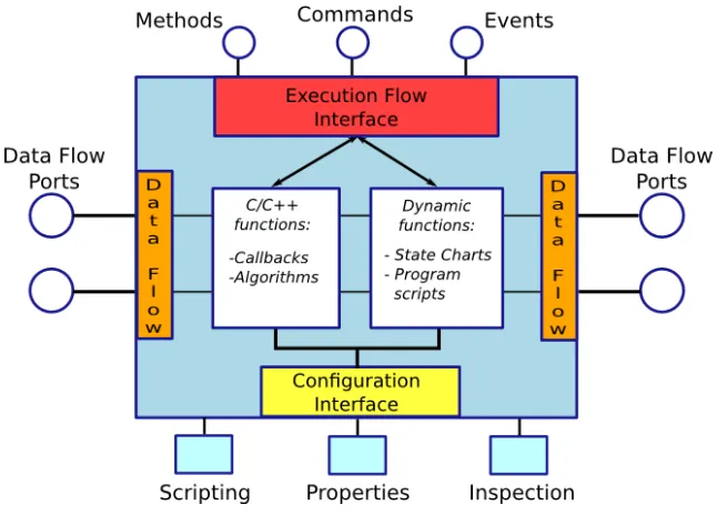
Each component is defined as aTaskContext, which defines the environment or ‘context’ in which an application specific task is executed. TheTaskContextinterface provides five public manipulation methods:
• Attributes and properties
The attributes and properties in aTaskContextcan be used to get and set configuration data. Attributes are plain variables which expose C++ class members to the scripting layer, additionally properties can be stored to and loaded from an XML file. The reading and writing of properties and attributes is not thread-safe.
• Methods
Methods resemble normal C++ functions, i.e. they are directly executed by the caller, but they also can be called from a script or over a network connection. Calling methods is, as in C++, not thread-safe.
• Commands
Commands are asynchronous function calls, with respect to the caller, and they are ex-ecuted in the receiver’s thread. Furthermore they might be queued and must provide a boolean value to indicate success or not. Commands are thread safe with respect to other RTT processors (discussed in the RTT Execution section) running in the receiving compo-nent.
• Events
Events are designed according the classic publish-subscribe software pattern (Douglass, 2002), i.e. one ore more clients can register their callback functions for a specific event. When the event is raised, the connected functions are synchronously or asynchronously called one after the other. Publishing and reacting to an event is thread-safe only in asyn-chronous callbacks. A task may register its events in its interface in order to be used by its state machines and other tasks as well. Unfortunately, it cannot be predicted when the event is executed.
• Data-Flow ports
A stream of data can be send between tasks using a data-flow port. This data can be passed buffered or unbuffered and a task may be woken up if data arrives or it can use a polling scheme to check for new data at one of its ports. The data-flow ports are connected using a modified Acceptor-Connector software pattern (Douglass, 2002), which decouples the connection and communication roles. The data-flow ports could for example be used to implement a classic control loop. Reading and writing data is thread-safe.
Furthermore, the TaskContext internals provide a build-in state machine, which can be ex-tended through various C++ function hooks (e.g. updateHook()). The internal state machine will be explained in the RTT execution section.
The class TaskContext groups all these interfaces and serves as the basic building block for components. TheTaskContextis schematically shown in Figure 4.2.
Dynamic program flow
An Orocos component (TaskContext) can have a dynamic program flow via: • Real-time scripts
• User defined state machines
Figure 4.2:OrocosTaskContext(source: Orocos, 2011)
The real-time scripts and user defined state machines will be discussed in the RTT execution section. The CORBA package enables Orocos components in separate processes and possibly distributed over a network connection to communicate with each other. This part of the RTT is considered out of scope and will not be discussed any further.
RTT Execution
[image:31.595.140.463.77.309.2]The execution of aTaskContextis performed by theExecutionEngine(see Figure 4.3). An Exe-cutionEngineshould be added to aPeriodic-,Nonperiodic- or plainActivity, which ever is suited best according to its periodicity requirements. The different Activities map onto different op-erating system threads and these may hold multipleExecutionEngines with the same real-time constraints. TheExecutionEngines contained in aPeriodicActivity are executed exactly once per period. Furthermore, if an overrun of thePeriodicActivityoccurs this is recorded and can be dealt with accordingly.
The commands, events and internal state machine of theTaskContextinterface are executed by theExecutionEngineusing, so called, processors. Furthermore, the real-time scripts and user defined state machine are also executed by a processor. These five processors are executed in the order they are explained next:
• Real-time scripts -ProgramProcessor
The Orocos scripting language enables users to write programs and state machines for controlling the system in a non hard-coded manner. The advantage of scripting therefore is that it does not need recompilation of the main program and, according to the Orocos project team, makes the Orocos components easily extensible. The disadvantage is that it decreases system performance, as scripts needs to be interpreted, and may violate hard real-time constraints as will be discussed in Section 4.3.3.
The scripting language supports, among others: variables, constants, if-then-else, for-loops, while-for-loops, function declarations and interfaces to the other processors. Recur-sive function invocation is prohibited, since this results in non real-time behavior by def-inition.
• User defined state machines -StateMachineProcessor
The component designer may add his own state machine to theTaskContext. This state machine has (conditional) edges and may emit commands to its own or other TaskCon-texts. A state machine can run in two modes: automatic mode and the reactive (also ‘event’ or ‘request’) mode, which can be switched at run-time. To be clear, this state ma-chine is not part of the internal state mama-chine which provides function hooks.
The program and state machine scripts share the common syntax and semantics, addi-tionally the state machine also provides extra functionality to specify states, precondi-tions for state entry and (conditional) edges. The script parser is strongly typed and if a run-time error occurs, i.e. if a statement fails, it will bring theTaskContext’ state machine into the error state.
• Commands -CommandProcessor
The (buffered) commands are sequentially executed by the CommandProcessor. • Events -EventProcessor
The asynchronous (buffered) events are executed sequentially by the receiving TaskCon-text’s EventProcessor.
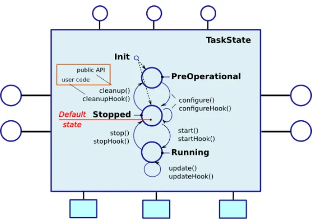
• Internal state machine - by theExecutionEngineitself via, for instance,updateHook()
For implementing algorithms theTaskContext provides an internal fixed state machine, which should be extended in C++ function hooks to initialize, configure, start, update, stop and clean-up a component. The basic state machine without exceptions is shown in Figure 4.4.
Methods, data-flow ports, properties and attributes are not executed by any processor, because methods operate in the calling thread directly on aTaskContext’s internals. Data-flow ports may raise events or call the execution engine to process the newly arrived data. The attributes and properties can be manipulated from theProgramProcessor,CommandProcessor, EventPro-cessoror internal state machine.
Figure 4.4:Orocos internal state machine (source: Orocos, 2011)
TheExecutionEngineprocessors for aTaskContext are thread safe with respect to each other, since they are run one after another in oneActivity. Furthermore, the sequence of program ac-tions is serializable, because allExecutionEngineprocessors on an Activity run in a predefined order.
4.3.2 Platform independence
Components interact with the underlying operating system and other components through the Real-Time Toolkit, see Figure 4.5. The RTT is a platform independent layer that provides inter component communication, (a)periodic threading, mutexes & semaphores, data streams, time related operations (e.g. sleep), networking, property management through XML files and some general operating system calls. Furthermore the RTT specifies an interface for generic data acquisition and (actuator) drivers.
The platform independent RTT features have a generic interface and implementation. The im-plementation is composed of functions with a generic function signature, which is the same for all supported platforms. Macros then include the right OS dependent header, i.e. function skin, which contains the actual function implementation. The use of macros in general is not preferable, because one needs to actively keep track of them and problems with macros some-times are hard to track in sources. For the currently maintained OSs the function skin approach worked out well, but these functions might not match well when building support for a new OS.
The Orocos RTT is currently maintained for RTAI (Linux) and Xenomai (Linux) real-time oper-ating systems and the general purpose operoper-ating systems plain Linux, Mac OS X and Windows. Additionally, Orocos provides a device driver abstraction layer.
4.3.3 Timing & real-time capabilities
Figure 4.5:Orocos software design overview with respect to platform abstraction (source: Orocos, 2011)
framework with setpoints. Therefore, the framework basically is operating at a soft real-time level, since it does not matter if a setpoint arrives slightly late at the hardware control loop.
In our group we like to design the control loops ourselves and are not using such hardware control loop solutions. Furthermore, it is impossible to use formal methods to confirm that a complex application, build using Orocos, is deadlock or livelock free, because of the size and complexity of the framework (Dijkstra, 1972).
Fortunately, Orocos does provide means to determine, at run-time, if an overrun of a periodic task occurred and also provides some failsafe mechanisms for it. But, this is a run-time feature and therefore will not guarantee proper nor safe operation for a robotic application.
Real-time scripts
Real-time scripting, in general, should be looked at sceptically. Because, for a scripting sys-tem to be real-time it has to adhere to the same conditions as normal code, i.e. it should have deterministic timing. But, the commonly accepted method for parsing scripts is to incur mul-tiple layers of abstraction which have to be passed through before, for example a statement is accepted. Note that different types of statements possibly have different layers of abstraction. Furthermore, certain commands in a script might want to allocate memory, which in most sys-tems is not a deterministic operation.
4.3.4 Scalability & extensibility
Orocos components can be used in both embedded or general purpose systems, depending on the application design. The placement of multiple components and the specification of their interconnections on a specific target is called component deployment in Orocos.
Three distribution levels of component deployment can be realized in Orocos: • Not distributed
In case the application will not use distributed components and a very small footprint (< 1 MB RAM) is required, the TaskCore should be used. The TaskCore is a base class of the previously explainedTaskContextclass, and provides the manipulation methods in a hard coded non-dynamic manner (i.e. no scripts and user defined state machines).
• Embedded distributed
In case the application requires a small footprint and distributed components the
TaskContextin combination with the distribution library, which does the network trans-lation, can be used. TheTaskContext, in this manner, can only handle a predefined set of build-in data types and requires modification if other data types should be supported. • Fully distributed
If the application footprint is of no concern and components should be distributed com-pletely transparently, theTaskContextin combination with a remoting library, for network translation, can be used. The Orocos developers are working on a CORBA implementa-tion for this, which can pick up user defined types without requiring modificaimplementa-tions. The components designed with the embedded and fully distributed deployment interfaces can be dynamically configured from an XML file.
Unfortunately the three distribution levels require different implementations because of their interfaces. A component, developed for one distribution level, therefore cannot be used on an-other without modification. Lootsma (2008) has also pointed out that the Orocos RTT frame-work can be quite resource consuming. This is, actually, not a surprise if one takes into account the large number of manipulation methods and execution flow solutions.
Due to its size the Orocos framework is not suitable to implement CSP constructs on a low level, but it would be possible to build a standard OrocosTaskContextfor running or interfacing with a complete CSP model.
4.4 RoboFrame
RoboFrame2is a modular software framework for lightweight autonomous robots, created by the Technical University of Darmstadt. RoboFrame started as a master thesis project of Petters and Thomas (2005). It addresses the needs of heterogeneous teams of autonomous lightweight robots and it is used for example in the robot soccer competitions.
The framework has been designed to facilitate reuse of its architecture in many different sets o