The Study of Various Control Techniques and Configurations for Grid
Connected Photovoltaic DC/AC Converter
Shyam P. Zarikar
1, Mrs. M.R. Bachawad
21
M.E. (Electrical Power System), Government College of Engineering, Aurangabad
2
Associate Professor, Department of Electrical Engineering, Government College of Engineering, Aurangabad
---***---Abstract - The fossil fuels are unable to meet energy demand thus requirement of the grid connected photovoltaic system arises which increases the importance the DC/AC converters. Hence the study of control strategies employed on it needs to be studied to enhance performance and efficiency. This paper discuss about different topologies, international grid standard, power processing stages in system, MPPT, challenges and the control strategies for converter. A review is done on control strategies for converter (AC and DC side). Also a comparative analysis is done between different strategies.
Key Words: PV system, Inverters, Grid Standards, MPPT,
Current control techniques
1. INTRODUCTION
The thrust to reduce pollution and green house gases generating from the thermal power plants, Renewable energy sources has gained significant importance as a new source of energy to meet the growing demand of energy [1]. India is country where the solar radiation is received in huge amount. The solar radiation received in the country per year is equivalent to 5100kWh that is greater than the annual energy requirement of the country. The estimated renewable power generation as on 31.03.2017 is 10, 01, 132 MW in India which constitute solar power of 649342 MW i.e. 64.86% of total power. The total installed capacity of grid connected renewable sources, which was 42849.38 MW as on 31.03.2016, had gone up to 57244.23 MW as on 31.03.2017 which shows the increment of 33.59% during period. Solar power is around 21.47% out of total installed generation capacity of renewable power as on 31.03.2017 [2].
The growth in installation of grid connected PV system increase due to incentives and support given by the Government. Thus, it becomes necessary to study the control strategies employed in grid connected solar photovoltaic systems. As grid connected PV inverters deals with alternating current mode and direct current mode, the control of both AC side or grid side and DC side or PV side comes into picture. Out of both controls DC side control is simpler than AC side control.
2. CONFIGURATION OF GRID CONNECTED PHOTOVOLTAIC (PV) INVERTERS
The grid connected PV inverters have different configuration that can be categorised in three types, the
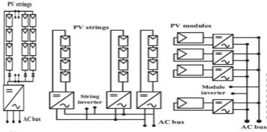
central inverter topology, String topology and Module topology [3]. The three types are explained below with their advantages and disadvantages. Also they are shown in following figure (1)
Fig -1: Configuration of PV Inverter
In the design of central inverter topology to increase voltage rating a number of PV modules are connected in series and these series connected PV modules are commonly referred as String. By using string diodes, power level can be increased by connecting strings in parallel. Then interconnected PV module is connected to centralised inverter to main grid [3-4]. The central inverter topology have some disadvantages such as: (a) losses due to voltage difference (b) losses among PV modules and losses in string diodes (c) interconnection between inverter and PV module needs high voltage DC cable. (d) In this topology line commutated thyristors are used which provides current harmonics and poor power quality [4-6]
[image:1.595.313.586.268.403.2]Table -1: Comparison between topologies
Topology Central String Modular
Power
Rating 1-50 MW 1-5 kW per String 500-600 W Advantages 1.Lower cost
2.Robust 3.Easy maintenance
1. String diode losses eliminated 2.Decent Consistency 3.Flexible design & Structure 4.Reduction in partial shading energy
1. Each panel can be optimally tracked
2. No
mismatch loss between modules 3.flexible to expand design
Disadvantag
es 1.Mismatch lossesare high 2.Low
reliability
1.Suitable to low power rating 2.Sensitivit
y of
Inverter increases
1.Low efficiency 2.Difficult maintenanc e
Usage Residential
applications Large Power plant Application
Not generally used.
2. DIFFERENT INVERTER TOPOLOGIES
Depending upon components and configuration used, inverters are classified in various categories. This differentiation is based on the factors like number stages power processing has and transformer connection. Each category is briefly explained as below:
2.1 Depending Upon Power Processing Stages
This category is again sub divided into two types those are single stage and multistage inverter which are described below:
In a single stage inverter system, the inverter has to do various tasks such as control of grid current, maximum power tracking and amplification of voltage if needed. In a single stage converter design, it has to handle twice the peak power. As shown in following equation:
(1)
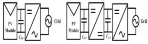
Where ωgrid is frequency of grid and Pgrid is the peak grid power. Following is the block diagram for single stage inverter shown in figure (2)[10-11].
Fig -2: Single stage Inverter
An inverter design having power processing stages more than one is called as multi stage inverter. The most common arrangement for any multistage inverter contains two stages of power processing. One is DC-DC converter and another is DC-AC converter (inverter) [12]. As shown in following figure (3):
Fig -3: Multi stage Inverter
In such type of inverter first stage performs voltage amplification while in second stage it converts DC into the AC. To wipe out the voltage spikes and pass on the DC component of PV source, power decoupling is needed in single stage as well as multi stage inverter. A decoupling is done by using a electrolytic capacitor of higher capacitance. There are two ways of placing the capacitor in the system. One is parallel to PV module and another as a DC link in between two converter stages [13-14]. The capacitor link is shown in below figure (4) [4].
Fig -4: Capacitor Link Connection
The purpose of the inverter in system is the conversion of power from DC to AC at high switching frequency. Thus, functioning at such higher switching frequency results into unwanted switching transients. These transients are blocked by DC capacitor link from moving in backward direction to protect PV module. But at higher temperature capacitor’s life is less as compared to other components in inverter also the cost and bulky size are some disadvantages of the capacitor. Research is going on small film capacitor as an alternative [15].
2.2 Transformer and Transformerless Inverters
[image:2.595.30.292.118.449.2] [image:2.595.315.553.261.337.2] [image:2.595.322.567.484.558.2]module line frequency transformers are used also it helps for galvanic isolation between grid and PV module. But line frequency transformers are large in size which raises the overall cost of the system [3-4]. Whereas, transformerless topology is, cost effective with higher efficiency compared to transformer based topology. To deal with DC injection problem separate circuitry need to be installed in transformerless inverter topology.
3. International Grid Standards
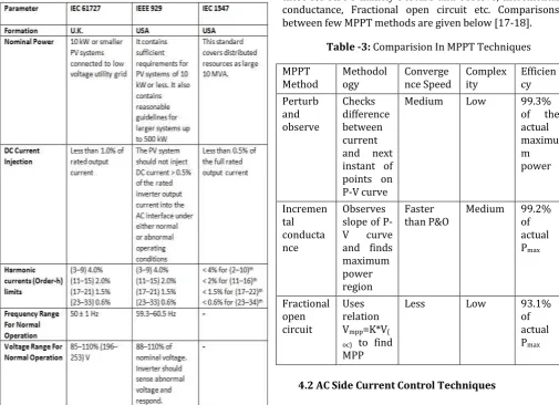
Below table shows international grid standards [10].
Table -2: Grid Standards
4. Control Schemes For DC/AC Converter
For grid connected inverter, control strategies need to be employed on two parts i.e. control for dc side (PV module) and control for AC side (grid). In order to extract maximum amount of power from the power module MPPT technique is widely used on the DC side. For AC side control different types of current controllers are used for synchronisation with grid. MPPT and different controllers are discussed below in briefly.
4.1. DC Side Control Using MPPT
[image:3.595.53.559.265.631.2]There is a difference between the mechanical tracking (sun tracking) and MPPT of solar PV modules. In the case of mechanical tracking, we mechanically rotate PV modules in order to intercept maximum radiation by the module (hence maximizes power generation) under a given condition, But in MPPT, There is no need of mechanical rotation of the PV module; this part is carried out by the electronic circuit. The MPPT mechanism uses an electronic circuitry and an algorithm. The MPPT mechanism is depends upon on the principle of impedance matching between the load and PV module, which is essential to transfer the maximum power [16]. Different Methods are there for MPPT namely Perturb and observe, Incremental conductance, Fractional open circuit etc. Comparisons between few MPPT methods are given below [17-18].
Table -3: Comparision In MPPT Techniques
MPPT
Method Methodology Convergence Speed Complexity Efficiency Perturb
and observe
Checks difference between current and next instant of points on P-V curve
Medium Low 99.3%
of the actual maximu m power
Incremen tal conducta nce
Observes slope of P-V curve and finds maximum power region
Faster
than P&O Medium 99.2% of actual Pmax
Fractional open circuit
Uses relation Vmpp=K*V( oc) to find MPP
Less Low 93.1%
of actual Pmax
4.2 AC Side Current Control Techniques
4.2.1 PI Current Control
The PI controller is part of the classical controller’s family. This family consist of proportional integral derivative (PID), Proportional controller and Proportional derivative (PD) controllers. The proportional part of the PI controller is related to reduce the ripple or transients while integral part is related with the minimization of the error. The proportional controller’s steady state error is minimized by adding an integral component to a transfer function. The error signal is generated by comparing output current of the inverter with the reference current obtained from grid voltage. Then error signal is controlled by PI controller. The control signal from PI controller is then compared with triangular signals with constant switching frequency is used for obtaining PWM pulses [19]. The advantages of PI controllers are: less effect of DC side ripple on AC output waveforms of inverter and reduction in steady state error[20]. The typical block diagram of PI current control is shown below:
Fig -5: PI Controller
4.2.2 DQ Current Control
The current control gets easy when we convert AC component of current into DC. Using Clark’s transformation three phase AC current component can equivalently converted into DC component.
Tracking controllers used for AC component of current are more complex than Set Point controllers used for DC components. So in DQ current control three phase AC components of currents are transformed into two DC components namely d and q, which 90° apart from each other. Application of PI controller is there in dq control. Here as shown in figure (6)
Fig -6: dq Control Strategy
4.2.3 PR Resonant Control
The implementation of the control technique is much simpler in PR compared to dq0. PI and PR controllers works in similar manner but they operate in two different operating frame. PI controller is efficient in tracking DC component while PR controllers are good in tracking AC signals. The integration take place in PI and PR are different. In PR controller integrator integrates frequencies which are closer to resonant. Harmonic compensation in PR controller is poor [20].
4.2.4 Hysteresis Controllers
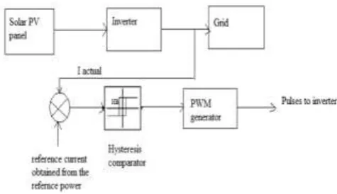
Hysteresis control is one of the non linear current control techniques. It is simple and robust control technique. An adaptive band of controller must create to attain stable switching frequency, which is necessary step for the implementation of the hysteresis controller [21]. Following is the block diagram for the hysteresis controller implemented to grid connected PV system.
Fig -7: Hysteresis Control Technique
4.2.5 Sliding Mode Control
[image:4.595.316.559.69.256.2] [image:4.595.40.284.339.514.2] [image:4.595.323.561.531.668.2]Advantage of sliding mode control technique is it’s insensitivity towards parameter changes and load disturbance. Thus it is suitable for time varying system. It regulates system to follow trajectories defined by sliding surface which is similar to hysteresis band in hysteresis controller. To work system in desired manner, system has to be in equilibrium state. For design of sliding mode control three elements are necessary: sliding surface, equivalent control and selecting non linear control input to meet Lyapunov stability criterion [22].
4.2.6 Modified Ramp Control
In this control phase shift error is absent because phase shifter is used in it. A comparison is done between triangular waves and error signal. Triangular waves are of constant amplitude and frequency while error signals are derived from current controller. It is a non linear current control technique.
4.2.7 Predictive Controllers
With use of system model, predictive controllers predict the future response of the controlled parameters. Although it is easy in implementation it has more number of calculations than PI or PID controllers. Deatbeat controller is type of predictive controller. In which error is nullified at end of each cycle by selecting proper voltage vector. Model predictive controller (MPC) is also one of the types of predictive controllers.
4.2.8 Current Regulated Delta Controller
In this controller the switching frequency can be controlled desirably by using latching device. This controller is same as hysteresis controller except latching device. The latching device can enable by using clock signal.
4.2.9 Direct Power Control
In conventional direct power control method, three phase quantities are converted into dq axis frame and by using current control loop active and reactive power was derived. But in direct power control method using sliding surface three phase abc vectors transformed into αβ stationary reference frame. Then actual power is calculated using following equations
P(actual) = -1.5(VgαI gα + VgβI gβ) (2)
Q(actual) = -1.5(VgβI gβ - VgαI gα) (3)
The actual value of power is compared with reference value. Then state variable of sliding surface F is calculated with respect to power P and Q [3][23]. After that Vg is calculated using following equation
Vg = (1/D)[( Fp + Kp1sgn(Sp) + Fq + Kq1sgn(Sq))] (4)
Finally using pulse width modulation, gate pulses are given to inverter. The advantage of this method is fast dynamic response.
5. Conclusion
The fossil fuels are getting vanished, so research and development in field of renewable energy sources is necessity of a time. In this paper we discussed that India is a country which is blessed with abundance of solar radiation. To extract energy from solar radiation we discussed, different formation of photovoltaic modules, different topologies of inverter and international grid standards. We also studied the importance of transformer in grid connected photovoltaic system and advantages and disadvantages of number of power processing stages in the PV inverter grid connected system. The MPPT is widely used technique to extract maximum power from PV modules. The current controllers are divided into linear and non linear current controllers. We reviewed the controllers briefly with their block diagram, advantages and disadvantages. So connecting PV inverters to grid requires selection of proper current controllers and also proper implementation of the MPPT techniques. Increasing efficiency of PV panels, reducing cost of the overall system and eliminating maximum of harmonics generated by switching operation of converters can be the future scope.
6. REFERENCES
[1] Hui Zhang, Hongwei Zhou, Jing Ren, Weizeng Liu,
Shaohua Ruan and Yongjun Gao, “Three-Phase Grid-Connected Photovoltaic System with SVPWM Current Controller”, IPEM 2009.
[2] Energy Statistics, 25th issue, Central Statistics Office, Ministry of Statistics and Programme Implementation, India, 2018, pp. 03-11.
[3] Sivasankari Sundaram, K. N. Sheeba, and Jakka Sarat
Chandra Babu, “Grid Connected Photovoltaic Systems: Challenges and Control Solutions - A Potential Review”, International Journal of Electronics and Electrical Engineering Vol. 4, No. 6, December 2016.
[4] Kamran Zeb, Waqar Uddin, Muhammad Adil Khan,
Zunaib Ali, Muhammad Umair Ali, Nicholas Christofides, H.J. Kim, “A comprehensive review on inverter topologies and control strategies for grid connected photovoltaic system”, Renewable and Sustainable Energy Reviews 94 (2018) 1120–1141.
[5] Haeberlin H., “Evolution of inverters for grid
connected PV-systems from 1989 to 2000”. In: Proceedings of the 17th European photovoltaic solar energy conference.Munich, Germany; Oct. 22–26 2001. p. 426–30.
Conference recreational IEEE-IAS annual meeting, vol. 2; 2002. p. 782–8.
[7] Meinhardt M, Wimmer D, Cramer G.,
“Multi-converter: the next step in evolution of string-converter” In: Proceedings of 9th EPE, Graz, Austria; 2001.
[8] Calais M, Myzrik J, Spooner T, Agelidis VG., “Inverters
for single-phase grid connected photovoltaic systems—an overview” Proc IEEE PES’02 2002;2:1995–2000.
[9] Cramer G, Toenges KH. “Modular system technology
(string inverters) for grid connected PV systems in the 100 kW–1 MW power range” In: Proceedings of the 12 symposium photovoltaische sonnenenergie. Staffelstein, Germany; 1997.
[10]Mohsin Noman Mustafa, “Design of a Grid Connected
Photovoltaic Power Electronic Converter” MSc. Thesis, The Arctic University of Norway.
[11]Sachin Jain, Vivek Agarwal. “A single-stage grid
connected inverter topology for solar PV systems with maximum power point tracking” IEEE Trans Power Electron 2007;22(5).
[12]Saha S, Sundarsingh VP. “Novel grid-connected
photovoltaic inverter” Proc Inst Elect Eng 1996;143:219–24.
[13]Madouh Jamal, Ahmed Nabil A, Al-Kandari Ahmed M. “Advanced power conditioner using sinewave modulated buck-boost converter cascaded polarity changing inverter” Int J Electr Power Energy Syst 2012:280–9. [ISSN 0142-0615].
[14]Jana Joydip, Saha Hiranmay, Bhattacharya Konika Das. “A review of inverter topologies for single-phase grid-connected photovoltaic systems” Renew Sustain Energy Rev 2017;72:1256–70.
[15]Ahmed NA, Lee HW, Nakaoka M., “Dual-mode time –
sharing sinewave-modulation soft switching boost full-bridge one-stage power conditioner without electrolytic capacitor DC link” IEEE Trans Ind Appl 2007;43(3):805–13. [May-June].
[16]Chetan singh solanki, “Solar Photovoltaics-
Fundamentals, Technologies and Application”, second edition, pp 380-384.
[17]S. Jain and V. Agarwal, “Comparison of the performance of maximum power point tracking schemes applied to single-stage grid-connected photovoltaic systems,” IET Electric Power Application, vol. 1, pp. 753-762, 2007.
[18] D. P. Hohm and M. E. Ropp, “Comparative study of
maximum power point tracking algorithm,” Progress in Photovoltaic Research & Application, vol. 11, pp. 47-62, 2002.
[19] J. Selvaraj, N. A. Rahim, and C. Krismadinata, “Digital
PI current control for grid connected PV inverter,” in Proc. IEEE International Conference on Industrial Electronics and Applications, Singapore, 2008, pp. 742-746.
[20] H. Mojgan, A. Zaharin, A. Toudeshki, and M.
Soheilirad, “An overview on current control techniques for grid connected renewable energy systems,” in Proc. International Conference on Computer Science and Information Technology, 2012, vol. 56, pp. 119-126.
[21] N. A. Rahim, J. Selvaraj, and C. Krismadinata,
“Hysteresis current control and sensorless MPPT for grid-connected photovoltaic systems,” in Proc. IEEE International Symposium on Industrial Electronics, 2007, pp. 572-577
[22] I. S. Kim, “Robust maximum power point tracker
using sliding mode controller for the three-phase grid-connected photovoltaic system,” Solar Energy, vol. 81, pp. 405-414. 2007.
[23]J. Hu, L. Shang, Y. He, and Z. Q. Zhu, “Direct active and