Vol.7 (2017) No. 5
ISSN: 2088-5334
The Analysis of Stub on Coplanar-Fed of Single and Array Microstrip
Antenna for Mobile Satellite Communication
Muhammad Fauzan Edy Purnomo
#1,*2, Onny Setyawati
*3, Hadi Suyono
*4, Rini Nur Hasanah
*5,
Panca Mudjirahardjo
*6and Rahmadwati
*7#
Electrical Engineering and Computer Science, Kanazawa University, Kakuma-machi, Kanazawa, Ishikawa 920-1192, Japan *Electrical Engineering Department, Brawijaya University, Malang 65145 Indonesia
E-mail: [email protected]#, [email protected] #, [email protected], [email protected], [email protected], 6
[email protected], [email protected]
Abstract— The microstrip antenna has small, lightweight shape characteristics, and limit performances. It is necessary to increase the performances, especially the axial ratio (Ar) of the previous antenna configured in two layers accompanying the capacitive coupling between them. If length of feeding line and width-to-length ratio of radiating patch are not matched, it can decrease the Ar performance. This paper discusses about the analysis of previous antenna (two layers) and modified antenna (one layer), optimized modified antenna using stub on coplanar-fed both single and array microstrip patch antenna for mobile satellite communication, especially for receiver antenna, Rx. The Method of Moment (MoM) is used to analyze the antenna with an infinite ground plane and substrate. The antenna is made of a thin patch conductor and a microstrip-line. The microstrip-line is located on the same layer which has the thickness h = 1.6 mm and uses a conventional substrate (relative permittivity, εr = 2.17 and loss tangent, δ = 0.0009). The patch conductor is fed by a coplanar-fed with microstrip-line to obtain a conformal configuration. The dual-fed type is to generate a left-handed circular polarization (LHCP) which is combined with an equilateral triangle patch. In this case, one of the microstrip-line feeds is set longer than the other to introduce a 900 phase delay. Moreover, the simulation results discuss about the three varies size of stub embedded on coplanar-fed and compare among of them to confirm that the antenna satisfy the target. The results of single antenna using stub-fed, especially for bandwidth of axial ratio below 3-dB and gain above 5 dBic are about 0.02 GHz and 0.065 GHz, respectively. The results of array antenna, in the case of bandwidth of axial ratio below 3-dB and gain above 5 dBic are about 0.03 GHz and 0.3 GHz, respectively. In addition, the result for axial ratio of the modified antenna and the previous antenna at 2.5025 GHz are 0.27 dB and 1.02 dB, respectively. It is caused a coplanar-fed which connected directly to the radiating patch (one layer antenna).
Keywords— one layer; stub; coplanar-fed; single and array microstrip patch; LHCP
I. INTRODUCTION
The microstrip antenna has small and lightweight shape characteristics, low manufacturing cost, large operating frequency area between 400 MHz to 60 GHz, and can be integrated with the MIC (Microwave Integrated Circuit). Moreover, the microstrip antenna is also widely used in PCS (Personal Communication System), mobile satellite communication, DBS (Direct Broadcast Satellite), WLAN (Wireless Local Area Networks), and radar.
Meanwhile, the limit performance of the microstrip antenna is narrow impedance bandwidth. Pozar [1] shows that there are several ways to increase bandwidth microstrip antenna. Microstrip antenna bandwidth can be increased by increasing the thickness of the substrate, but this can increase the dominance of surface waves. Another way to increase bandwidth microstrip antenna is by multilayer configurations between the radiating element and the
parasitic element, but it is quite difficult in the fabrication process of the antenna [2].
In addition, mobile satellite communication using the geostationary satellite, that is remotely located (about 36,000 km) from the earth, yield very weak incoming wave. Consequently, it is required the receiver antenna for mobile satellite communication that has a high gain for performing large-capacity data communication. Furthermore, when the receiver antenna integrate to car, in the point of view of the car design, it is recommended the overall system to be light and compact.
Furthermore, the antenna that mentioned above need a feeding. The singly fed circularly polarized (CP) antennas have inherent limitation in gain, impedance, and axial ratio bandwidths. This is mainly caused by the resonant nature of the patch antenna which has a high unloaded Q-factor and the frequency-dependent excitation of two degenerative modes (TM01 and TM10) when using a single feed [3].
This paper discuss and analysis the needs of low-power antennas at S-band for mobile satellite communication that located on the roof of cars, trains, ships, and others. The characteristics performance of this antenna is circular polarization, particularly a circular to the left, make it easier to transmit and receive signals to/from the satellite. This antenna is made by using the type of microstrip antenna that uniquely structured, so accordance with the technical specifications and the desired goal, especially as a receiver of mobile satellite communication application at the Kanto region (Japan) and its surroundings [4].
II. MATERIAL AND METHOD
In this investigation, only the numerical simulation related with the microstrip antenna is performed and the result is discussed. In particular, the analysis focuses on the study of previous antenna and modified antenna, optimized the modified antenna using stub-fed or the effect of stub-fed on single and array microstrip antenna for mobile satellite communication. In this case, the array antenna use the three element patches as receiver, Rx [4]-[5].
The Method of Moments (MoM) has been chosen for this numerical analysis to make fast calculation. The software used was EnsembleTM version 8 from Ansoft [6]. According to the software characteristics, the dielectric substrate and the ground plane are considered to be infinite. The use of this software provides some advantages for industries and researchers when developing new telecommunication technologies, for instance the ability to conduct preliminary study of the new antenna design without having to build a hardware prototype.
In this paper, numerical simulation results of the proposed antenna are shown, especially for elevation, El = 48° at a particular area [4], [7]-[12]. The results of this antenna when utilizing the circular polarization can be simply obtained by properly adjusting the element parameters, feeding and stub-fed design. Furthermore, vary of the results are also obtained on the characteristic performances which affected by stub-fed, especially S-parameter, frequency characteristic, elevation and conical cut-plane, both of single and array antenna.
For ease discussion in this paper, we separate the explanation into three parts namely (i) single antenna (previous antenna and modified antenna), (ii) single antenna using stub-fed, (iii) array antenna using stub-fed. Firstly, we
discuss about the antenna configuration of each part. Then in section III, we explain about the analysis and comparison of each part. In this section, we focus on the design of single and array triangle patch antennas for mobile satellite communication that use microstrip-line feed.
A. Single Antenna (Previous Antenna and Modified Antenna)
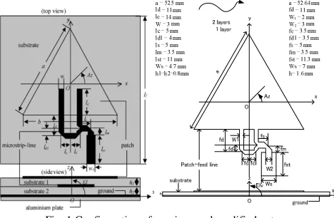
In microstrip antenna technology, it is necessary to make the manufacturing easy and to increase performances. In this case, the axial ratio (Ar) of the previous antenna configured in two layers that cause the capacitive coupling, the bandwidth difference, and various losses are embedded between the two layers. Therefore, it affect the current distribution on the patch surface decreasing the Ar performance.
Based on this idea, we can propose a new modified antenna as shown in Fig. 1. This figure shows the configuration of an equilateral triangle patch antenna with its parameters. There are two types of layer, two layers and one layer, using a conventional substrate (relative permittivity, εr = 2.17 and loss tangent, δ = 0.0009).
Fig. 1 Configuration of previous and modified antenna
B. Single Antenna Using Stub-fed
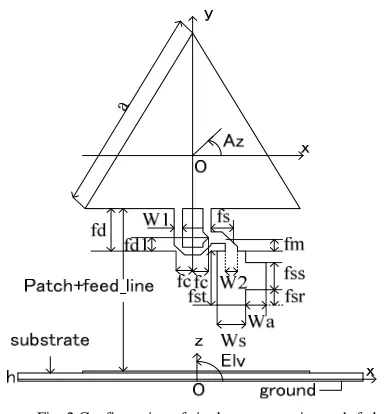
Fig. 2 shows the configuration of the equilateral triangle stub-fed antenna with use single layer. The various shapes of stub can be considered. The 3-models of stub that the stub position embedded on the right of microstrip-line as seen in Table I are investigated. Model-1 is the shape of antenna without use the stub. Model-2 and model-3 use the stub with Wa = 3 mm and Wa = 5 mm, respectively. However, all of them have similar characteristic performances, except the S-parameter and input impedance.
TABLE I ANTENNA PARAMETERS Parameter Value of
Model-1 (mm)
Value of Model-2 (mm)
Value of Model-3 (mm)
a 52.64 52.64 52.64
fd 11 11 11
fd1 3.5 3.5 3.5
fc 3.5 3.5 3.5
fs 5 5 5
fm 3.5 3.5 3.5
fsr - 4 3
fst 12 13.2 13
W1 2 2 2
W2 3 3 3
Wa - 3 5
Ws 7 7 7
The antenna is made of a thin conducting patch that the radiating patch and microstrip-line located on the same layer whose thickness is h = 1.6 mm and using a conventional substrate (εr = 2.17 and δ = 0.0009) [4], [11], [12].
Fig. 2 Configuration of single antenna using stub-fed
C. Array Antenna Using Stub-fed
Fig. 2 also illustrates the configuration of the single patch equilateral triangle antenna for array antenna. The antenna parameters are almost the same with the model-2, only difference in parameter fst and Wa about 14 mm and 5 mm for array, respectively. The configuration of array antenna is same with single antenna but the number of element patches are three which rotated 1200 each other, as shown in Fig. 3. There are three types of parameter size of single for array antenna, namely: without the use of stub with fst = 16 mm and Wa = 0 mm, the use of stub with fst = 14 mm and Wa = 3 mm, and the last ones is the use of stub with fst = 14 mm and Wa = 5 mm. In addition, the distance of the tip of the triangle to the central point, lo = 10 mm, the length of hexagonal ground g = 93.07 mm, and the angle between two adjacent patch seen from the central point, θ = 1200. The array antenna is also made from a conventional substrate (εr = 2.17 and δ = 0.0009) with the substrate thickness h = 1.6 mm. The element patch of this antenna is supplied by coplanar-fed where the width Ws = 7.0 mm for receiver antenna, Rx. Singly-fed forked can generate two waves with different phase 900 to obtain left hand circular polarization (LHCP). In the same manner, the circular polarization wave to the right (RHCP) can be realized by exchanging the microstrip-lines on the y-axis. The usage of feeding technique is to get the ideal and stable current distribution on the surface of the element patch antenna by increasing performance that developed previously [4], [7], [8], [12], [13].
Some types of triangle circular polarization antenna has been developed previously, but hard to be designed and optimized, since the ratio between the two sides of the
triangle (seen Fig. 1) affect the performance of axial ratio with a high level of sensitivity. Mechanical probe feeds are generally applied to produce circular polarization on a triangular patch antenna, but this technique is more difficult than coplanar-fed or microstrip-line in terms of the fabrication process [14], [15]. In addition, the feeding probe technique with a single-fed point will produce an unstable current distribution on each patch when the patches are composed of an array configuration. Therefore, coplanar-fed is used for an equilateral triangle patch antenna to design and fabricate the antenna easier without need to optimize the ratio between the two sides, as shown in Fig. 2 [16].
Fig. 3 Configuration of array antenna using stub-fed
III. RESULTS AND DISCUSSION
A. Single Antenna (Previous Antenna and Modified Antenna)
that, its disadvantages are difficult to fabricate, using length of feeding line and width-to-length ratio of radiating patch to control the match.
Fig. 4 Frequency characteristic of previous antenna
Fig. 5 Frequency characteristic of modified antenna
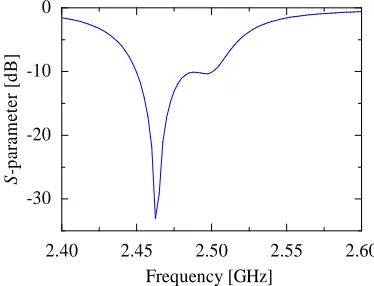
Fig. 6 shows the S-parameter of previous antenna has impedance bandwidth larger than modified antenna in Fig. 7. In this figure, the S-parameter decreases strongly at the resonant frequency caused by the loci of feeding antenna differences between two layers and one layer. Moreover, to increase the S-parameter of modified antenna in one layer, we change the width of antenna, Ws = 4.7 mm become 7 mm (seen Fig.1), but this way is just a little bit increasing of S-parameter. Hence, the next discussion is about optimized of modified antenna using stub-fed to increase the performance of antenna, especially S-parameter.
Fig. 6 S-parameter of previous antenna
Fig. 7 S-parameter of modified antenna
B. Single Antenna Using Stub-fed
Fig. 8 shows the frequency characteristic that not difference for all model, only a little bit shifting in the case of gain to up-down on the begin and end of the wave as function of frequency. It is similar type of the radiation pattern in Fig. 11 and Fig. 12.
Fig. 8 Frequency characteristic of single antenna using stub-fed
Otherwise, Fig. 9 depicts the strongly effects of stub. It is caused by the function of stub that decreasing the signal which absorbed by the antenna. Hence, the coefficient reflection become lower. In other word, the losses energy is less than without use the stub. This figure show that the sizes of stub affect toward S-parameter. In general, if the parameter of Wa or fss is set be higher, then the result of S-parameter is better than before. In this case, it is important to obtained the optimize results among S-parameter, input impedance, and the interesting shape of antenna. If the size of stub is similar or bigger than the microstrip-line, it is not good for designing the antenna.
Fig. 10 describes about the characteristic of input impedance. It seem that the fixed real impedance occur at 50 Ω, while the tip of signals at the resonant frequency tend to decreases, seen from the increasing of the stub sizes. So, the stub antenna has to set about Wa = 5 mm and fss = 7 mm. In this case, the real and reactance impedance at f = 2.5025 GHz occur about 47.92 Ω and 0.96 Ω, respectively.
2.40 2.45 2.50 2.55 2.60 0 2 4 6 8 0 1 2 3 4 5 Frequency [GHz] G ai n [ d B ic ] A x ia l ra ti o [ d B ] Gain Axial ratio
2.4 2.45 2.5 2.55 2.6
0 2 4 6 8 0 1 2 3 4 5 70 [MHz] 13.46[MHz]
[2.5025 , 0.27] [2.5025 , 6.62]
G ai n [ d B ic ] A x ia l ra ti o [ d B ] Frequency [GHz] Gain Axial ratio
2.40 2.45 2.50 2.55 2.60
-30 -20 -10 0 Frequency [GHz] S -p ar am et er [ d B ]
2.4
2.45
2.5
2.55
2.6
-30
-20
-10
0
2.5087 [GHz]
2.4875 [GHz] 21.2 [MHz]
Frequency [GHz]
S
-p
ar
am
et
er
[
d
B
]
2.4 2.45 2.5 2.55 2.6
Fig. 9 S-parameter of single antenna usingstub-fed
Fig. 10 Input impedance of single antenna using stub-fed
TABLE II
PERFORMANCES OF THE STUB ANTENNA at f = 2.5025 GHz
Model S-parameter (dB) Real-Z (Ω) Imaginer-Z (Ω)
1-stub-00 -10.99 50.05 24.72
2-stub-73 -15.48 50.07 12.04
3-stub-75 -21.49 47.92 0.96
Fig. 11 and Fig. 12 depict the relationship between gain
and elevation angle at azimuth, Az = 00 and 900. At the
elevation 900 the maximum gain and the minimum axial
ratio are about 6.62 dBic and 0.27 dB in both of azimuth angle, respectively. The effect of using stub in case of the elevation plane is little different than without stub.
Fig. 11 The elevation of x-z plane of single antenna using stub-fed
Fig. 12 The elevation of y-z plane of single antenna usingstub-fed
C. Array Antenna Using Stub-fed
Fig. 13 to Fig. 15 show the simulation results of antenna
array, such as frequency characteristics, S-parameter, and
impedance input. While Fig. 16 and Fig. 17 are specific to the performance of the antenna array, namely the vertical and the horizontal radiation patterns.
Fig. 13 shows the value of the gain and axial ratio (Ar)
for the three types of simulation well-fed antenna without
stub-fed and with stub-fed in different sizes at the frequency
target 2.5025 GHz. The value of each gain almost same, around 6.93 dBic and also this case occur for each axial
ratio, roughly 2.43 dB. In addition, the gain-bandwidth
-5dBic of the three types of antenna is also almost same,
around 2.59%. While the axial ratio-bandwidth-3dB for the
three types of antenna is approximately 0.7%.
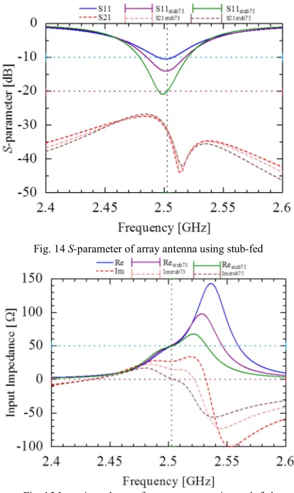
Fig. 14 shows the relationship between the S-parameters
and frequencies for simulation of receiver antenna (Rx). In
this figure, it can be seen that the S-parameter (S11) of the
three types of antenna (without stub-fed, stub-fed73 and
stub-fed75) at the frequency target 2.5025 GHz about -11 dB,
-15 dB, and -20 dB, respectively. Then, the S-parameters
(S22) of the three types of antenna are almost same, roughly
-33 dB.
Fig. 13 Frequency characteristic of array antenna using stub-fed
Fig. 15 illustrates the characteristics of the input
impedance of Rx. This figure shows that the real parts of the
simulation have similar results at the frequency target 2.5025 GHz that is equal to 50 Ω. However, if there is any different model probably this is beyond the frequency target.
2.4 2.45 2.5 2.55 2.6
-200 -150 -100 -50 0 50 100 150 200 250 In p u t im p ed an ce [ Ω ] Frequency [GHz] Re Im Re-73 Im-73 Re-75 Im-75
2.4 2.45 2.5 2.55 2.6
-30 -20 -10 0 S -p ar am et er [ d B ] Frequency [GHz] S-parameter S-parameter-73 S-parameter-75 0 2 4 6 8 0 2 4 6 8 90
60 60 30
30
0 0
El-Elevation angle [deg]
G a in [ d B ic ] A x ia l ra ti o [ d B ] Gain Axial ratio Az=0o Az=180o Gain-73 Axial ratio-73 Gain-75 Axial ratio-75 0 2 4 6 8 0 2 4 6 8 90 60 60 30 30 0 0
El-Elevation angle [deg]
But the reactance parts of the simulation are vary depend on the frequency target, that are consecutively of the antenna
without a stub-fed, stub-fed73 and stub-fed75, i.e. 30 Ω, 15 Ω
and 0 Ω. Furthermore, the impedance bandwidth (below -10
dB) of the three types of antenna (without stub-fed, stub
-fed73 and stub-fed75) are about 20 MHz, 35 MHz and 60
MHz, respectively.
Fig. 14 S-parameter of array antenna using stub-fed
Fig. 15 Input impedance of array antenna using stub-fed
Fig. 16 shows the relationship between the characteristics
of the radiation (gain-axial ratio) in the part of Az = 00 and
elevation angle when the one of three patches antenna is switched OFF and the others switched ON. The results indicate that from the northern tip to the southern tip of
Japan elevation angle of 380 to 580 relative to the satellite
position (above the equator) for the three types of antenna mentioned above, yield the desired target (as shown in Fig. 16).
Fig. 16 Elevation cut plane of array antenna using stub-fed
Fig. 17 describes the characteristic of conical pieces
radiation in the El = 48° area. In this figure is seen that the
peak of the gain and axial ratio for the three types of antenna are almost same, around 7.56 dBic and 0.13 dB, respectively. In addition, the values of the gain and axial
ratio beamwidth meet the target for beam coverage of 1200.
Fig. 17 Conical cut plane of array antenna using stub-fed
IV. CONCLUSIONS
The analysis of previous antenna (two layers) and modified antenna (one layer), optimized modified antenna
using stub on coplanar-fed both single and array antenna
have been discussed. The result for axial ratio of the modified antenna and the previous antenna at 2.5025 GHz are 0.27 dB and 1.02 dB, respectively. It is caused a
coplanar-fed which connected directly to the radiating patch
(one layer antenna). The use of stub can increase S
-parameter, about more than -10 dB. The results of single
antenna, especially for bandwidth of axial ratio below 3-dB
and gain above 5 dBic are about 0.02 GHz and 0.065 GHz,
respectively. Furthermore, the results of 5-dBic-gain and the
3-dB-axial ratio beamwidth are consecutively about 600 and
1200, respectively. The results of array antenna, in the case
of bandwidth of axial ratio below 3-dB and gain above 5
dBic are about 0.03 GHz and 0.3 GHz, respectively.
Moreover, the results of 5 dBic-gain and the 3 dB axial ratio
beamwidth for elevation cut plane are about 480 and 870,
respectively. Moreover, gain over 5 dBic and axial ratio less than 3 dB can be obtained according to the desired target,
the beam coverage area of them are 1200 and elevation
angle of them are from 380 to 580.
ACKNOWLEDGMENT
Finally, special thanks to Ministry of Finance, Indonesia Endowment Fund for Education (LPDP) and Ministry of Research, Technology and Higher Education for the support of scholarship.
REFERENCES
[1] Pozar and David M., “A Review of Bandwidth Enhancement Techniques for Microstrip Antennas,” in Microstrip Antennas The Analysis and Design of Microstrip Antennas and Arrays, New York : IEEE Press, pp.157-166, 1995.
[2] C.K Aanandan, P. Mohanan, and K.G. Nair, “Broadband Gap Coupled Microstrip Antenna,” IEEE Transaction on Antennas and propagation, Vol.3. No.10, 1990.
[3] M. F. E. Purnomo, E. Supriana, and V. Kusumasari, “Circularly polarized array pentagonal microstrip antenna for mobile satellite applications,” IEEE Xplore Conference Publications QiR (Quality in Research), 25-28 June 2013, Feb. 7, 2014.
[4] J.T. Sri Sumantyo, K. Ito, and M. Takahashi, “Dual-Band Circularly Polarized Equilateral Triangular-Patch Array Antenna for Mobile Satellite Communications, “IEEE Transactions on Antennas and Propagation, vol.53 No.11, Nov. 2005.
[5] M.F.E. Purnomo, S.H. Pramono, M. A. Pamungkas, and Taufik, “Study of The Effect of Air-Gap on Array Microstrip Antenna Performances for Mobile Satellite Communications,” ARPN Journal of Engineering and Applied Sciences, ISSN 1819-6608, Vol.10.No.20, 2015.
[6] Ansoft Corporation, ANSOFT Ensemble user guide manual (ver. 8), 2001.
[7] J. T. S. Sumantyo and K. Ito., “Simple satellite-tracking triangular-patch array antenna for ETS-III applications,” IEICE Tech.Rep., AP2003–236, 2004.
[8] J. T. S. Sumantyo, K. Ito, D. Delaune, T. Tanaka, and H.Yoshimura, “Simple satellite-tracking dual-band triangular patch array antenna for ETS-VIII applications,” Proc. IEEE Int Symp. Antennas and Propagation, pp. 2500–2503, 2004.
[9] Basari, “Development of Simple Switched-Beam Array Antenna System for Mobile Satellite Communications,” Master Graduation Thesis, Feb. 2008.
[10] M. F. E. Purnomo, Basari, and J. T. S. Sumantyo, Circularly Polarized Stack-Patch Microstrip Array Antenna for Mobile Satellite Communications,” Proceedings IJJSS 2014.Theme Antenna and Microwave: 269-275, 2014.
[11] J.H. Jang, M. Tanaka, and N. Hamamoto, “Portable and deployable antenna for ETS-VIII,” Interim International Symposium on antenna and Propagation, pp. 49-52, 2002.
[12] J. T. Sri Sumantyo and K. Ito,”Low profile satellite-tracking dual-band triangular-patch array antenna for mobile satellite communications,”Technical Report of IEICE, AP2004-133, pp.19-24, Tokyo, October, 2004.
[13] H. Ishihara, A. Yamamoto, and K. Ogawa, “A simple model for calculating the radiation patterns of antennas mounted on a vehicle roof,” Interim International Symposium on Antenna and Propagation, pp. 548-551, 2002.
[14] M. F. E. Purnomo and S.N. Sari, “Singly-fed Circularly Polarized Triangular Microstrip Antenna with Truncated Tip Using Annular Sector Slot for Mobile Satellite Communications,” Proceedings EECCIS 2012. 172-EEC-35, 2012.
[15] M. F. E. Purnomo, H. Suyono, P. Mudjirahardjo, R. N. Hasanah, “Analysis Performance of Singly-Fed Circularly Polarized Microstrip Antenna For Wireless Communication,” Jurnal Teknologi, e-ISSN 2180-3722, Vol. 78. No. 5-9, 2016.