“
Mathematical Validation of Optimized
Design of EGR Cooler of CRDI Diesel Engine
for NOx Emission Control using CFD
Analysis‖
Rambhajan Prajapati#1, Vishal Achwal#2, Dr. Suman Sharma #3 #1
Research scholar, Department of Mechanical Engineering, SIRT, Indore
#2
Assistant Professor, Department of Mechanical Engineering, SIRT, Indore.
#3
Professor & Head of Department of Mechanical Engineering, SIRT, Indore. SIRT, Indore, Madhya Pradesh, India
Abstract
Euro 6 is a significant advancement with regard to NOx limits. The NOx limit declines from
0.18 g/ km to 0.08 g/km, a reduction of 56% as compared to Euro 5 norms. This has significant implications for control technologies, requiring for the first time the integration of emission control aftertreatment for NOX emissions like improvising exhaust gas recirculation (EGR) coolers. Exhaust Gas Recirculation coolers (EGR) have to withstand high thermal stresses due to large temperature gradients between the hot exhaust gas and the coolant. Two different designs of EGR coolers are analyzed using CFD technique to determine effectiveness. The design of EGR cooler is shell and tube type having single entry for coolant in first design and multiple entry for coolant in second design in which the coolant passes through the shell to cool down the exhaust gas inside tubes. The thermo-flow characteristics inside the EGR Cooler and surface temperature have been investigated also by using CFD code ANSYS CFX 14.0. Standard k-epsilon turbulence model is used for analysis.
Keywords —EGR Cooler, NOx, CFD
I. INTRODUCTION
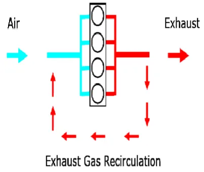
Engine emissions are toxic gases that cause health problems to humans and damage the environment. To decrease these emissions, a number of laws have been implemented throughout the world, limiting the amount of these emissions that a vehicle may emit. It is possible to reduce the formation of emissions during the combustion to comply with exhaust emission legislation. The raw emissions are reduced and thus no or less aftertreatment is needed. A portion of the exhaust gases is recirculated into the combustion chambers. This can be achieved either internally with the proper valve timing, or externally with some kind of piping, Figure 9 shows this schematically. In a spark-ignited engine running, the recirculated exhaust gases are virtually inert as they contain almost no oxygen. In a diesel engine, the
exhaust gases always contain oxygen but their oxygen concentration is lower than that of fresh air. They have instead a larger concentration of the inert three-atomic gases carbon dioxide and water vapor. By mixing the exhaust gases with the intake air, the oxygen concentration of the cylinder charge is lowered. This leads to a reduction of the combustion temperature by different effects. As the air is diluted with exhaust gas, the mass of a gas portion containing the needed amount of oxygen gets bigger. The fuel molecules need to mix with a larger volume of gas to find the oxygen molecules they need to react.
Figure 1: Exhaust Gas recirculation
The energy of the same fuel amount is thus used to heat up a larger gas portion than it would without EGR, resulting in a lower temperature. Another effect is the change in heat capacity.
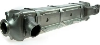
Figure 2: EGR cooler
The exhaust gas drawn off for recirculation has a temperature of around 650 degrees Celsius. It is therefore far too hot to be fed directly into the cylinders; it would increase the temperature of the combustion chamber even further, thereby defeating its actual purpose — that of reducing nitrogen oxide formation by lowering the combustion temperature. For this reason, the exhaust gas is first cooled to around 120 degrees Celsius.
II. LITERATURE REVIEW
Simon Reifarthit [1] It gives an overview of the field of EGR and diesel combustion and presenting the methods used in this work. This work provides a simulative comparison of different EGR systems, such as long-route EGR, short-route EGR, hybrid EGR, a system with a reed valve and a system with an EGR pump. Both the steadystate performance and transient performance are compared.
Jaffar Hussain et al [2] studied the effect of EGR on performance and emissions in three cylinders, air cooled and constant speed direct injection diesel engine, which is usually used in agricultural farm machinery. Such engines are normally not operated with EGR. The experiments were performed to experimentally evaluate the performance and emissions for different EGR rates of the engine. B. Jothithirumal et al [3] conducted experiment on the effect of exhaust gas recirculation on the exhaust gas temperature. The experimental set up for proposed experiments was developed on two-cylinder direct injection air cooled compression ignition engine experiment was conducted for observing the effect of different quantities of EGR on exhaust gas temperature.
Deepak Agarwal et al [4] conducted a test on a single cylinder DI diesel engine and calculated the performance and emission characteristics with rice bran methyl ester (RBME) and its blends as fuel with EGR system. They optimized and reported that 20% biodiesel blends with 15% EGR produce less NOx, CO and HC emissions and also enhanced thermal efficiency and reduced BSFC.
B. Deet al [5] In this paper an experimental study is carried out on an I.C. engine laboratory single
cylinder, four-stroke VCR, direct injection diesel engine to analyze the performance and emission characteristics of pure diesel, Jatropha oil and Jatropha oil-diesel blended fuels with different blended rates. The measurements are recorded for the compression ratio of 16, 17 and 18 varying the load from idle to rated load of 3.7 kW. Comparative results are given at constant engine speed, variable compression ratio and various engine loads for pure diesel, Jatropha oil and Jatropha oil-diesel blended fuels revealing the effect of diesel, Jatropha oil and Jatropha- diesel blended fuels combustion on engine performance and exhaust emissions.
Zhang et al. [6] investigated the effect of diesel soot deposition on the performance of a small 6-tube shell and tube heat exchanger by operating the engine at medium load which produced an exhaust gas temperature of around 250 °C. They found that fouling increased the thermal resistance and pressure drop by 150% during 12 hours of exposure. The rate of increase of the thermal resistance decreased over this period and approached an asymptotic value.
III. PROPOSED WORK
The overall objective of this research is to improve effectiveness of EGR by varying shell design using techniques of Computational Fluid Dynamics to achieve better heat transfer rate and effectiveness. The software used for analysis is ANSYS CFX and CAD modeling is done using Creo 2.0. The base design for analysis is taken of CRDI engine.
IV. METHODOLOGY
to display the geometry/mesh, create vector, contour, and 2D and 3D surface plots. Particles can be tracked throughout a simulation, and the model can be manipulated (i.e. changed by scaling, rotating, etc.), and all in full coloured animated graphics.
Table 1:Design specification for EGR
Parameters
EGR 1
No. of tubes
28
No. of baffles
3
Tube length
180
Total length
230
Inlet coolant side
diameter
19.5
Outlet coolant side
diameter
19.5
Inlet exhaust side
diameter
30
Outlet exhaust side
diameter
30
Figure 3: EGR cooler of single entry
Figure 4: Computational domain of single entry EGR
Table 2: Engine specification for CRDI engine
Parameters
DescriptionType Inline Five cylinder, 4 stroke, CRDI engine Power 90 KW @2950 rpm
Peak torque 320Nm@1400-2400 rpm
Bore X Stroke 90.5X 90.9 Compression ratio 16.5:1
V. DATA REDUCTION
The parameters which were of key interest were outlet temperature, outlet pressure, velocity outlet. Design of heat exchanger is done by LMTD method and tubular exchangers manufacturers association standard. Also permissible amount of pressure drop is measured by related equation
In the LMTD method heat transfer is calculated by following method
𝐴 =𝑄 / 𝑈𝑜∗∆𝑇𝑚
Logarithmic temperature difference can be calculated as :
ΔT2=Th1-Tc2 ΔT2=Th2-Tc1
∆𝑇𝑚 =∆𝑇1−∆𝑇2 /ln ( ∆𝑇1 ∆𝑇2)
Overall heat transfer coefficient can be calculated as:
Bell Delware method is used to calculate heat transfer coefficient. Shell side heat transfer coefficient can be calculated as:
ho = ji* Cp* (ms/As) *( K/Cp*μs)^(2/3) * (μ/μs*w)^0.14
Tube side heat transfer coefficient can be calculated as:
The CAD model of EGR cooler is modeled using Creo 2 software which is sketch based, feature based parametric 3d modeling software developed by PTC .
The meshing for is carried out using ANSYS mesher. Here element shape is taken as brick and fine sizing with relevance 100. Other meshing parameters such as smoothing is set to medium , transition slow, curvatue angle 120
Figure 6: Meshed model of single entry EGR cooler
The upwind scheme ―second order upwind scheme‖ was selected for momentum and energy equations. In order to couple velocity and pressure, the SIMPLE algorithm was applied. Temporal discretization was achieved using the solution method ―Implicit integration‖. Standard scheme was utilized to interpolate pressure and the relaxation factors for pressure, density, body forces, momentum and energy were maintained at 0.3, 1, 1, 0.7 and 1 respectively. A low convergence criterion of 10 -4 was chosen for energy equation and 10-3 was chosen for continuity and velocity equation for the residuals in order to accurately predict different parameters. The solution was initialized by computing from the inlet using ―Standard Initialization‖ option. After the completion of these settings, the iteration procedure was initiated by clicking on ‗Run Calculation‖ button.
VI. RESULTS AND DISCUSSION
The CFD analysis conducted on EGR cooler with single entry and multiple entry is simulated and contour plot of temperature, pressure and velocity are plotted as shown in section below. As engine works at different RPM thereby resulting in different emission gas temperatures. To analyze the cooling of EGR cooler different operating temperatures has been taken viz 419 0C ,589 0C,688 0C, 786.20C.
Figure 7: Velocity plot for 1st design EGR cooler
The velocity contour along with mid-section plane is shown in fig 7 above. The velocity of EGR
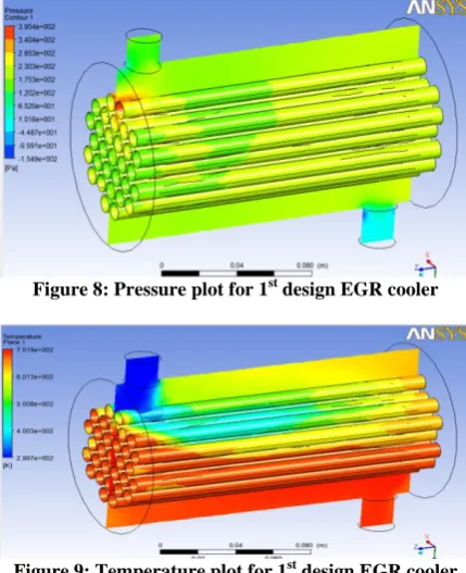
coolant is highest at inlet section of EGR cooler which reduces considerably as we move towards shell side of EGR cooler and increases towards exit shown by yellow colour. Velocity increases and then decreases as we move across the shell. The pressure contour along with mid-section plane is shown in fig 8. The pressure value of EGR is highest at inlet section of EGR cooler which reduces considerably as we move towards shell side of EGR cooler and increases towards exit shown by blue colour. The pressure value remains almost constant towards middle right zone of shell.
Figure 8: Pressure plot for 1st design EGR cooler
Figure 9: Temperature plot for 1st design EGR cooler
The temperature contour along with mid-section plane is shown in fig 9 above. The portion of tubes containing EGR gas which is in immediate contact with coolant shown by dark blue colour and light blue colour has the lowest temperature while the portion of pipe away from coolant inlet shows higher temperature shown by dark red colour. Subsequent CFD analysis is conducted on 2nd design EGR cooler with multiple inlet entries and contours are plotted. At low proportions of entrance diameter to shell diameter (D1/D2), flow percent decreases at side tubes
Figure 10: Velocity plot for 2nd design EGR cooler
The velocity contour along with mid-section plane is shown in fig 10. The velocity of EGR coolant is highest at inlet 1st and 4th section of EGR cooler shown by green color contour which reduces considerably as we move towards shell side of EGR cooler and increases towards exit shown by yellow color. Velocity increases and then decreases as we move across the shell.
Figure 11: Pressure plot for 2nd design EGR cooler
The pressure contour along with mid-section plane is shown in fig 11. The pressure value of EGR is highest at inlet section of EGR cooler shown by red and yellow color contour which reduces considerably as we move towards shell side of EGR cooler and increases towards exit shown by blue colour. The pressure value remains almost constant towards middle zone of shell. Shown by green color.
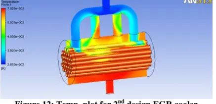
Figure 12: Temp. plot for 2nd design EGR cooler
The temperature contour along with mid-section plane is shown in fig 12 above. The portion of tubes containing EGR gas which is in immediate contact with coolant shown by dark blue colour and light blue colour has the lowest temperature while the portion of pipe away from coolant inlet shows higher temperature shown by dark red color
.
Table 3: Temp table for single entry EGR cooler gas
GAS IN
TEMP(K) 692.92 862.85 961.0 1059.2
GAS OUT
TEMP(K) 357 482.85 551.0 689.26
COOLANT
IN TEMP(K) 341 341 341 341
COOLANT OUT
TEMP(K) 349.26 352.58 353.4 350.65
Output data of EGR cooler with multiple entry coolant temperature at inlet and outlet, gas temperature at inlet and outlet is provided in table 4
Table 4: Temperature table for single entry EGR cooler coolant
OPERATING
TEMP(K) 692.92 862.85 961.05 1059.26
GAS IN
PRESSURE(Pa) 129938 129938 129938 129938
GAS OUT
PRESSURE(Pa) 129445 129445 129445 129445
COOLANT IN
PRESSURE(Pa) 105645 105645 105645 105645
COOLANT OUT
PRESSURE(Pa) 105390 105390 105390 105390
Figure 14: Coolant inlet and outlet temperature graph of single entry EGR cooler
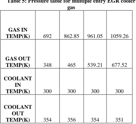
Table 5: Pressure table for multiple entry EGR cooler gas
GAS IN
TEMP(K) 692 862.85 961.05 1059.26
GAS OUT
TEMP(K) 348 465 539.21 677.52
COOLANT IN
TEMP(K) 300 300 300 300
COOLANT OUT
TEMP(K) 354 356 354 351
Subsequent analysis has been carried on 2nd design having multiple inlet entry for coolant using ANSYS CFX under the same boundary conditions. The results are discussed in next section
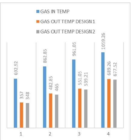
Figure 15: Gas inlet and outlet temperature graph for of multiple entry EGR cooler
Figure 16: Coolant inlet and outlet temperature graph for of multiple entry EGR cooler
Figure 17: Coolant inlet and outlet temperature graph for of multiple entry EGR cooler
VI. CONCLUSION
The EGR (exhaust gas recirculation) technique can greatly reduce the NOX emission of diesel
engines, especially when an EGR cooler is employed. Numerical simulations are applied to study the flow field and temperature distributions inside the EGR cooler. Two designs of EGR cooler are analyzed using ANSYS CFX under same operating conditions. First design is based on single entry of coolant while second design is based on multiple entry of coolant in EGR cooler. It has been found that 2nd design of EGR cooler with multiple inlet for coolant performs better in terms of cooling effectiveness as compared to 1st design with single inlet for all operating temperatures. This can be attributed to better heat transfer achieved in 2nd design due to more turbulence and turbulent flow heat transfer.
ACKNOWLEDGMENT
The completion of this project has required the help and support of numerous people. Specially, I would like to extend sincere gratitude to my guide Mr. Vishal
Achwal, Professor and Dr. Suman Sharma, HOD
Department of Mechanical Engineering, Sage University, Indore for all of his help and guidance throughout this research. They inspire and encourage me to work on this research. I also appreciate not only for his professional, timely and valuable advices, but also for his continuous scheduled follow up and valuable comments during my research. My special gratefulness goes to my family for their support, encouragement, patience and understanding. I feel a deep sense of appreciation for my father and mother who formed my vision, and taught me the good morals, starting from childhood to now, that truly matter in life.
REFERENCES
[1] Simon Reifarth, EGR-Systems for Diesel Engines, Licentiate thesis KTH CICERO, TRITA – MMK 2010:01, ISSN 1400-1179, ISRN/KTH/MMK/R-10/01SE.
[2] Jaffar Hussain, K. Palaniradja, N. Alagumurthi, R. Manimaran, Effect of Exhaust Gas Recirculation (EGR) on Performance and Emission characteristics of a Three Cylinder Direct Injection Compression Ignition Engine, Alexandria Engineering Journal ,2012, (51), pp. 241– 247.
[3] B.Jothithirumal and E. James gunasekaran, Combined Impact of Biodiesel and Exhaust Gas Recirculation (EGR) on NOX Emission in Diesel Engine, ELSEVIER, Procedia Engineering, 2012, (38), pp.1457-1466.
[4] Deepak Agarwal, Shailendra Sinha, Avinash Kumar Agarwal, Experimental investigation of control of NOX emissions in biodiesel- fueled compression ignition engine, ELSEVIER, Renewable Energy, 2006,(31) pp. 2356–2369.
[5] B.De and R. S. Panua, An experimental study on performance and emission characteristics of vegetable oil blends with diesel in a direct injection variable compression ignition engine, ELSEVIER, Procedia Engineering, 2014, (90), pp. 431 – 438.