International Journal of Emerging Technology and Advanced Engineering
Website: www.ijetae.com (ISSN 2250-2459, ISO 9001:2008 Certified Journal, Volume 5, Issue 1, January 2015)
246
Fuzzy Based Grid Synchronization Method for Distributed
Energy Resource Converters
K. Venkata Sudheer Kumar
1, U. Chandra Rao
2, Ch. Rambabu
31P.G.Scholar, 2Associate Professor, 3Professor & Head, Dept of EEE, Sri Vasavi Engineering College, W.G. District,
A.P, India
Abstract—Now a days, renewable energy resources such as
solar Photo Voltaic (PV) cells, fuel cells (FC) and wind turbines(WT) plays an important role in generating electricity nearer to local loads that are integrated to utility grid. For integration of distributed energy resource converters to utility grid, a synchronization i.e matching of frequency, phase, amplitude of output voltages, active power and reactive power must exist in between output of distributed energy resource converters and utility grid. The main objective of this paper is to maintain synchronism between the output of distributed energy resource converter with utility grid. In this paper a fuzzy based grid synchronization method is proposed to achieve the synchronization. The proposed method is modeled and simulated in MATLAB/SIMULINK Software.
Keywords—Distributed Generation Systems (DGSs), Grid
Synchronization, Microgrid, Fuzzy Logic Controller.
I. INTRODUCTION
Nowadays, renewable energy sources (RES) or Distributed Energy Resources (DERs) plays an important role for generating electricity in world-wide economy. Distributed Generation (DG) also known as small-scale (typically 1KW-50 MW) electric power generators used to produce electricity nearer to the location of customers that are tied to a microgrid. Renewable energy resources such as solar photo voltaic, wind turbines and fuel cells are used for distributed generation. Distributed generation enhances the reliability of power supply. The capital cost of distributed generation system is usually low based on its size as explained in [1].
A microgrid is a part of distribution network that includes multiple loads and distributed energy resource converters that are operated in parallel with the boarder utility grid [2]-[5]. It helps in integration of distributed energy resource converters to microgrid. Microgrid is a part of distributed generation system. It is a localized grouping of electricity generation, energy storage and loads that normally operates connected to a traditional centralized utility grid. The components of microgrid involves distributed generation resources such as photovoltaic panels, small wind turbines, fuel cells, etc.
The storage devices are batteries, super capacitors, flywheel etc along with local loads. Better efficiency, superior quality with high reliability of power supply having environmental as well as economical benefits can be achieved by using microgrid. A droop control is a control technique applied to distributed generation system for primary frequency control and as well as voltage control for load sharing between local loads to utility Grid.
By controlling the frequency, as well as voltage, corresponding active power (P) and reactive power (Q) can be controlled in distributed generation. Increase in active power output results in reduction of frequency and the corresponding increase in the reactive power results in decrease of voltage as explained in [6].
The concept of Phase Locked Loop (PLL) is used for the implementation of grid synchronization method. PLL is used for the estimation of grid voltage, phase angle and frequency. A PLL is a control system in which output signal is generated by relating its phase to the phase of an input signal. A PLL can track an input frequency or it can generate a frequency that is a multiple of the input frequency as explained in [7]-[10].
This paper a fuzzy logic controller based
synchronization method is proposed for achieving the grid synchronization in terms of frequency, phase angle, amplitude of output voltages, active power and reactive power in between converter output and Distributed Energy Resource Converters (DERCs). The fuzzy logic controller is replaced by proportional integral (PI) controller for obtaining fast dynamic response, low steady error and for stable operation of the grid as explained in [18]-[19].
II.OPERATION OF DISTRIBUTED ENERGY RESOURCE
CONVERTERS
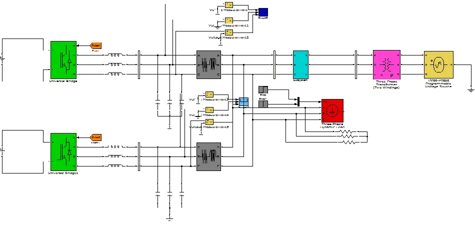
Fig.1 represents the proposed distributed generation system comprises of two Voltage Source Inverters (VSI) fed with a source with line impedances R1+ jX1 , R2 + jX2
International Journal of Emerging Technology and Advanced Engineering
Website: www.ijetae.com (ISSN 2250-2459, ISO 9001:2008 Certified Journal, Volume 5, Issue 1, January 2015)
[image:2.612.77.530.128.329.2]247
Fig.1: Proposed DG system with Utility Grid
The static switch is open before synchronization that is in islanded mode of operation. By closing the static switch the distributed generation system is connected to utility grid based on the commands received from the secondary controller after the synchronization achieved in terms of frequency, phase, and amplitude of output voltages, active power and reactive power [16]-[17]. The distributed generation system structure is operated in two modes. They are Grid Connected (GC) mode and Islanded or Stand Alone (SA) mode. In Grid connected mode of operation, the utility grid is active and static switch is closed thereby distributed generation system is connected to utility grid after the grid synchronization is achieved. In Islanded mode of operation utility grid is inactive and it does not supplies power and static switch is open.
III. CONTROL OF DISTRIBUTED ENERGY RESOURCE
CONVERTERS
The controllers [8] involved in distributed generation system structure are:
a) Primary controller or PLL controller:
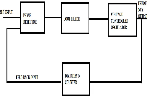
The primary controller senses the difference voltage from the utility grid voltage and point of common coupling voltage. A phase locked loop block is used in the primary controller to generate the input frequency signals from the primary controller. A phase locked loop is a control loop which generates an output signal by comparing its phase to the phase of an input signal. By maintaining the input and output frequencies lock step also implies keeping the input and output frequencies the same. It can also senses a frequency, in addition of synchronizing the
signals
[7].Fig.2. represents the block diagram of Phase Locked Loop (PLL).
Fig 2: Block Diagram of PLL Controller
A phase detector relates the reference input to the feedback input and generates an error signal. The error signal is then passed through a loop filter for harmonic elimination which is fed to the voltage controlled oscillator that helps in generating a periodic frequency output from the given input reference signal.
[image:2.612.327.576.375.547.2]International Journal of Emerging Technology and Advanced Engineering
Website: www.ijetae.com (ISSN 2250-2459, ISO 9001:2008 Certified Journal, Volume 5, Issue 1, January 2015)
248
Parks transformations are involved in conversion of voltages from three phase to two phase ( abc – dq ).
The mathematical modeling that involves in primary controller for generating the difference voltage and phase angle difference is:
PCC G
d
V
V
V
(1)
Where,
dV
Difference voltage
G
V
Grid voltage
PCC
V
Point of common couplingVoltage
d
G
PCC (2)Where,
D
Phase angle difference
G
Phase angle of grid
PCC
Point of Common Coupling phase angleb) Secondary controller:
The secondary controller is linked to the primary controller from where the operation mode signals such as phase angle difference
d,
V
d differential voltage is taken from the primary controller. The secondary controller involves the sharing of active power as well as reactive power explained in [12]. The mathematical modeling involved in the secondary controller is [13]-[15].Instantaneous active power,
q q d
d
i
u
i
u
p
(3)Where,
p= Instanteneous active power
q
d
u
u
,
Instanteneous voltages along d and q axes
q
d
i
i
,
Instanteneous currents along d and q axesand
Instantaneous reactive power ,
q q d
d
i
u
i
u
q
( 4)
Where,
q
Instanteneous reactive power
q
d
u
u
,
Instanteneous voltages along d and q axes
q
d
i
i
,
Instanteneous currents along d and q axesThe relationship between active power (P) and frequency (f) is expressed as:
)
(
00
k
p
p
f
f
p
(5)Where,
f
=System frequency
0
f
Base frequency
p
k
Frequency droop control setting p=Active power of the unit
0
p
base active power of the unitSimilarly, the relationship between reactive power (Q) and frequency (f) is expressed as
)
(
00
k
Q
Q
V
V
q
( 6)Where,
V=voltage of the measurement location
q
k
voltage droop control setting
0V
base voltageQ= Reactive power of the unit
0Q
Base reactive power of the unit.International Journal of Emerging Technology and Advanced Engineering
Website: www.ijetae.com (ISSN 2250-2459, ISO 9001:2008 Certified Journal, Volume 5, Issue 1, January 2015)
249
IV. FUZZY LOGIC CONTROLLER
[image:4.612.50.285.219.340.2]The concept on fuzzy set theory was introduced by L. A. Zadeh in 1965. Fuzzy Logic is rule based and it is application of human knowledge on system behavior as explained in [18]-[19]. Fig.3 represents the schematic diagram of fuzzy based system.
Fig 3: Schematic of Fuzzy based system
Fuzzy logic controller operation mainly involves the execution of four major operations:
Fuzzification
Rule based Inference system
Composition and Defuzzification
Fuzzification involves the conversion of crisp values or classical set values to Fuzzy rule base values. It involves the choice of Variables, fuzzy Input and output variables and the evaluation of membership functions. It involves fuzzy subset rules, composition and defuzzification. For assigning each fuzzy subset rule based value to the output variable a Rule based fuzzy inference system is necessary. Composition helps in forming a Single fuzzy subset rule based Value assigned to an output variable from a multiple rule based fuzzy subset values.
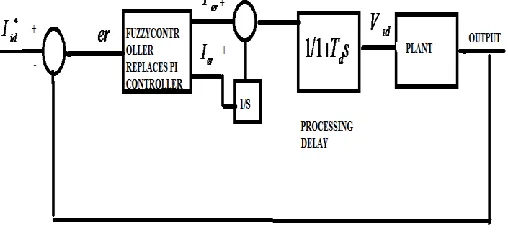
[image:4.612.320.578.232.708.2]Defuzzification helps in the conversion of composition of fuzzy rule based value to a single crisp value. A PI controller is replaced with a fuzzy controller is as shown in fig.4.
Fig 4: Block diagram of fuzzy controller
The fuzzy logic controller helps in attaining the quick, stable response and in reducing the steady state error. The
instanteneous current
I
id is compared with the reference currentI
id to generate the error signal which is fed to the fuzzy logic controller. The fuzzy logic generates the corresponding output based on the corresponding rule based system and membership functions.(a) Error (e)
(b) Change of Error (de)
[image:4.612.48.302.585.701.2]International Journal of Emerging Technology and Advanced Engineering
Website: www.ijetae.com (ISSN 2250-2459, ISO 9001:2008 Certified Journal, Volume 5, Issue 1, January 2015)
250
A.Fuzzy logic rules:
[image:5.612.332.546.217.299.2] [image:5.612.43.310.263.623.2]The main objective of designing the Fuzzy logic rules is to synchronize the grid parameters such as grid frequency, phase angle, amplitude of output voltages, active power and reactive power with the output of the distributed energy resource converters. The error and change of error are the inputs of the fuzzy logic controller. The corresponding error and change of error are divided into seven groups. The rules of fuzzy logic controller are shown in below Table 1.
Table 1: Fuzzy Logic Rule Table
Where, NH:Negative High NM:Negative Medium NS:Negative Small ZE:Zero PH:Positive High PM:Positive Medium PS: Positive Small
V. SIMULATION RESULTS
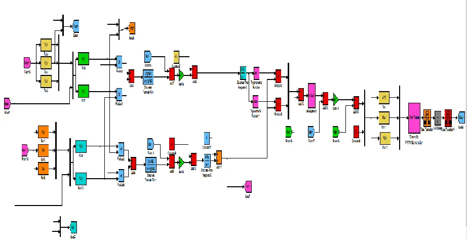
Fig.6 represents the simulink model of the proposed DG System with utility grid.
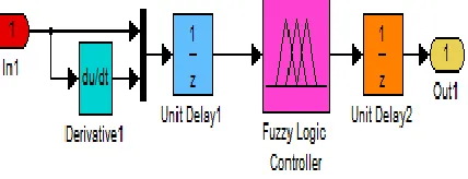
The fuzzy logic controller block diagram is as shown fig.8. In this simulink model the Proportional Integral controller (PI) is replaced by fuzzy logic controller. The fuzzy logic controller generates the corresponding desired output by using the fuzzy rule based values and with the corresponding membership functions as already mentioned.
Fig 8: Fuzzy Logic Controller block diagram
The simulink model of fuzzy logic controller used in secondary controller is as shown in fig.9. In the simulink model, Fuzzy logic controller is placed in the subsystem block for attaining the quick, stable response, zero steady state error with low ripple content.
The simulation results of the fuzzy logic controller involved in secondary controller are as shown in the below cases. Before the time period of 30 secs the static switch opens and it is said to be in islanded mode of operation. Between the time periods from 30 secs to 90 secs the static switch closes and it operates in grid connected mode. After the time period of 90 secs, it again operates in islanded mode of operation.
The Inverter-1 and 2 output voltage waveforms are shown in fig.9 and 10 respectively. In the figures voltage magnitudes are taken on y-axis and time is taken on x-axis.
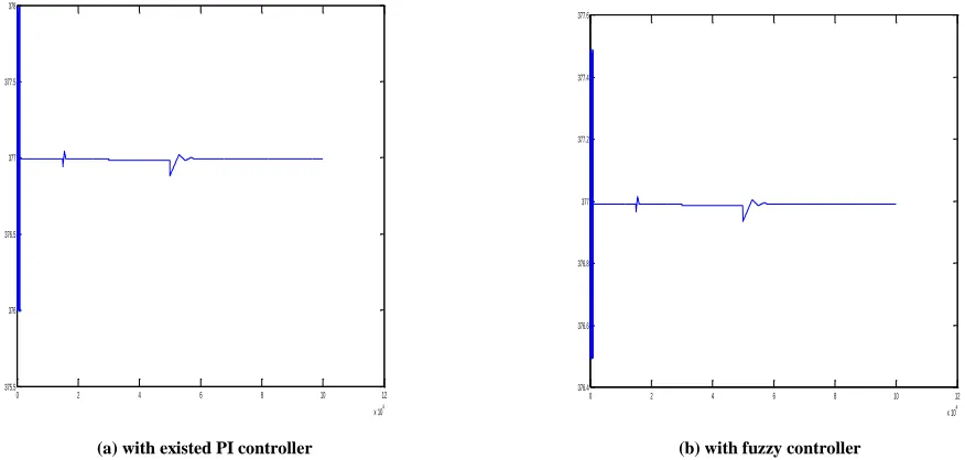
Case 1:Figure 12 (a) & (b) represents the grid angular
frequency with respect to the time period for the existed PI controller and proposed fuzzy controller respectively. The load varies in a step manner with active power component of 377W over a time period of 30s.
Case 2: Figure 13 (a) & (b) represents the angular
frequency at Point of Common Coupling (PCC) that varies with respect to the time period for existed PI controller and fuzzy controller respectively. The load power sharing is maintained at P1=377 W up to a time period of 40 s.
e
e
N
H
N
M
N
S
Z
E
P
H
P
M
P
S
NH
N
H
N
H
N
H
N
H
N
M
N
M
Z
E
NM
N
H
N
H
N
H
N
M
N
S
Z
E
P
S
NS
N
H
N
H
N
M
N
S
Z
E
P
S
P
M
ZE
N
H
N
M
N
S
Z
E
P
S
P
M
P
H
PH
N
M
N
S
Z
E
P
S
P
M
P
H
P
H
PM
N
S
Z
E
P
S
P
M
P
H
P
H
P
H
PS
Z
International Journal of Emerging Technology and Advanced Engineering
Website: www.ijetae.com (ISSN 2250-2459, ISO 9001:2008 Certified Journal, Volume 5, Issue 1, January 2015)
[image:6.612.64.544.121.609.2]251
[image:6.612.68.543.136.362.2]Fig 6: Simulink model of the proposed DG system.
International Journal of Emerging Technology and Advanced Engineering
Website: www.ijetae.com (ISSN 2250-2459, ISO 9001:2008 Certified Journal, Volume 5, Issue 1, January 2015)
[image:7.612.79.541.150.391.2]252
Fig 9: Simulink Model of Fuzzy based controller
Fig. 10: Inverter 1 voltages
(
V
a,V
b,V
c)
Fig 11: Inverter 2 voltages (
1 1 1
,
,
b ca
V
V
[image:7.612.322.548.422.627.2]International Journal of Emerging Technology and Advanced Engineering
Website: www.ijetae.com (ISSN 2250-2459, ISO 9001:2008 Certified Journal, Volume 5, Issue 1, January 2015)
253
Case 1:
0 2 4 6 8 10 12
x 104 376.5
376.6 376.7 376.8 376.9 377 377.1 377.2 377.3 377.4 377.5
[image:8.612.80.545.166.391.2](a) With existed PI controller (b) with fuzzy controller
Fig 12: waveforms of grid angular frequency (rad/s) Vs time (secs) : (a) with existed PI controller (b) Proposed fuzzy system
Case 2:
0 2 4 6 8 10 12
x 104 375.5
376 376.5 377 377.5 378
0 2 4 6 8 10 12
x 104 376.4
376.6 376.8 377 377.2 377.4 377.6
(a) with existed PI controller (b) with fuzzy controller
Fig 13: waveforms of PCC angular frequency (rad/s) Vs time (secs) : (a) with existed PI controller (b) Proposed fuzzy controller
0 2 4 6 8 10 12
x 104 376
[image:8.612.94.532.444.653.2]International Journal of Emerging Technology and Advanced Engineering
Website: www.ijetae.com (ISSN 2250-2459, ISO 9001:2008 Certified Journal, Volume 5, Issue 1, January 2015)
254
Case 3: Figure 14 (a) & (b) represents the voltage
magnitude difference that varies with respect to the time period for existed PI controller and fuzzy controller
respectively .The waveform varies smoothly after 40s and it rises sharply at the instant of 15s.
0 2 4 6 8 10 12 x 104
-2 0 2 4 6 8 10
0 2 4 6 8 10 12 x 104 -2
-1 0 1 2 3 4 5
[image:9.612.100.533.182.375.2](a) with existed PI controller (b) with fuzzy controller
Fig 14: waveforms of voltage magnitude difference (volts) Vs time (secs) : (a) with existed PI controller (b) Proposed fuzzy controller
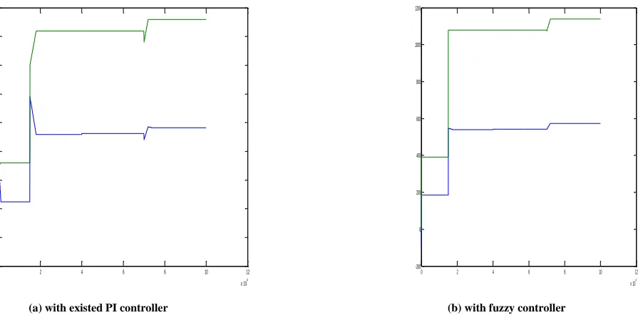
Case 4:Figure 15 (a) & (b) represents the active powers
P1 & P2 with respect to the time period for fuzzy controller
and existed PI controller respectively.
The active power P1 is started from 200W and the active
power P2 is started from 400W.
0 2 4 6 8 10 12
x 104 -100
0 100 200 300 400 500 600 700 800
0 2 4 6 8 10 12
x 104 -200
0 200 400 600 800 1000 1200
[image:9.612.94.545.443.664.2](a) with existed PI controller (b) with fuzzy controller
International Journal of Emerging Technology and Advanced Engineering
Website: www.ijetae.com (ISSN 2250-2459, ISO 9001:2008 Certified Journal, Volume 5, Issue 1, January 2015)
255
Case 5: Figure 16 represents the Reactive powers Q1 &
Q2 with respect to the time period for fuzzy controller and
existed PI controller respectively. The Reactive powers Q1 ,
Q2 starts from 105 VAR and 116 VAR.
0 2 4 6 8 10 12 x 104 -20
0 20 40 60 80 100 120 140
0 2 4 6 8 10 12
x 104
-20 0 20 40 60 80 100 120 140 160 180
[image:10.612.110.527.173.351.2](a) with existed PI controller (b) with fuzzy controller
Fig 16: waveforms of Reactive powers Q1 & Q2 (VAR) Vs time (secs) : (a) Proposed fuzzy controller (b) with existed PI controller
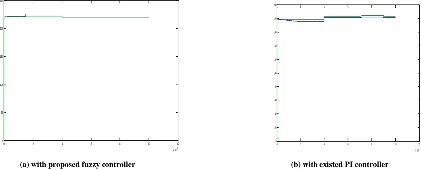
Case 6:Figure 17 represents the Voltage that varies with
respect to the time period for fuzzy controller and the
existed PI Controller respectively. The Voltage starts from 210V which rises exponential with respect to time period.
0 2 4 6 8 10 12 x 104
0 50 100 150 200 250
0 2 4 6 8 10 12
x 104 0
20 40 60 80 100 120 140 160 180 200
(a) with proposed fuzzy controller (b) with existed PI controller
[image:10.612.84.507.420.591.2]International Journal of Emerging Technology and Advanced Engineering
Website: www.ijetae.com (ISSN 2250-2459, ISO 9001:2008 Certified Journal, Volume 5, Issue 1, January 2015)
256
Case7: Figure 18 represents the Angular difference that
decays exponentially starting from 0.35 radians and obtains
a smooth response after 40s.
[image:11.612.89.532.183.384.2](a) with proposed fuzzy controller (b) with existed PI controller
Fig 18: Waveforms of Angular difference (rad) Vs time(secs):(a) Proposed Fuzzy controller, (b) with existed PI controller
Case 8:Figure 19 represents the Angular frequency that
varies with respect to time period. Sudden decrease in the
operating frequencies, helps to match the PCC voltage phase angle with the grid voltage phase angle.
3.5 4 4.5 5 5.5
x 104
376 376.5 377 377.5 378
3.5 4 4.5 5 5.5
x 104
376 376.5 377 377.5 378
a) with Proposed fuzzy controller b) with existed PI controller
Fig 19: Waveforms of Angular frequency (rad/sec) Vs time(secs): (a) Proposed fuzzy controller (b) with existed PI controller.
VI. CONCLUSION
A fuzzy logic based secondary controller is used for achieving the grid synchronization by integrating the distributed energy resource converters to microgrid. The simulation results with fuzzy logic controller helps in obtaining the quick response, low steady state error and reduces the harmonics with low ripple content.
The power factor is also improved near PCC and power quality has been increased by the influence of multiple types of DG sources in distribution generation system. Hence, the proposed fuzzy logic system has better performance for achieving grid synchronization than existed conventional PI controller.
0 2 4 6 8 10 12 x 104 -0.15
-0.1 -0.05 0 0.05 0.1 0.15 0.2 0.25 0.3 0.35
0 2 4 6 8 10 12 x 104 -0.15
International Journal of Emerging Technology and Advanced Engineering
Website: www.ijetae.com (ISSN 2250-2459, ISO 9001:2008 Certified Journal, Volume 5, Issue 1, January 2015)
257
REFERENCES
[1] ―Analysis of distributed generation systems, smart grid technologies and future motivators influencing change in the electricity sector‖ by Nur Asyik Hidyatullah, Blagojce Stojcevski, Aktar Kalam. [2] R.Lasseter, ―Microgrids‖, in Proc.IEEE Power Eng.soc.winter
meeting, 2002, pp. 305-308.
[3] Microgrid, a conceptual solution by R.H.Lasseter, Paolo Piagi University of Winsconsin-Madison,Winsconsin.
[4] Modeling,control and fault management of microgrids by Mehdi Moradian,Faramarz.
[5] Autonomous control of microgrids by Paolo Piagi member, IEEE,Robert H Lasseter, Fellow,IEEE.
[6] Droop control based power sharing for a microgrid with manifold Distributed Generations by Km Shobana, N Chitra.
[7] Phase locked loop control of Inverters in a microgrid by Matthevo supernant,IanHiskens and Giri Venkataraman.
[8] Y.A.I.Mohamed and A.A.Radwan, ―Hierarchial control system for robust microgrid operation and seamless mode transfer in active distribution systems‖, IEEE Trans. Smart Grid, vol. 2, no. 2, pp. 352–362, Jun. 2011.
[9] PLL for Single Phase Grid Connected Inverters by Mihail Antchev,Ivailo Pandev,Mariya Petkova,Eltimir Stoimenov, Angelina Tomova, Hristo Anchev.
[10] F.Blaabjerg,R.Teodorescue,M.Liserre, and A.V.Timbus, ―Overview of control and grid synchronization for distributed powergeneration systems, ― IEEE Trans. Ind. Electron., vol. 53, no. 5, pp. 1398– 1409,Oct. 2006‖.
[11] J.Rocabert, G.M.S. Azevedo, A.Luna, J.M.Gurrero, J.I.Candela and P.Rodriguez, ―Intelligent connection agent for three phase grid connected microgrids, ―IEEE Trans. Power Electron., vol. 26, no. 10, pp. 2993–3005,Oct. 2011.‖
[12] Autonomous Load sharing of Voltage source converters by Charles K Sao,Student member, IEEE, and Peter W Lehn,Member,IEEE. [13] J.Kim,J.M.Gurrero,P.Rodriguez,R.Teuoderescu and K.Nam, ―Mode
Adaptive control with virtual output impedances for an Inverter based flexible A.C.Microgrid‖ ,IEEE Trans. Power Electron., vol. 26, no. 3,pp. 689–701, Mar. 2011.
[14] Advanced SOGI-FLL scheme based on Fuzzy logic for single phase grid connected converters by Jin Sang Park,Than Hai Nguyen and Dong-choon Lee.
[15] M.C.Chandrokar,D.M.Divan, and R Adapa, ―Control of parallel connected inverters in standalone AC supply systems,‖ IEEE Trans. Ind.Appl., vol. 29, no. 1, pp. 136–143, Jan./Feb. 1993.
[16] ―Autonomous Load sharing of voltage source converters,‖ IEEE Trans. Power Del,vol 20,no.2, pp.1009-1016,Apr,2005.
[17] ―A new droop control method for the autonomous operation of distributed energy resource interface converters,‖ in Proc. IEEE ECCE, 2010, pp. 702–709.
[18] Introduction to Fuzzy logic by Claudio Moraga.
[19] Application of Fuzzy logic for the performance improvement of single phase Grid connected PWM Inverter by C.K.Panigrahi, Satyaranjan Jena,S.Satpathy,P.Parida,R.K.Pati and B.Chittibabu.
AUTHORS PROFILE
K.Venkata Sudheer Kumar has received his B.Tech in Electrical and Electronics Engineering in the year 2012 at QIS College of Engineering and Technology,Ongole.At Present, he is pursuing M.Tech in Power Electronics Specialization at Sri Vasavi Engineering College,West Godavari District.His Areas of interest are Power Electronics and Electrical Drives,Power Systems and Control Systems.
U. Chandra Rao hasreceived his Diploma in Electronics & Communication Engineering from SBTET, Hyd. in the year 1999 and B. Tech. degree in Electrical and Electronics Engineering from JNTU, Hyd. in the year 2004 and Master's degree with the specialization of High Voltage Engineering from JNTUK, Kakinada in the year 2010. Currently he is pursuing Ph.D. in JNTUK, Kakinada. At present he is working as an Associate Professor at Sri Vasavi Engineering College, W.G.Dt. His areas of interest are Power electronics, Electrical Drives, Power Systems, Renewable Energy Sources and Custom Power Devices.