MIMO WIRELESS AND MOBILE COMMUNICATIONS
Multi-user MIMO CDMA systems using complete
complementary sequences
C. Khirallah, P. Coulton, H. Rashvand and N. Zein
Abstract: The authors propose a novel use of complete complementary (CC) sequences for increased spectral efficiency in a multiple-input–multiple-output (MIMO) code division multiple access (CDMA) system. The new method overcomes many of the problems and limitations persistent in single-input–single-output (SISO) and proves that under the proposed MIMO CC-CDMA system, the capacity for the number of supported users increases linearly by the number of transmitters. The paper also shows that the MIMO CC-CDMA system demonstrates a superior performance over those using traditional Walsh spreading sequences (Walsh-CDMA). Results include the bit error rate comparison for CC-CDMA frequency selective fading channels and that of the Walsh-CDMA under flat fading channels.
1 Introduction
The new paradigm of multiple-input–multiple-output (MIMO) is a promising approach that can lead to significant bandwidth efficiency. The high spectral efficiency can be achieved by transmitting different signals on different transmit antennas simultaneously using the same frequency channel in conjunction with multiple receive antennas under an appropriate receive scheme[1, 2].
The spectral efficiency can be exploited in MIMO systems depending on a number of phenomena, including received power, noise, and co-channel interference. However, the multi-dimensional statistical behaviour of the MIMO fading channel is most significant to the system performance and also supports spatial multiplexing (SM) [3]. When used in conjunction with the vertical Bell Labs layered space time (VBLAST) that uses the same spreading sequence to transmit independent data streams from different antennas termed ‘sequence re-use’, the data rate increases, under narrowband and flat fading channel conditionsMtimes, whereMis the number of transmit antennas[4, 5].
However, using the code division multiple access (CDMA) with the commonly used Walsh sequences and VBLAST multi-user detector (MUD) suffers from high level multiple access interference (MAI) and significant inter-symbol interference (ISI) in wideband and frequency-selective fading channels resulting in severe degradation in system performance[6]. This is due to the corrupted initial orthogonality between Walsh sequences at the de-spread stage at the receiver. Many solutions have been proposed to
overcome this problem resulting in higher complexity. Some of these include:
(i) linear-chip equalisation combined with multiple non-linear parallel interference cancellation (IC)[7];
(ii) CDMA combined with orthogonal frequency division multiplexing (OFDM), which is capable of delivering high data rates in multipath environment by largely eliminating the effects of ISI [8]. However, owing to inter-carrier interference (ICI) in OFDM mobile communication systems, the bit error rate (BER) of the received signals is extremely sensitive to Doppler frequency shifts and carrier synchronisation errors [9];
(iii) Using alternative spreading sequences that exhibit resilience towards multipath time-dispersive effects. To this end, CC sequences have been considered[10]as a candidate for multi-carrier CDMA, offering much higher spreading efficiency (SE), a MAI-free operation in both down-link (synchronous channel) and up-link (asynchronous) and the ability to support multi-rate service with a low complexity rate-matching algorithm. This however only applies to single-input–single-output (SISO) systems with very few supported users. This is due to a restriction imposed on the length of the CC element sequence (KCC) by manageable signal levels in
the required multilevel (2KCC+1) digital modem.
This paper presents a new MIMO CC-CDMA system to overcome the aforementioned major limitations. Our MIMO CC-CDMA system applies the SM technique but instead of repeating a single sequence on different antennas its sets of CC sequences are reused on different transmit antennas to spread independent data streams. This technique, called ‘set re-use’, has the following benefits: (i) increasing the maximum number of supported users, which is no longer limited by the manageable signal levels in the digital modem, as shown in Table 1; (ii) by reducing the length of the CC element sequence and using multiple antennas in the MIMO CC-CDMA, it may be also possible to reduce the peak-to-average power ratio ( PAPR), and hence, the increased power efficiency of the power amplifier, meaning that the average radiated power is reduced in order to avoid the nonlinear distortion of transmitted signal[11]. Table 1 shows how the proposed MIMO CC-CDMA enables us to increase the number of supported users, while
E-mail: [email protected]
C. Khirallah and P. Coulton are with the Department of Communication Systems, University of Lancaster, B Floor, INFOLAB 21, South Drive, Lancaster LA1 4WA, UK
H. Rashvand is with the School of Engineering, University of Warwick, Coventry, CV4 7AL, UK
N. Zein is with the Telecommunications Consulting Department, NEC Europe Ltd, SL1 3UA, UK
rThe Institution of Engineering and Technology 2006
IEE Proceedingsonline no. 20050404 doi:10.1049/ip-com:20050404
maintaining the signal level, or equally to reduce the required modem complexity while maintaining the same number of users.
The rest of this paper is organised as follows: Section 2 presents, firstly, the generation of CC sequences, and then explains the ideal correlation properties of CC sequences compared to those of Walsh and Gold sequences. This comparison provides an indication of the likely system interference and forms the basic criteria for the selection of CC spreading sequences for wideband MIMO CDMA mobile systems. Section 3 presents the general model of the proposed MIMO CC-CDMA system and followed by a detailed example of 2transmit-2receive (2,2) CC-CDMA system. This includes a detailed description of how MAI, ISI and spatial interference (SPI) cancellation is achieved. Section 4 provides the simulation parameters for two comparable CC-CDMA and Walsh-CDMA simulation models, and the simulated BER performance. Finally conclusions are presented in Section 5.
2 Complete complementary sequences sets
The origin of CC sequences can be traced back to the 1960s, when Turyn [12]and Taki et al. [13]described a class of binary sequences, whose elements are either 1 or +1, and whose auto-correlation function is zero for all even (2-mulitple) shifts except the zero shift. These sequences have been called even-shift orthogonal sequences. Suehiro [14]extended the concept to the generation of CC sequence families/sets whose auto-correlation function is zero for all even and odd shifts except the zero shift and whose cross-correlation function, for any pair, is zero for all possible shifts. According to[14]in order forNsets, each made up ofNsequences, to be CC sequences of orderNthey must satisfy: (i) the sum of theNauto-correlation functions, for each set, is zero for any shift, except the zero shift (this set is called ‘auto-complementary sequence of orderN’); (ii) the sum of theNcross-correlation functions, between two sets ofNsequences, is zero for any shift (each of these two sets is called ‘cross-complementary sequence of orderN’).
2.1
Generating CC sequences of order N
using cross-orthogonal sequences of length
KCC
¼
N
2CC sequences can be constructed using Hadamard matrices [5], such as anN-dimensional orthogonal matrixAN, which is
generated recursively using the Kronecker product of a core matrixA2(22) andAn/2matrix as shown in (1) and (2).
AN ¼A2AN=2 ð1Þ
AN ¼
AN=2 AN=2 AN=2 AN=2
ð2Þ
whereA1is positive waveform (+1),AN=2 is the
comple-ment ofAN/2,N¼2kandk¼1, 2,y, log2N.
The following steps are used to generate CC sequences of lengthN2:
Constructing an auto-orthogonal sequence of lengthN2. Let D be a sequence of length N2 that is constructed by linking all rows of a Hadamard matrixAN(NN), which is
given in (2).
D¼ ða11; a12; . . .; a1N; a21; . . .;aN1; . . .; aNNÞ
ð3Þ SinceAN(NN) is orthogonal matrix, the auto-correlation
function ofDis zero for allN-multiple shifts except the zero shift.
Constructing a set of N cross-orthogonal sequences of length N2. Let [A]1, [A]2,y, [A]N be the rows of the
Hadamard matrix AN(NN) and now let us make
sequences of length N2 as the rows of orthogonal matrix Bgiven by
B¼ B1 B2 .. . BN 2 6 6 6 6 4 3 7 7 7 7 5¼
a11½A1; a12½A2; . . .; a1N½AN
a21½A1; a22½A2; . . .; a2N½AN ..
.
aN1½A1; aN2½A2; . . .; aNN½AN 2 6 6 6 6 4 3 7 7 7 7 5
ð4Þ It can be shown that sinceBandAare orthogonal matrices, the set of B1,B2,y,BN are both auto-orthogonal and
cross-orthogonal sequences of lengthN2.
2.2
Constructing N sets of CC sequences of
order N using auto-orthogonal sequences of
length N
2Using sequences in (4) and a Hadamard matrixAN(NN),
we can constructNsequences of lengthN2as shown in (5).
wij¼ ðbi1aj1; bi2aj2; . . .; biNajN;
bið1þNÞaj1; bið2þNÞaj2; . . .; bið2NÞajN;
.. .
biðN2ð1þNÞÞaj1; biðN2ð2þNÞaj2; . . .; biN2ajNÞ ð5Þ wherejandi¼1, 2,y,N. From (5) each set of sequences
fwi1;. . .;wiNg forms an auto-complementary sequence of order N, and any two of the generated N sets fw11;. . .;w1Ng;. . .,fwi1;. . .;wiNg,fwN1;. . . ;wNNg satisfy the property of the cross-complementary sequence of order N, where wij is a CC element sequence of
[image:2.595.46.286.68.150.2]lengthN2.
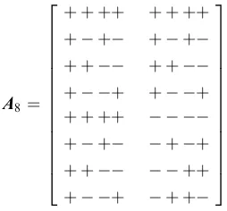
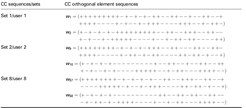
Table 2 shows a selected number of the eight sets of CC sequences (the first two sequences of each set), for a set size 8 and sequence length 64. These sequences are generated using an 88 Hadamard matrix given in (6).
A8¼
þ þ þþ þ þ þ þ þ þ
þ þ þþ þ þ þ þ þ þ þ þ þþ
þ þ þ þ þ þ
þ þ þþ þ þ 2 6 6 6 6 6 6 6 6 6 6 6 6 6 4 3 7 7 7 7 7 7 7 7 7 7 7 7 7 5
ð6Þ Table 1: Ability of the proposed MIMO CC-CDMA to either
increase number of users or reduce the complexity of the required multilevel digital modem
Element sequence length (KCC)
Number of users (M ffiffiffiffiffiffiffiffiffiKCC
p
)
Antenna structure (M,P)
Signal multilevel in digital modem (2KCC+ 1)
16 4 (1, 1) 33 16 8 (2, 2) 33
[image:2.595.365.492.651.769.2]2.3
CC sequences correlation properties
CC sequences exhibit the following fundamental differences compared to traditional CDMA spreading sequences such as (Gold sequences, m-sequences, Walsh Hadamard sequences, etc):
The mutual orthogonality of CC sequences is observed between ‘sets’ (sets of element sequences) instead of between single element sequences as for other spreading sequences such as Gold and Walsh sequences. In other words, for the proposed CC-CDMA system every user will be assigned one set of sequences, where the total number of available sets is defined as
F ¼N ¼ ffiffiffiffiffiffiffiffiKCC p
¼2j ð7Þ
where,j¼1, 2,yis a positive integer.
CC sequences exhibit unique correlation properties with zero cross correlation and zero out-of-phase autocorrelation are ensured for any relative shifts between two sequences. The auto-correlation function (cXXð Þi ) of a set X of CC sequences is defined, in (8), as the sum of the auto-correlation functions for all element sequences in X
cXXðiÞ ¼
P
NCC
n¼1
P
KCCi
k¼1
wnðkÞwnðkþiÞ¼0; 1iKCC1
P
NCC
n¼1
P
KCCþi
k¼1
wnðkÞwnðkiÞ¼0; 1KCCi 1
P
NCC
n¼1
P
KCC
k¼1
wnðkÞwnðkÞ ¼KCCNCC; i¼0
8 > > > > > > > > > > < > > > > > > > > > > :
ð8Þ
n¼1, 2,y, NCC (¼pffiffiffiffiffiffiffiffiKCC) is the number of element
sequences per set. k¼1, 2,y,KCC and i¼0,71, 72,y,7(KCC1) is an integer that represents the
number of cyclic shifts (given by chip-periodtC) for each
element sequence, and wn(k) is the kth chip of the nth
element sequence. From (8), it can be seen that cXX(i)
equals zero for all time shifts except the zero-shift, thus indicating the possibility of reduced level of ISI in multipath fading channels.
For CC sequences the cross-correlation function (cXY(i))
between two consecutive CC setsXandYis defined in (9) as the sum of all cross-correlation functions between any
pair of element sequences in those sets.
cXYðiÞ ¼
P
NCC
n¼1 P
KCCi
n¼1
wnðkÞwnþNCCðkþiÞ ¼0; 0iKCC1
P
NCC
n¼1 P
KCCþi
k¼1
wnðkÞwnþNCCðkiÞ ¼0; 1KCCi 1 8
> > > > > < > > > > > :
9 > > > > > = > > > > > ;
ð9Þ From (9), it is noted that cXY(i) equals zero for all time
shifts, which indicate a high reduction in the MAI between different CC sequences that belongs to different users. It is assumed that the relative delay between multipaths takes multiple chips. However, if this assumption does not hold it can be shown that the resultant MAI level is far less than that of traditional CDMA systems[10]. It is appropriate to refer to sequence sets which satisfy (8) and (9) as orthogonal CC sequences. For example, consider X ¼ ½w1;w2 ¼
1;1;1;1;1;1;1;1
½ and Y¼ ½w3;w4 ¼½1;1;1;1;
1;1;1;1. Hence, cXX¼cw1w1þcw2w2 ¼ ½0;0;0;
8;0;0;0 cYY ¼cw3w3þcw4w4¼ ½0;0;0;8;0;0;0 and
cXY¼cw1w3þcw2w4¼ ½0;0;0;0;0;0;0.
Comparing (8) and (9) to the three possible valuest nð Þ;
1;t nð Þ 2 of the auto-correlation and cross-correla-tion funccross-correla-tions, indicated in[15], for a set ofNþ1 Gold sequences [16] of length N¼2n1. These values are given by
t nð Þ ¼ 1þ2
nþ1
2 fornodd
1þ2nþ22 forneven
ð10Þ
From above comparison, one can expect the perfor-mance of a CC-CDMA system to surpass that of Gold-CDMA. This observation agrees with results obtained in [10]. Other sequences, which are of great interest in synchronous spread spectrum networks, are the m-sequences, since the correlation value between differ-ent shifts for each m-sequence is almost zero. However, the m-sequences may still be prone to large cross-correlation values. Walsh obtained the following lower bound on the cross-correlation values between any pair of binary sequences of periodTin a set ofMsequences[15]
Rcð Þ k T
ffiffiffiffiffiffiffiffiffiffiffiffiffiffiffiffi
M1
MT1 r
[image:3.595.93.508.58.240.2]ffipffiffiffiffiT ð11Þ Table 2: A selected number of CC sequences, for an element sequence of length 64, generated using
an 88 Hadamard matrix
CC sequences/sets CC orthogonal element sequences
Set 1/user 1 w1¼ ðþ þ þ þ þ þ þ þ þ þ þ þ þ þ þ þ þ þ þ þ
þ þ þ þ þ þ þ þ þ þ þ þ þ þ þ þ Þ
w2¼ ðþ þ þ þ þ þ þ þ þ þ þ þ þ þ þ þ þ þ þ þ
þ þ þ þ þ þ þ þ þ þ þ þ þ þ þ þÞ
Set 2/user 2 w9¼ ðþ þ þ þ þ þ þ þ þ þ þ þ þ þ þ þ þ þ þ þ
þ þ þ þ þ þ þ þ þ þ þ þ þ þ þ þÞ
w10¼ ðþ þ þ þ þ þ þ þ þ þ þþ
þ þ þ þ þ þ þ þ þ þ þ þ þ þ þ þ Þ
Set 8/user 8 w57¼ ðþ þ þ þ þ þ þ þ þ þ þ þ þ þ þ þ þ þ þ þ
þ þ þ þ þ þ þ þ þ þ þ þ þ þ þ þÞ
w58¼ ðþ þ þ þ þ þ þ þ þ þ þ þ
Since each user in the proposed CDMA system is assigned a signature sequence comprising a set of element sequences, as shown in Table 2, the processing gain of the CC sequences equals to the aggregate length of all element sequences in a set and can be given by
PGCC¼KCCNCC ð12Þ Those element sequences can be sent to the receiver either using parallel multi-carrier (MC) transmission mode, where all element sequences are transmitted using different carriers or using serial transmission mode, where all element sequences are sent using the same carrier. In this paper, a synchronous serial-transmission mode is adopted.
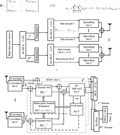
[image:4.595.100.504.297.754.2]3 MIMO CC-CDMA system model
Figure 1 shows a block diagram of the proposed (M,P) MIMO CC-CDMA system model, where M and P represent the number of transmit and receive antennas. At the transmitter, information bits are de-multiplexed into M parallel streams. Each stream is modulated then further de-multiplexed intoFparallel sub-streams, as shown in (13), before being spread by F sets of CC sequences.
B¼
bð1;1;1Þ . . . bð1;F;KCCÞ
.. .
. . .
.. .
bðM;1;1Þ . . . bðM;F;KCCÞ
2 6 4
3 7
5 ð13Þ
where bðm;f;jÞ represents thejth symbol, (j¼1, 2,y,KCC)
that will be spread using the element sequences of thefth set. Finally the spread signals are summed and normalised, with respect to the signal energy, before being simulta-neously transmitted over M antennas. The transmitted signal over themth antenna is given by
tm¼ X
F
f¼1
XKCC
j¼1
bðm;f;jÞwððf1ÞFþ1Þðtðj1Þ tcÞ;. . .; (
XF
f¼1
XKCC
j¼1
bðm;f;jÞwðfFÞðtðj1Þ tcÞ )
ð14Þ
The multipath channel impulse response is given by
h tð Þ ¼X P
p¼1
XL
l¼1
XM
m¼1
hðp;l;mÞð Þt dðtltCÞ ð15Þ
wherehp;l;mis the channel coefficient, with zero mean and Rayleigh fading distribution, for the sub-channel between thepth receive antenna andmth transmit antenna over the lth multipath (wherel¼1, 2,y,L). The received signal at
thepth antenna is given by
rp¼ XM
m¼1
XL
l¼1
tmðt ðl1Þ tCÞ hðp;l;mÞþnp ð16Þ
np represents AWGN with zero mean and variance s2. Note that for the simplicity of the following derived equations, the noise powers2is assumed to be zero.
At the receiver, signals at each antenna are de-spread using F set correlators then normalised with PGCC.
Consider an (FP) matrixG G
½ fp¼g ðjÞ fp
¼ PM m¼1
bðm;f;jÞhðp;j;mÞ j¼1
PL l¼1
PM m¼1
bðm;f;ðjlÞþ1Þhðp;l;mÞ 2jKCC 8
> > > > < > > > > :
ð17Þ wheregfprepresent the signal at the output of thefth set’s
correlator that belongs to thepth branch of the receiver.gfp
is a single dimensional matrix (dimensions (1KCC)), and gfp(j¼1) gives the 1st element of matrixgfp. The resulting
signals in (17) are then passed toFMUDs, each consisting of the following. (i) A channel power profile estimator; including multipath delays and power ratios. (ii)Pchannel matched filters. The input signals for the pth filter are multiplied by the complex conjugate of the 1st path (l¼1) channel coefficients at thepth receive antenna and are given in the following
H
½ pl¼hpl¼½hp11;. . .; hp1m T
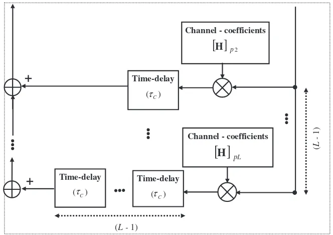
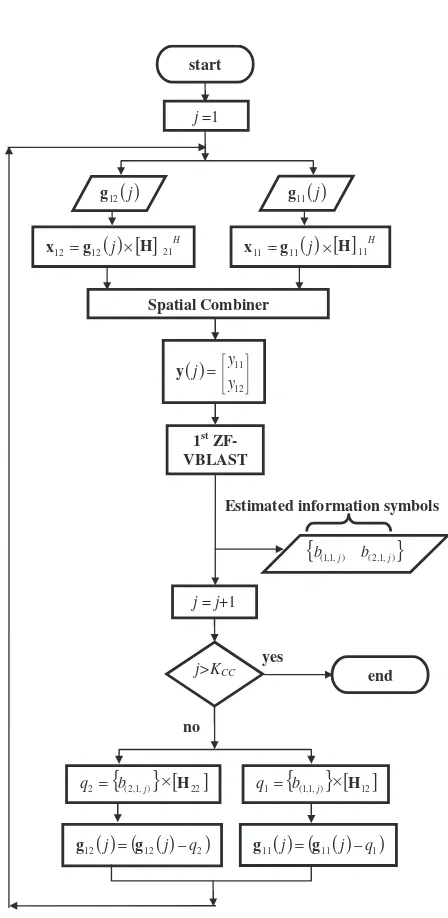
ð18Þ whereHis theðPLMÞdimensions multipath channel matrix with elementshp;l;m.Tstands for the transpose. (iii) A ZF VBLAST detector to eliminate SPI between users sharing the same set of CC sequences and transmitted from different antennas. (iv) A feedback stage, shown in Figs. 1 and 2, that utilises a successive interference canceller (SIC) to eliminate ISI between the data symbols of signals, which are received over different paths in the channel and belong to the same user.
To explain the iterative operation of each MUD a detailed example of (2, 2) antenna CC-CDMA system with KCC¼4 chips andF¼2 sets, is illustrated in Figs. 3 and 4,
using the block diagram of the receiver and the flowchart of MUD operation, respectively.
At the 1st iteration (j¼1) and from (17) and (18) the following is obtained
X ½ fp¼x
ðjÞ fp ¼h
pl
XM
m¼1
bðm;f;jÞhðp;1;mÞ ð19Þ
where xfpis the output of thefth set weighted by thepth
channel matrix that corresponds to thepth receive antenna. The multipath components of the 1st set which form the inputs of the 1st ZF-VBLAST detector[4]are given by
Y
½ fm¼yfm¼ XP
p¼1
xðmÞfp ð20Þ
where yfm is the mth input of the fth ZF-VBLAST. The
VBLAST algorithm requires the M-by-M set-channel correlation matrix defined as
Rf ¼ XP
p¼1
HHpSfHp ð21Þ
where H is a Hermitian symmetric matrix and Sf is the L-by-L set correlation matrix for the fth set. The (i,j)th element ofSfis the inner product of theichip-delayed set
with that of the j chip-delayed set. For example, assume L¼2 multipaths, with the delay of the l¼1 multipath relative to the l¼2 multipaths is a single chip, then and from (8) and (9)
Sf ¼
cffð Þ0 cffð Þ1
cffð Þ1 cffð Þ0
" #
¼Ið22Þ ð22Þ
Equation (21) indicates that by using CC sequences (which have ideal correlation properties) Sf is simplified to an
identity matrix, which in turn reduces the complexity of calculatingRfas in (21). The reduction ofSfinto an identity
matrix also translates into cancellation of multipath interference, which implies that the VBLAST detectors now operate under flat fading channel conditions. This results in performance achieving a large fraction of the MIMO channel capacity[17].
The channel correlation matrix used in the ZF-VBLAST detector transfer the channel condition from frequency selective to flat fading, hence, the performance of
Time-delay
) (τ C
Channel - coefficients
[ ]
H p2+
Channel - coefficients
[ ]
H
pLTime-delay
)
( C
Time-delay
)
( C
+
(
L
-1)
(L - 1)
τ τ
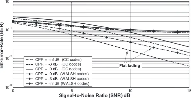
[image:5.595.130.462.520.754.2]CC-CDMA will approximate that of Walsh-CDMA in flat fading as shown in Fig. 5. Referring to (19)–(21) yields
Y¼RfbðfjÞ ð23Þ
wherebðfjÞ gives the estimated data symbols at the outputs
of thefth VBLAST detector at thejth iteration.bðfjÞis then scaled by the channel coefficients of the 2nd path as shown in (25).
H
½ 12¼h12¼½h121 h12m ð24Þ
Q ½ fp¼q
ðjÞ
fp ¼hpl XM
m¼1
bðm;f;jÞhðp;1;mÞ ð25Þ
In order to eliminate ISI of the next detection stages, signals in (25) are subtracted from those in (17) at the (j+1)th iteration to give the following
Z ½ fp¼z
ðjþ1Þ fp ¼g
ðjþ1Þ
fp q
ðjþ1Þ
fp ð26Þ
The iterative operation of the MUD is repeated for KCC
iterations.
[image:6.595.244.532.28.750.2]4 Simulation models and numerical results
Table 3 provides the simulation parameters for comparable (2, 2) CC-CDMA and Walsh-CDMA system models. The multipath channel model is set up with the following assumptions and parameters: (i) a frequency-selective Rayleigh fading distribution [18] and uncorrelated fading between the antenna pairs; (ii) perfect channel estimation; (iii) each sub-channel hasL¼2 components with the 2nd path delayed bytC. The average-power ratio between the
two paths is defined as
channel-power-ratioðCPRÞ
¼ð2nd path power=1st path powerÞ ð27Þ The simulations assume an ideal modulation and demodu-lation process leaving the effects of multilevel carrier modulation and demodulation as a topic of future study.
Results shown in Fig. 5 are twofold: first, although the BER performance of Walsh-CDMA out performs that of
1st MUD
Despread Set 1
Despread Set 2
Channel Matched
Filter
[ ]
H11 H
Despread Set 1
Despread Set 2
VBLAST
Set 1
VBLAST
Set 2
-
--
-
From q11
Channel Estimator
Channel Matched
Filter
[ ]
H 21 H r1r2
g11
g21
g12
g22
y11
y12
y21
y22
From q21
From q12
From q22
z11
z12
Fe
ed
b
ac
k
Feed
bac
k
q11
q12
q21
q22
2nd MUD
Fig. 3 Receiver block diagram for a (2, 2) MIMO CC-CDMA system
start
( )j
11 g
( )j
12 g
j=1
Spatial Combiner
( )=
12 11
y y j
y
1st ZF-VBLAST
{
b(1,1,j) b(2,1,j)}
( ) ( 11( ) 1)
11 j = g j q g
( ) ( 12( ) 2)
12 j = g j q g
j>KCC yes
end
j = j+1
no
Estimated information symbols
( )
= 11 j
11 g
x
[ ]
H 11H{ }
(1,1,)[ ]
121= b j H
q
( )
= 12 j
12 g
x H 21H
{ }
(2,1,)2 b j
q =
[ ]
H22× ×
× ×
− −
[ ]
[image:6.595.128.461.30.279.2] [image:6.595.315.539.291.750.2]CC-CDMA, for CPR¼0 dB when SNR is under 8 dB and for CPR¼ 3 dB when SNR is under 6 dB, CC-CDMA illustrates a dramatic improvement in performance over the Walsh-CDMA system to such an extent that the CC-CDMA performance at CPR¼0 dB has only a mere 3 dB degradation from the Walsh-CDMA operating at a CPR¼ infinity dB. Second, although a drop in perfor-mance (E6 dB) for a CC-CDMA system operating at CPR¼0 dB compared to the case for flat fading channels, no IBER is present for any of the CPR values owing to the novel combination of CC sequences and the MUD, proposed in this paper, which effectively mitigate the effect of MAI, ISI and SPI sources.
The degradation in CC-CDMA performance is due to the use of a simple low-complexity single-looped recursive filter, at the feedback stage shown in Fig. 2, which while trying to cancel the ISI, between received data sub-streams caused by the time-dispersive effect of a frequency-selective fading channel, it does not cancel the noise. This results in the error propagation problem associated with the SIC algorithm[19]. Note that results in Fig. 5 are consistent with those obtained in[10].
A more advanced SIC is likely to result in less degradation in system performance for low SNR.
Figure 6 illustrates a comparison in BER performance for CC-CDMA usingKCC¼4, and 16. The results obtained
are threefold: first, approximately similar flat fading (CPR¼ infinity dB) performance; second, the resilience of CC-CDMA systems to an increased number of users (KCC¼16), when operating in frequency selective fading
channels (CPR¼0 dB), withE1 dB degradation compared withKCC¼4; finally, the results highlight the possibility of
creating a multi-rate and multi-user system that offers variable HDR services without compromising the accep-table error rate levels in the system[20].
5 Conclusions
In this paper a novel and practical MIMO CDMA architecture based on CC sequences has been proposed and simulated for different numbers of users and channel profile using BER as a measure of system performance. The
0 5 10 15
10-3 10-2 10-1 100
CPR = -inf dB (CC codes) CPR = -3 dB (CC codes) CPR = 0 dB (CC codes) CPR = 0 dB (WALSH codes) CPR = -3 dB (WALSH codes) CPR = -inf dB (WALSH codes)
B
it
-E
rro
r-R
a
te
(
B
E
R
)
Signal-to-Noise Ratio (SNR) dB
Flat fading
[image:7.595.132.465.34.206.2]Fig. 5 BER against SNR for (2, 2) Walsh-CDMA and CC–CDMA systems with similar user capacity and processing gain
Table 3: Simulation parameters of both MIMO CC-CDMA and MIMO Walsh-CDMA systems
Simulation parameters CC-CDMA Walsh-CDMA
Element sequence length KCC¼4 KW¼8 Processing gain PGCC¼8 PGW¼8
Number of users supported 4 4 (50% system load) Sub-streams data rate
(ksymbol/s)
SRCC¼960 SRW¼480
Transmit chipping rate (Mchip/s)
3.84 3.84
Total data rate (Mbit/s) 7.68 7.68
0 5 10 15
10-3 10-2 10-1 100
CPR= -inf dB (Kcc =4) CPR= -3dB (Kcc =4) CPR= 0dB (Kcc =4) CPR= -inf dB (Kcc =16) CPR= -3 dB (Kcc =16) CPR= 0 dB (Kcc =16)
B
it-E
rro
r-R
a
te
(B
E
R
)
Signal-to-Noise Ratio (SNR) dB
Flat fading
[image:7.595.47.286.429.552.2] [image:7.595.129.465.576.756.2]results achieved are twofold. First, the proposed MIMO CC-CDMA system overcomes the problem associated with the low user-capacity of SISO CC sequences, by using the ‘set re-use’ technique that supports multi-user transmission mode of up to MF users in a MIMO antenna, or M times higher total data rate compared to a SISO CC-CDMA system. Secondly, the MIMO CC-CC-CDMA system significantly outperforms the traditional MIMO Walsh-CDMA systems in a frequency-selective fading environment with BER performance of MIMO CC-CDMA in frequency selective fading approaching that of MIMO Walsh-CDMA in flat fading channel conditions. Overall this work highlights the significant opportunities that are presented to designers of MIMO systems by utilising the inherent properties of CC sequences.
6 References
1 Foschini, J.G., and Gans, J.M.: ‘On limits of wireless communications in a fading environment when using multiple antennas’,Wirel. Pers. Commun., 1998,6, (3), pp. 311–335
2 Goldsmith, A., Jafar, A.S., Jindal, N., and Vishwanath, S.: ‘Capacity limits of MIMO channels’,IEEE J. Sel. Areas Commun., 2003,21, (5), pp. 684–702
3 Paulraj, A., Nabar, R., and Gore, D.: ‘Introduction to space-time wireless communications’ (Cambridge University Press, 2003) 4 Golden, G.D., Foschini, J.G., Valenzuela, A.R., and Wolniansky,
W.P.: ‘Detection algorithm and initial laboratory results using V-BLAST space–time communication architecture’, Electron. Lett., 1999,35, (1), pp. 14–16
5 Huang, H., Viswanathan, H., Blanksby, A., and Haleem, A.M.: ‘Multiple antenna enhancements for a high rate CDMA packet data system’,J. VLSI Signal Process. Syst. Signal Image Video Technol., 2002,30, pp. 55–69
6 Boubaker, N., Letaief, B.K., and Murch, D.R.: ‘Performance of BLAST over frequency-selective wireless communication channels’,
IEEE Trans. Commun., 2002,50, (2), pp. 196–199
7 Leus, G., Petre, F., and Moonen, M.: ‘Space–time chip equalization for space-time coded downlink CDMA’. Proc. IEEE Int. Conf. on Communications (ICC’02), New York, USA, 28 April–2 May 2002, pp. 568–572
8 Ng, W.K, Cheng, S.R., and Murch, R.D.: ‘A simplified bit allocation for V-BLAST based OFDM MIMO systems in frequency selective fading channel’. Proc. IEEE Int. Conf. on Communications (ICC’02), New York, USA, 28 April–2 May 2002, pp. 411–415
9 Li, J., and Kavehrad, M.: ‘Effects of Time Selective multipath fading on OFDM systems for broadband mobile Applications’, IEEE Commun. Lett., 1999,3, (12), pp. 332–334
10 Chen, H.H., Yeh, F.J., and Suehiro, N.: ‘A multicarrier CDMA architecture based on orthogonal complementary codes for new generations of wideband wireless communications’,IEEE Commun. Mag., 2001,39, (10), pp. 126–135
11 Popovic, M.B.: ‘Spreading sequences for multicarrier CDMA systems’,IEEE Trans. Commun., 1999,47, (6), pp. 918–926 12 Turyn, R.: ‘Ambiguity function of complementary sequences’,IEEE
Trans. Inf. Theory, 1963,IT-9, pp. 46–47
13 Taki, Y., Miyakawa, H., Hatori, M., and Namba, S.: ‘Even-shift orthogonal sequences’, IEEE Trans. Inf. Theory., 1969, IT-15, pp. 295–300
14 Suehiro, N., and Hatori, M.: ‘N-shift cross-orthogonal sequences’,
IEEE Trans. Inf. Theory, 1988,IT-34, pp. 143–46
15 Dinan, H.E., and Jabbari, B.: ‘Spreading codes for direct sequence CDMA and wideband cdma cellular networks’, IEEE Commun. Mag., 1999,36, (9), pp. 48–54
16 Gold, R.: ‘Optimal binary sequences for spread spectrum multi-plexing’,IEEE Trans. Inf. Theory, 1967,IT-13, pp. 619–21
17 Foschini, G., Golden, G., Valenzuela, R.A., and Wolniansky, W.P.: ‘Simplified processing for wireless communications at high spectral efficiency’, IEEE J. Sel. Areas Commun., 1999, 17, pp. 1841–1852
18 Dent, P., Bottomley, G.E., and Croft, T.: ‘Jakes fading model revisited’,Electron. Lett., 1993,29, (13), pp. 1162–1163
19 Shen, C., Zhuang, H., Dai, L., and Zhou, S.: ‘Detection algorithm improving V-BLAST performance over error propagation’,Electron. Lett., 2003,39, (13), pp. 1007–1008