i
“I/We hereby declared that I/we have read through this report
and found that it has comply the partial fulfillment for awarding the degree of Bachelor of Mechanical Engineering (Design and Innovation)”
Signature :
Supervisor Name : Mr. Shafizal Bin Mat
ii
DESIGN AND ANALYSIS OF OPTICAL MOUSE USING BOOTHROYD DEWHURST DFMA METHODOLOGY
KHAIRUL AIDIL BIN NORDIN
This report is submitted as partial fulfillment of the requirement for the award of
Bachelor of Mechanical Engineering (Design and Innovation)
Faculty of Mechanical Engineering Universiti Teknikal Malaysia Melaka
iii
“I hereby declared that this report is a result of my own work except for the excerpts that have been cited clearly in the references”
Signature : ………
Name : Khairul Aidil Bin Nordin
iv
Especially to my beloved parents, My lovely brothers, My respectfully lecturers, Also my faithfully friends,
v
ACKNOWLEDGEMENT
In this great opportunity, I would like to thank Allah for providing me strengths to completing this report. Here, I would like to acknowledge with appreciation to all those people who helped me numerously during completing this project.
In a particular, I would like to convey my sincere thank you to my supervisor Mr. Shafizal Bin Mat, for giving me chance to do the project under his supervision. I also would like to thank to him for teaching me more in mechanical engineering subjects especially works for my topic. He also guided me and given advised based on his experience during my progress of this project. His constant encouragement and guidance had brought me to completing my project.
vi
ABSTRACT
vii
ABSTRAK
viii TABLE OF CONTENT
CHAPTER TITLE PAGE
DECLARATION i
ACKNOWLEDGEMENT v
ABSTRACT vi
ABSTRAK vii
CONTENTS viii
LIST OF TABLES xii
LIST OF FIGURES xiv
LIST OF APPENDIX xv
CHAPTER 1 INTRODUCTION 1
1.1 General 1
1.2 Objectives 2
1.3 Scope Of The Project 2
1.4 Problem Statement 3
CHAPTER 2 LITERATURE REVIEW 4
2.1 Design for Manufacturing and Assembly
(DFMA) 4
2.2 history and Background of design assembly
(DFMA) 7
2.3 Advantage of applying DFMA 9
2.4 Example How DFMA Apply 10
2.5 Overview of DFMA 14
2.5.1 guideline for DFM 14
2.5.2 rules for DFM 15
2.5.3 Basic DFA Guidelines 16
2.5.3.1 Design Guideline for HART
ix & Fastening
2.6 DFMA method 19
2.7 Various DFMA Method 21
2.7.1 The lucas Method 21
2.7.1.1 The Evaluation procedure 23 2.7.1.2 Improvement of Design 24 2.7.1.3 The Lucas DFA Evaluation
example 24 2.7.2 Assembly Evaluation Method (AEM) 27 2.7.2.1 The Evaluation Procedure 29 2.7.2.2 Improve of Design 30 2.7.2.3 The Hitachi,s AEM Method
example 30 2.7.3 The Boothroyd Dewhurst Method 31 2.7.3.1 Evaluation Procedure 32 2.7.3.2 Improvement of Product 33 2.7.3.3 Boothroyd Dewhurst DFMA
example 33
2.8 summary 37
CHAPTER 3 METHODOLOGY 39
3.1 Introduction 40
3.2 Literature Review 41
3.3 Conceptual Design 41
3.4 selection Design 41
3.5 CAD Drawing (Detail Design) 42
3.6 DFMA Analysis
3.6.1 Alpha and Beta symmetric
3.6.2 Design Guideline for Part Handling 3.6.3 Design Guideline for Insertion &
Fastening 45
x
CHAPTER 4 DFMA ANAYSIS FOR EXISTING PRODUCT 49
4.1 Introduction 49
4.2 Product Description 49
4.3 Analysis of the existing product (Manual) 53
4.3.1 Assembly Flow Chart 54
4.3.2 The Process and Material Selection 56
4.3.3 Theoretical Part 64
4.3.4 Alpha and Beta symmetric 65
4.3.5 Handling and Insertion Time 66
4.4 Analysis of the existing product (DFMA Software) 68 4.4.1 Design for Manufacture (DFM) 68 4.4.2 Design for Assembly (DFA) 73 CHAPTER 5 CONCEPTUAL DESIGN AND SELECTED DESIGN 77
5.1 Introduction 77
5.1.1 Proposed Design 78
5.1.2 Selection Design 83
5.2 Detail drawing 86
5.2.1 Drawing Design for Existing Design 86 5.5.2 Drawing Design for New Design 87
CHAPTER 6 DFMA ANAYSIS FOR NEW DESIGN 88
6.1 Introduction 88
6.2 Analysis of the New Design (Manual) 88
6.2.1 Assembly Flow Chart 91
6.2.2 The Process and Material Selection for New design 92
6.2.3 Theoretical Part 98
xi
6.2.5 Handling and Insertion Time 99 6.3 Analysis of the new design (DFMA Software) 101 6.3.1 Design for Manufacture (DFM) 101
6.4 Design for Assembly (DFA) 103
CHAPTER 7 DISCUSION 106
7.1 Introduction 106
7.2 Comparison of Manual and Software analysis 106 7.3 Comparison of Existing Design and New Design 110
CHAPTER 8 CONCLUSION AND SUGGESTION 113
8.1 Conclusion 113
8.2 Suggestion and Recommendation 114
REFERENCE 115
APPENDIXES 117
APPENDEX A1 117
APPENDEX A2 118
APPENDEX B1 119
APPENDEX B2 120
APPENDEX C1 121
xii
LIST OF TABLE
NO TABLE PAGE
2.1 DFMA Software Average Reductions 9
(Source: Boothroyd Dewhurst, Inc)
2.2 DFA analysis result 11
(Source: Geoffrey Boothroyd, 1994)
2.3 Result after DFA analysis 13
(Source: Geoffrey Boothroyd, 1994)
2.4 The available commercial DFMA method 19
(Source:Stephen ESkilandar, 2001)
2.5 Evaluating the design efficiency of Piston 35 (Source: Redford Alan, J. Chal, 1990)
2.6 Evaluating the design efficiency of the re-designed piston 37 (Source: Redford Alan, J. Chal, 1990)
3.1 Table for computation of Design efficiency 43 (Source: Redford Alan, J. Chal, 1990)
3.3 Manual Handling 46
(Source: Geoffrey Boothroyd, 1994)
3.4 Manual Insertion 47
(Source: Geoffrey Boothroyd, 1994)
xiii
4.2 Alpha & Beta of Optical Mouse part 65
4.3 Analyze Handling and Insertion Time 66
4.4 DFM Software Concurrent Costing Totals 71
4.5 Totals Costing per Part of each part 72
4.6 Executive Summary for DFA 74
4.7 Total Analysis for DFMA 75
4.8 DFMA summary result 76
5.1 Pugh’s concept selection method 84
6.1 Theoretical Part for New Design 98
6.2 Alpha & Beta of Optical Mouse part 99
6.3 Analyze Handling and Insertion Time 100
6.4 DFM Software Concurrent Costing Totals 101 6.5 Totals Costing per Part of each part 102
6.6 Executive Summary for DFA 103
6.7 Total Analysis for DFMA 104
6.8 DFMA summary result 105
7.1 Result of Manual Analysis 109
xiv
LIST OF FIGURE
NO. FIGURE PAGES
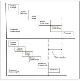
Figure 2.1 Traditional product development compared to concurrent engineering
(Source: Stephen Eskilandar, 2001) 6 Figure 2.2 Proposed original design of Motor Drive assembly
(Source: Geoffrey Boothroyd, 1994) 10 Figure 2.3 Redesign of Motor Drive assembly after DFA
(Source: Geoffrey Boothroyd, 1994) 12 Figure 2.4 The Lucas DFMA procedure
(Source: H J Bullinger and M Richter, 1991) 22 Figure 2.5 Lucas evaluation method on existing design
(Source: Redford Alan, Jan Chal, 1994) 25 Figure 2.6 Lucas evaluation method on redesign product
(Source: Redford Alan, Jan Chal, 1994) 26 Figure 2.7 The Hitachi’s AEM procedure
(Source: www.ami.ac.uk/ami4813_dfx/u03/s01/index.asp) 28 Figure 2.8 Assemblability evaluation and improvements
(Source: Redford Alan, J. Chal, 1990) 30 Figure 2.9 A piston-assembly design
(Source: Redford Alan, J. Chal, 1990) 34
Figure 2.10 An improved piston design
(Source: Redford Alan, J. Chal, 1990) 36
Figure 3.1 Project Flow Chart 40
Figure 3.2 Alpha & Beta rotational symmetric guideline
(Source: Geoffrey Boothroyd 1991) 44
xv
Figure 4.2 Top cover of Optical Mouse 50 Figure 4.3 Middle cover of Optical Mouse 51 Figure 4.4 Bottom cover of Optical Mouse 51 Figure 4.5 Scroll Wheel with rubber 52 Figure 4.6 Printed circuit board (PCB) of optical Mouse 52 Figure 4.7 Disassembly view for Optical Mouse 53 Figure 4.8 Assembly Process Flow for Existing Design 54 Figure 4.9 Process Flow for Bottom Cover (Base) 57 Figure 4.10 Process Flow for LED Reflector 58 Figure 4.11 Process flow for PCB Board 59 Figure 4.12 Process Flow for Scroll Wheel 60 Figure 4.13 Process Flow for Middle Cover 61 Figure 4.14 Process Flow for Top Cover 62 Figure 4.15 Process Flow for Scroll Rubber 63 Figure 4.16 Example DFM Software for Bottom Cover Part 68 Figure 4.17 Process and Material Selection 69
Figure 4.18 Add Process 70
Figure 4.19 Example DFA analysis for Part 73 Figure 5.1 Concept 1 Isometric view 78
Figure 5.2 Concept 1 Plan View 78
Figure 5.3 Concept 1 Side View 78
Figure 5.4 Snap Fit Mechanism 79
Figure 5.5 Concept 2 Isometric View 80
Figure 5.6 Concept 2 Plan View 80
Figure 5.7 Concept 2 Side View 81
Figure 5.8 Lock mechanism 81
xvi
Figure 5.10 Concept 3 Plan View 82
Figure 5.11 Concept 3 Side View 83
Figure 5.12 Design selected 85
Figure 5.13 Bill of Material Existing Design 86 Figure 5.14 Bill of Material New Design 87 Figure 6.1 Disassembly view for New Design Optical Mouse 89 Figure 6.2 Assembly view for New Design Optical Mouse 90 Figure 6.3 Assembly Process Flow for New Design 91 Figure 6.4 Process Flow for Bottom Cover (Base) 93 Figure 6.5 Process Flow for Led Reflector 94 Figure 6.6 Process Flow for PCB Board 95 Figure 6.7 Process Flow for Scroll Wheel 96 Figure 6.8 Process Flow for Top Cover 97 Figure 7.1 Improvement for Scroll Wheel 110
Figure 7.2 Improvement of Cover 111
[image:16.612.113.483.63.482.2]xvii
LIST OF APPENDIX
NO APPENDIX PAGES
A1 Manual Handling Time 117
A2 Manual Insertion Times 118
B1 Result for DFM Analysis of Existing Design 119 and New Design by Software.
B2 Result for DFA Analysis of Existing Design And 120 New Design by Software.
C1 Detail Drawing for Existing Design Parts 121 120
1
CHAPTER 1
INTRODUCTION
1.1 General
Design for Manufacturing (DFM) and design for assembly (DFA) are the integration of product design and process planning into one common activity. DFMA can define as “a process for improving product design for easy to manufacture and low-cost assembly, focusing on functionality and on assimilability concurrently.”
The goal of designing for manufacturing and assembly (DFMA) is to design a product that is easily and economically manufacture and assembly. On the other words is to improve the design of the assembly, to reduce the adhesion such as welding operation necessary to end up with a finished product. The most common methods of improvements are reducing the number of times the part have to be reoriented, and eliminating any excess material without sacrifice the product quality (George A. Bekey, 1993).
2
decisions made during production only 20%. Further, decisions made of the product’s cost, quality and manufacturability characteristics (Piere De Lit, 2003).
1.2 Objectives
The goals of this project are:
i. To design and analyze of optical mouse using Boothroyd-Dewhurst DFMA methodology.
ii. To compare of between existing product and proposed design.
iii. To improve the assembly efficiency of existing product and proposed design.
1.3 Scope Of The Project
To ensure the objectives are achieved, some of the important element must be considered. There are as follow:
i. Literature Review.
ii. Drawing of existing design using the CATIA.
iii. Analysis of existing design using Boothyord-Dewhurst DFMA.
iv. Conceptual design and Detail design for the modification of existing product drawn by using CAD.
v. Boothyord-Dewhurst DFMA analysis of the existing and proposed design.
3
1.4 Problem Statement
There are several significant problems regarding to the project that exists in the case study:
i. Maximum number of subassembly part which less or not functions
ii. The cost price of the existing product high because using excessive raw material and more purchases part (such as screws) used.
4
CHAPTER 2
LITERATURE REVIEW
2.1 Designs for Manufacture and Assembly (DFMA)
A literature review is a body of text that aims to review the critical point of current knowledge on a particular topic. Base on literature review, it provides general up to date ideals, theoretical concept and applications related to this project. This literature review will go through those topics related to Design for Manufacturing and Assembly (DFMA), Design for Assembly (DFA) and Design for Manufacturing (DFM) where has become an important concurrent engineering imperative for cost effective product design. The basis of DFMA is a systematic procedure for analyzing product design based on the application of the application of quantifiable data. This chapter also explained the basic concept and method of Boothroyd Dewhurst DFMA. The method is described for effective integration of quantitative and qualitative materials, manufacturing and assembly process information during product design.
5
the both term are often combined as Design for Manufacture and Assembly (DFMA). Buss et al. (2001) agreed with this point of view, saying that the DFMA allows bring the product design to be effective if the considerations of design related to the assembly and manufacturability of the product.
Design for manufacture and assembly, or DFMA it has become to known, is now a widely accepted technique and are use in many manufacturing industries around the world purpose to earn more profit. There are three goals in DFM (Xiaofan Xie, 2002):
i. Increase the quality of new produces during the developing period, including design, technology, manufacturing, assembly, service and so on.
ii. Decrease the cost, including the cost of design, technology, manufacturing, delivery, technical support, discarding and so on.
iii. Shorten the developing cycle time and increase productivity including the time of design, manufacturing preparing, and repeatedly calculation.
Examples now prove that DFMA analysis provides much greater benefit than a simple reduction in-assembly cost. In fact, it appears that DFMA is the key to very significant reduction in overall manufacturing cost.
DFMA is used to provide accurate cycle time and manufacturing costs at the conceptual stage of the design cycle. This enables engineers to make more informed decisions for design optimization before it is too late make any changes. A few of these simple principles are:
a) Minimize the number of part
b) Minimize the number of assembly operations c) Improve access and visibility
d) Maximize part compliance
6
Commonly, the incentive for considering design for manufacture and assembly is the need for improved productivity and cost performance. It has become widely accepted that first step in assessing the feasibility of automated assembly is the consideration of the product design and making changes to make automation plausible.
[image:23.612.188.448.276.541.2]Since all this done at the design stage, the result is the optimum product design and before too much time and money has wasted in unnecessary planning, tooling and perhaps actual production of eliminated parts (Mark Curtis, 1990).
7
2.2 History and Background of Design for Assembly (DFMA)
In the 1960’s and 70’s various rules and recommendation were proposed in order to help designer consider assembly problems during the design process. Many of these rules and recommendations were presented together with practical examples showing how assembly difficult could be improved. However, it was not until the 1970’s that numerical evaluation method were developed to allow design for assembly studies to be carried out on existing and proposed design.
The first evaluation method was developed at Hitachi and was called the Assembly Method (AEM). This method is based on the principal of “one motion for one part.” For more complicated motions, a point-loss standard is used and the ease of assembly of the whole product is evaluated by subtracting points lost. The method was originally developed in order to rate assemblies for ease of automatic assembly.
Starting in 1977, Geoff Boothyord, supported by NSF grant at the University of Massachusetts, developed the design for Assembly (DFA) method; it is based on timing each of the handling and insertion motion which could be used to estimate the time for manual assembly of a product and the cost of assembling the product on an automatic assembly machine. Recognizing that the most important factor in reducing assembly costs was the minimization of the number of separate parts in a product, he introduced simple criteria which could be used to determine theoretically whether any of the parts in the product could be eliminated or combined with other parts. U.K. Unlike the Boothroyd Dewhurst method, the Lucas method is based on a “point scale” which gives a relative measure of assembly difficulty. Lucas DFA method definitely based on the parts count analysis stage with is known as terms “functional analysis”.