“I hereby declare that I have read through this report entitled “Design and Construction of a Simple Bipedal Robot with Obstacle Avoidance System” and found that it has comply the partial fulfilment for awarding the degree of Bachelor of Mechatronics Engineering.
Signature : ...
Supervisor’s Name : Dr. Fariz bin Ali@Ibrahim
DESIGN AND CONSTRUCTION OF A SIMPLE BIPEDAL ROBOT WITH OBSTACLE AVOIDANCE SYSTEM
WONG ZHE MING
A report submitted in partial fulfillment of the requirements for the degree of Bachelor of Mechatronics Engineering
Faculty of Electrical Engineering
UNIVERSITI TEKNIKAL MALAYSIA MELAKA
iii
I declare that this report entitled “Design and Construction of a Simple Bipedal Robot with Obstacle Avoidance System” is the result of my own research except as cited in the references. The report has not been accepted for any degree and is not concurrently submitted in candidature of any other degree.
Signature : ...
Name : ...
iv
v
ACKNOWLEDGEMENT
I would like to take this opportunity to express my gratitude to my Final Year Project supervisor, Dr. Fariz bin Ali@Ibrahim for accepting me to be his supervise. Thank you for his invaluable support, encouragement, supervision and suggestions in my Final Year Project. Without his encouragement, I would face many problems in my final year project.
Next, I would like to thank Universiti Teknikal Malaysia Melaka (UTeM) for funding me to do my Final Year Project. Special thanks to the UTeM library for providing me resources and relevant literatures for my project.
vi
ABSTRACT
The main objective of this project is to design and construct a simple bipedal robot with obstacle avoidance system by using Arduino microcontroller board and Dynamixel AX-12A servo as actuators. The developed bipedal robot consists of 8 Degree of Freedom which capable of walking in three dimensional motions (walking forward, turning left and turning right). The design aspects cover the use of inverse kinematic method to determine the joint parameters of 8 servos for walking algorithm, the simple design of the turning algorithm without using the yaw joint and the code generation of the joint parameters of 8 servos on every time interval. List of experiments is done to design and construct the bipedal robot. The experiments done included developing a half-duplex UART system to interface Arduino board and Dynamixel servo, interfacing obstacle avoidance system with Arduino microcontroller, studying the relationship of roll angle and the stability of the bipedal robot and implement the walking and turning algorithm into the bipedal robot. The results for all the experiments is tabulated and analyze to study the performance of the developed system and the bipedal robot in practical. The trajectory graph and graph of angle variation for every servo of the bipedal robot is analyzed. The study of the performance of the bipedal robot with its obstacle avoidance system also shown in this thesis. The results shown that the off-line walking algorithm for bipedal robot is not sufficient enough to create a smooth walking cycle, the walking pattern is somehow unstable due to limitation of the microcontroller and the servo motor.
vii
ABSTRAK
viii
TABLES OF CONTENTS
CHAPTER TITLE PAGE
ACKNOWLEDGEMENT v
ABSTRACT vi
ABSTRAK vii
TABLE OF CONTENTS viii
LIST OF TABLES xii
LIST OF FIGURES xiv
LIST OF APPENDICES xix
1 INTRODUCTION
1.1 Motivation 1
1.2 Problem Statement 3
1.3 Objectives 4
1.4 Scope 4
2 LITERATURE REVIEW
2.1 Introduction to Bipedal robot 5
2.2 Theoretical background of design of bipedal robot 6 2.2.1 Dynamic Stability of the Bipedal Robot 6 2.3 Available models design from the previous study 9
2.3.1 Microcontroller 9
2.3.2 Mechanical Design of bipedal robot 14
2.3.3 Types of Actuator 17
ix
CHAPTER TITLE PAGE
2.4 Summary 20
3 METHODOLOGY
3.1 Overview 21
3.2 Project Flow Chart 22
3.3 The summary of experiments done in this project 23 3.4 Design and Construction of Bipedal Robot 24 3.4.1 Hardware Development 25 3.4.2
Experiment 1: Design and construction of Half-Duplex UART circuit for Arduino
31
3.4.3
Experiment 2: Controlling Dynamixel AX-12A servo with Arduino microcontroller and Half-Duplex UART circuit
35
3.4.4 Experiment 3: Interface of Arduino Microcontroller and Ultrasonic Ranging Module HC-SR04
37
3.4.5 Mechanical Design of Bipedal Robot 40 3.4.6 Electrical Design of Bipedal Robot 41 3.5 Walking Algorithm Design and Generation 42
3.5.1 Program Flow chart 43
3.5.2 Overview of Walking Algorithm Design 44 3.5.3 Procedure to design a walking pattern for
bipedal robot
45
3.5.4 Walking parameters of bipedal' s walking 47 3.5.5 Smooth Walking Cycle by Using various
input value
48
3.5.6 Inverse Kinematic of Left Leg (the swinging leg)
x
CHAPTER TITLE PAGE
3.5.7 Inverse Kinematic of Right Leg (the static leg)
57
3.5.8 Stability of bipedal robot during walking 59 3.5.9 Experiment 4: The relationship of the roll
angle of bipedal robot and its stability
61
3.5.10 Turning Walking algorithm 64 3.5.11 Code generation of joint parameters 67 3.5.12 Implementation of matrix for walking into
Arduino Coding
70
3.5.13 Experiment 5: Generating joints parameters for bipedal robot for a complete walking cycle and implement into bipedal robot
72
3.6 Implement of Obstacle Avoidance System 74 3.6.1 Experiment 6: Implement walking and
turning algorithm into the bipedal robot and embedded ultrasonic sensor for obstacle avoidance
75
4 RESULT AND DISCUSSION
4.1 Experiment 1: Design and construction of Half-Duplex
UART circuit for Arduino
77
4.2 Experiment 2: Controlling Dynamixel AX-12A servo with Arduino microcontroller and Half-Duplex UART circuit
78
4.3 Experiment 3: Interface of Arduino Microcontroller and Ultrasonic Ranging Module HC-SR04
xi
CHAPTER TITLE PAGE
4.4 Experiment 4: The relationship of the roll angle of bipedal robot and its stability
82
4.5 Experiment 5: Generating joints parameters for bipedal robot for a complete walking cycle and implement into bipedal robot
84
4.6 Experiment 6: Implement walking and turning algorithm into the bipedal robot and embedded ultrasonic sensor for obstacle avoidance
92
5 CONCLUSION AND RECOMMENDATIONS
5.1 Conclusion 95
5.2 Recommendation for Future Work 97
REFERENCES 98
xii
LIST OF TABLES
TABLE TITLE PAGE
2.1 List of The Detail of the Controller from Previous Study 11 2.2 Comparison of Microcontroller Board in the Markets 12 2.3 List of the Detail of the Mechanical Design from Previous
Study
16
2.4 List of the Detail of the Actuator Used from Previous Study 18 3.1 List of Experiments in Relation with the Objectives of the
Project
23
3.2 Summary of the Arduino UNO Board 26
3.3 Summary of the Arduino Mega 2560 Board 28
3.4 Summary of the Dynamixel AX-12A 30
3.5 Conditions for Half-Duplex UART System 33
xiii
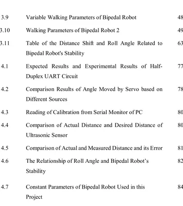
3.9 Variable Walking Parameters of Bipedal Robot 48
3.10 Walking Parameters of Bipedal Robot 2 49
3.11 Table of the Distance Shift and Roll Angle Related to Bipedal Robot's Stability
63
4.1 Expected Results and Experimental Results of Half-Duplex UART Circuit
77
4.2 Comparison Results of Angle Moved by Servo based on Different Sources
78
4.3 Reading of Calibration from Serial Monitor of PC 80 4.4 Comparison of Actual Distance and Desired Distance of
Ultrasonic Sensor
80
4.5 Comparison of Actual and Measured Distance and its Error 81 4.6 The Relationship of Roll Angle and Bipedal Robot’s
Stability
82
4.7 Constant Parameters of Bipedal Robot Used in this Project
[image:13.595.119.496.152.577.2]xiv
LIST OF FIGURES
FIGURE TITLE PAGE
2.1 Cart Table Model 7
2.2 Pictures of Three Controller Board in the Markets 13
2.3 Robotis Bioloid Premium Robot Kit 2 15
2.4 Kondo KHR-3HV R2 Humanoid Robot Kit 15
3.1 Overall Project Development Flow Chart 22
3.2 Process Flow Chart For Design and Construct Bipedal Robot
24
3.3 Arduino UNO 25
3.4 Arduino Mega 2560 27
3.5 Dynamixel AX-12A Servo 29
3.6 CM-5 Internal Half-Duplex UART Circuit 31
3.7 Schematic Diagram for SN74LS241N 32
3.8 Circuit Diagram of Half-duplex UART Circuit 33 3.9 Circuit Diagram for Half-Duplex UART for Dynamixel
AX-12A Servo
35
3.10 Experiment Setup for Half-Duplex UART for Dynamixel AX-12A Servo
36
3.11 Circuit diagram of the Arduino and Ultrasonic Ranging Module HC-SR04
38
xv
3.12 Experiment Setup of Ultrasonic Sensor with Arduino UNO 39
3.13 Bipedal Robot used in this Project 40
3.14 Arduino Mega and Half-duplex UART Circuit 41
3.15 Circuit diagram for the Arduino Mega and Half-duplex UART Circuit
41
3.16 Process Flow Chart of Walking Pattern Generation 42
3.17 Program Flow Chart 43
3.18 Kinematic Model of Simple Bipedal Robot 44
3.19 Walking Cycle of Bipedal Robot 45
3.20 Walking Parameters for Bipedal Robot 47
3.21 Position Graph of Left Leg from Time t=0 to t=T 49 3.22 Position Graph of Right Leg from Time t=0 to t=T 50
3.23 Graph of x-reference Point versus Time 50
3.24 Position Graph of Hip Joint and Ankle Joint versus Time 51
3.25 Trajectory Graph of Left Leg 52
3.26 Joint Parameters of Left Leg at t=0 53
3.27 Ankle Joint of Left Leg at t=0 54
3.28 Joint Parameter of Left Leg at t=T/2 55
3.29 Joint Parameters of Right Leg at t=0 57
xvi
3.31 Front View of Bipedal Robot (Double Support Phase) 59 3.32 Front view of Bipedal Robot (Single Support Phase) 60 3.33 Experiment Setup for Study the Relationship of Roll Angle and
its Stability
62
3.34 Side View of the Pedals of the Bipedal Robot During Walking 64 3.35 Top View of the Pedals of the Bipedal Robot During Walking 65
3.36 Turn Left Algorithm of Bipedal Robot 65
3.37 Turn Right Algorithm of Bipedal Robot 66
3.38 C++ Program is Getting Constant Parameters of Bipedal Robot 67 3.39 Joint Parameter Generated by the C++ Program 68 3.40 Explanation of Matrix Generated by C++ Program 68 3.41 Matrix for a Complete Walking Cycle for Bipedal Robot 69
3.42 Part of the Arduino Coding 1 70
3.43 Part of the Arduino Coding 2 71
3.44 Experiment Setup for Implementing Walking Algorithm 72 3.45 Process Flow Chart of Implementation of Obstacle Avoidance
System into Bipedal Robot
74
3.46 Experiment Setup for Experiment 6
3.47 Circuit Diagram for Complete System 76
xvii
4.2 Comparison of the Actual And Measured Distance of Ultrasonic Sensor
81
4.3 The Graph of Distance Shift versus Roll angle 83 4.4 Displacement Along Z-axis versus Stride Length 84 4.5 Angle Position for Hip’s Pitch Servo versus Stride Length 85 4.6 Angle Position for Knee's Pitch Servo versus Stride Length 85 4.7 Angle Position for Ankle's Pitch Servo versus Stride Length 86 4.8 Angle Position Ankle's Roll Servo versus Stride Length 86 4.9 Comparison of Calculated and Actual Angle for Hip Joint (Left
Leg)
88
4.10 Comparison of Calculated and Actual Angle for Hip Joint (Right Leg)
88
4.11 Comparison of Calculated and Actual Angle for Knee Joint (Left Leg)
89
4.12 Comparison of Calculated and Actual Angle for Knee Joint (Right Leg)
89
4.13 Comparison of Calculated and Actual Angle for Ankle Joint (Left Leg)
90
4.14 Comparison of Calculated and Actual Angle for Ankle Joint (Right Leg)
xviii
4.15 Comparison of Calculated and Actual Angle for Hip Joint (Left Leg) When Facing Obstacle
92
4.16 Comparison of Calculated and Actual Angle for Knee Joint (Left Leg) When Facing Obstacle
93
4.17 Comparison of Calculated and Actual Angle for Ankle Joint (Left Leg) When Facing Obstacle
xix
LIST OF APPENDICES
APPENDIX TITLE PAGE
A Gantt Chart for FYP 1 and FYP 2 100
B1 Arduino Program Experiment 1 101
B2 Arduino Program Experiment 2 101
B3 Arduino Program Experiment 3 102
B4 Arduino Program Experiment 4 103
B5 Arduino Program Experiment 5 104
B6 Arduino Program Experiment 6 106
C Generated Joint Parameters 108
D C++ Coding for Joint Parameters Generation 110
1
CHAPTER 1
INTRODUCTION
1.1 Motivation
Since the first humanoid robot was made in the seventies, the technology has developed extremely. The number of scientist and researchers study on the humanoid robot are increasing every year. Scientist and engineers around the world are attempting to design and develop different kinds of humanoid robot to meet certain applications and research purpose. Humanoid robots are now being involved in many aspects such as educational, industry and military.
2 to handling tools and equipment created for the human. Mobile robot is limited by its structure and not able to work in the environment created for human.
It is necessary to design and develop a human-body structure shape robot which able to handling human equipment to help in those disaster. Humanoid robots developed must capable of working in the environments adapted with humans, side by side with them to speed up of the time of operation or instead of them when the environment is no friendlier for human but robot. In addition, an organization "Centre for Robot-Assisted Search and Rescue" founded on 2001 serves as crisis response and research organization which focus on robot technology have participated in numerous incidents. It has the largest number of deployments of rescue robots in the world[2].
3 1.2 Problem Statement
Humanoid robot is designed to substitute human to carry out some critical tasks and reduce labor workforce. The designed robot must capable doing things that human can do. Locomotion (moving to one place to one place) is one of the things a normal human can do.
The greater challenge is design a walking algorithm for the bipedal robot. In terms of hardware used, microcontroller as the brain of the bipedal robot must be able to understand the walking algorithm and give signal for the robot to move. The other components such as the actuator connected all joints must very precise in order to walking just like human. All the components used must able to interface with the main controller. Extra circuitry may add to the system to connect and control all the components used.
One way to design the walking motion of the bipedal robot is using the forward and inverse kinematic method. The problem using the forward kinematic is that the bipedal robot consists of more than 6 servos, this may involve a calculation of a large matrix, the servo used is very precise with smaller resolution, a smaller angle change may have significant change on the matrix. Moreover, the bipedal robot is a moving body, it does not have a fixed base in a fixed position, hence, to move all the part of bipedal robot forward (walking) may involve a lot of calculation.
Inverse kinematic method to design the walking pattern is suitable for this project. The problem faced is how to deal with the angle change on every single moment. Joint parameters along the stride length of bipedal robot is needed to calculated to design a smooth walking pattern. Other method like code generation may use to generated all the joint parameters by feeding inputs and several constant parameter of the bipedal robot.
4 1.3 Objectives
There are few objectives that need to achieve by end of this project. The objectives of this project are stated as below.
1. To design and construct a simple bipedal robot with obstacle avoidance system. 2. To design and analyze the walking algorithm of the bipedal robot.
1.4 Scopes
The scope of the project is stated as below.
1. The bipedal robot is designed and constructed by using Arduino Mega (based on Atmega328P) as a microcontroller and Dynamixel AX12-A servo motor as actuator.
2. The bipedal robot is designed to walk in 3 dimensional motions which are walking forward, turning left and turning right.
3. The design of bipedal robot is simple and consists of 8 degree of freedom which capable of dexterous three dimensional motion.
4. The project covers the design and analysis of the walking algorithm of the bipedal robot which is included the normal walking cycle in a flat surface and in
environment with obstacle.
5. The bipedal robot is embedded with SR04 Ultrasonic Module for obstacle avoidance system. The system is implanted to give a feedback to microcontroller and thus choosing the suitable walking algorithm.
5
CHAPTER 2
LITERATURE REVIEW
2.1 Introduction to Bipedal Robot
The word "robot" was first introduced in 1921 by a Czech writer, according to Robotics Institute of America (RIA) [3], robot can be defined as:
" A re-programmable multi-functional manipulator designed to move materials, parts, tools, or specialized devices through variable programmed motions for the performance of a variety of task"
Robot is a mechatronic machine which is controlled by a controller equipped with electrical circuitry and mechanical parts to do any task programmed by human. There are many robots such as mobile robot, industrial robot and service robot. Certain robot such as industrial robot and service robot are programmed to work in a limited work space only, while mobile robot is one kind of robot which able to move around to any environment with powered actuator.