City, University of London Institutional Repository
Citation
:
Rane, S., Kovacevic, A., Stosic, N. and Kethidi, M. (2013). CFD grid generation
and analysis of screw compressor with variable geometry rotors. In: 8th International
Conference on Compressors and their Systems. (pp. 601-612). Cambridge: Woodhead
Publishing. ISBN 9781782421696
This is the published version of the paper.
This version of the publication may differ from the final published
version.
Permanent repository link:
http://openaccess.city.ac.uk/4417/
Link to published version
:
Copyright and reuse:
City Research Online aims to make research
outputs of City, University of London available to a wider audience.
Copyright and Moral Rights remain with the author(s) and/or copyright
holders. URLs from City Research Online may be freely distributed and
linked to.
City Research Online:
http://openaccess.city.ac.uk/
[email protected]
CFD grid generation and analysis of screw
compressor with variable geometry rotors
S Rane, A Kovacevic, N Stosic, M Kethidi
City University London,
Centre for Positive Displacement Compressor Technology, UK
ABSTRACT
This paper presents development of an algebraic grid generation algorithm applicable to Finite Volume Method for Computational Fluid Dynamics (CFD) calculation of variable pitch twin screw machines. It is based on the principles developed for the uniform pitch rotors with constant cross-section profile. The same algorithm could be also used for rotors with variable profile geometry. Performance predictions are obtained by ANSYS CFX for an oil-free 4/5 lobed twin screw compressor with variable pitch rotors and uniform ‘N’ profile. A comparison with the performance of a compressor of the same rotor size and wrap angle, but with the uniform pitch rotors showed that the variable pitch rotors give better compression characteristics. This is achieved by reduced throttling losses, reduced length of the sealing line towards the high pressure end and a larger discharge area for the same pressure ratio.
NOMENCLATURE
L – Rotor Length
D – Male Rotor Outer Diameter Φw – Male Rotor Wrap Angle
α
– Male rotor rotation angle Δα
– Increment in Male rotor angle Z – Axial distance along therotors
ΔZ – Increment in Axial distance ps – Starting Pitch
pe – Ending Pitch
z1 – Number of lobes on the Male
rotor
z2 – Number of lobes on the
Female rotor
i – Rotor Gear ratio = z2/z1
r.p.m – Male rotor speed
t – Time
Vi – Built in Volume Index
Abbreviations
CFD – Computational Fluid Dynamics FVM – Finite Volume Method SCORG© – Screw Compressor Rotor
Grid Generator
PDE – Partial Differential Equation TFI – Transfinite Interpolation GGI – Generalized Grid Interface
1 INTRODUCTION
obtained by grid generation techniques which start from the boundary representation and proceed to the interior. There are three main classes of mathematical techniques used for this process, a) Algebraic methods, b) Differential Methods and c) Variational methods. Authors such as (1), (9), (11), (12), (13), (14) and (15) have described different grid generation techniques in detail.
Figure 1. Oil injected Twin Screw compressor and its working chamber
Kovacevic et. al. in (5), (6), (7) and (8) have successfully used algebraic grid
generation method with boundary adaptation to generate numerical mesh for twin screw machines with constant pitch rotors. This has been implemented in the custom made program for the calculation of a screw compressor numerical mesh called SCORG©. The motivation for the present work was to extend the functionality
of SCORG© by including algorithms to handle twin screw rotors with variable pitch
[image:3.482.81.402.435.558.2]and variable section profiles. This would allow CFD simulations of these new types of machines (10). Numerical treatment of the uniform lead rotors and variable lead rotors differs mainly on grid generation. The axial distance between the grid points for constant pitch rotors is uniform. The challenge in generating a grid for variable lead rotors is that the axial distance and angular rotation of nodes change continuously. To accommodate this change, the grid needs variable axial spacing which still provides a conformal mesh. Figure 1 also shows the numerical grid in one of the cross-sections. For the variable pitch rotors this topology will remain the same over the length of the rotor but the relative position of the rotors will be different for the variable lead compared with the constant lead rotors. An additional challenge is that the grid generating procedure needs to accommodate large differences in length scales of the main domain and the clearances.
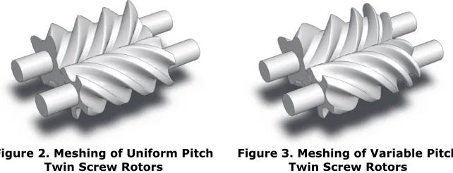
Figure 2. Meshing of Uniform Pitch
Twin Screw Rotors Figure 3. Meshing of Variable Pitch Twin Screw Rotors
The patent on variable pitch rotors by Gardner (3) dates back to 1969, but such machines are still rarely used due to the lack of efficient and economical manufacturing techniques. Figure 2 shows twin screw rotors with uniform pitch. Figure 3 shows the same size twin screw rotors with variable pitch. Gardner (3)
claims that for the same rotor lengths, diameters, wrap angles and lobe profiles, variable pitch rotors can achieve higher pressure ratios, larger discharge port area and reduce throttling losses when compared to constant pitch rotors.
As confirmed by many authors, efficiency of screw compressor depends upon the rotor profile, number of lobes, length, diameter and wrap angle of rotors and rotor clearances (2), (4) and (15). Based on these and the original work of Gardner (3) it is suggested that the effects of variable lead rotor designs are as follows:
a) If all other variables are unchanged for the constant lead rotors and variable lead rotors, the variable lead rotors will have shorter sealing line towards the shorter lead side which is normally discharge pressure side. Since the leakage loss is directly proportional to the length of the sealing line and the sealing line is shorter for the variable lead rotors in the high pressure regions, the leakage loss will be reduced. This may result in higher efficiencies with variable lead rotors.
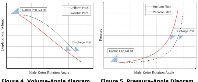
b) For variable lead rotors, the reduction of volume during the compression process will be faster than for constant lead rotors, as shown in Figure 4. Consequently the pressure will rise more rapidly for the variable lead rotors as shown in Figure 5.
[image:4.482.81.406.320.455.2]c) The built-in volume index is the ratio of the suction and discharge volumes. The suction volume is the maximum volume at which the suction port is usually closed and where the compression process begins. The discharge volume is the size of the compression chamber at the moment of opening of the discharge port. As shown in Figure 4, to achieve same volume index for variable pitch rotors the discharge port should be opened earlier which allows it to be bigger than in the constant lead case. Hence it is possible to have a greater discharge area at a similar pressure ratio and this will reduce the throttling losses.
Figure 4. Volume-Angle diagram Figure 5. Pressure-Angle Diagram
d) If the same size of discharge port is retained for both the variable and uniform lead rotors, the discharge pressure of the variable rotors will be higher. This indicates that variable lead rotors can achieve a higher Vi index.
2 GRID GENERATION FOR VARIABLE PITCH AND VARIABLE PROFILE SCREW ROTORS
[image:5.482.82.393.190.341.2]For the Uniform Pitch rotors, there is a fixed relation of the axial distance between the cross sections and the unit rotation angle over the entire length of the rotor. Grid generation in these cases is convenient because if the profile is constant, the grid generated for one interlobe space can be reused in consecutive interlobes. However, for rotors of variable pitch, this relation varies along the length of the rotor. Therefore it is impossible to use the same method with a constant axial distance between sections for grid generation of such rotors. At the same time the rotors need to rotate at a constant angular speed similar to the rotors of constant pitch. In such a case the angular and axial intervals for grid definition do not relate directly to the angular rotation. Figure 6 shows the grid difference between the constant and variable pitch rotors.
Figure 6. Axial spacing difference between uniform pitch and variable pitch rotor grids
In order to achieve this, the existing procedure used in SCORG© has been
reformulated to be adaptable with the variable pitch and variable profile screw rotors. The pitch variation could be constant, linear or stepped. The former is used in screw vacuum pump technology while the latter is applied in some car superchargers. The expressions can be specified in the form of equations 1 – 4.
Two approaches are proposed here to the solution of grid generation for the CFD analysis of such machines. Approach 1 is easier to implement by modifying the existing procedure and is suitable for variable pitch machines with a uniform rotor profile. Approach 2 is more complex in nature but is generally applicable for any cross section, including conical rotors.
2.1 Approach 1
In this approach, the pitch function is used to derive a relationship between the fixed angular increments Δα, from one section to the other and the required variable axial displacements ΔZ1, ΔZ2, ΔZ3…. ΔZn. By this means, the set of point
coordinates generated for one angle of rotation is simply re-positioned in the axial direction with variable ΔZ.
[image:6.482.76.412.237.352.2]A linear variation as in Equation 5 has been used to find the axial position of each of the sections over the rotor length in an example shown in Figure 7. Additional computational effort is required compared to the uniform pitch rotors to calculate this axial position for each cross section as the axial spacing and the rotation of the rotors are not in the direct relation to each other. The assembly of a grid from 2D cross sections to a 3D structure remains the same as for constant lead rotors. However, this approach cannot be used if there are any variations in the rotor profile along the rotor length.
Figure 7. Example of variable pitch grid with uniform profile: 5/6 ‘N’ rotors 2.2 Approach 2
This approach allows more generic generation of rotors with variable rotor pitch and variable cross section profile over the length of the rotor. Therefore, in addition to the variation of axial position of cross sections used in Approach 1, this algorithm needs to facilitate change of the rotor profile over the cross sections.
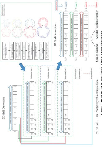
This grid generation algorithm is shown in a block diagram in Figure 8. The foundation of this approach is based on the assumption that every cross section contains a conjugate screw rotor pair. Therefore each cross section can be handled independently and the grid generation process which uses rack to divide working domain in two subdomains for the male and female rotors, can be repeated over each cross section independently.
2.2.1 Procedure
The process starts with the division of the rotor length into n number of cross sections and proceeds with the generation of 2D vertex data (Nodal x and y coordinates) in the first cross section. This involves boundary discretization and adaptation. Interior nodes at this section are calculated using TFI and the vertex data are recorded after grid orthogonalisation and smoothing operations. This step is labelled as ‘Subroutine Run – 1’ in the block diagram.
F
igu
re
8
. V
a
ri
able
Pit
ch
an
d V
a
ri
abl
e
Pr
ofi
le
G
rid
G
e
n
e
rat
[image:7.482.79.409.92.564.2]The 2D grid generation is repeated n times until all cross sections along the z axis are calculated. Calculated vertex coordinates are generated first for the initial time step and then the process is repeated for all required time steps. Blocks of vertices representing first rotor position in each cross section are
collected to construct the 3D assembly for the first time step. The particular attention is given to the correct z coordinate position of each cross section. This initial mesh is called Mesh-0. Consequently, the second mesh called Mesh-1 is constructed from the corresponding data for the second time step and the process is repeated until meshes for all required time steps are generated.
2.2.2 Example of application of approach 2
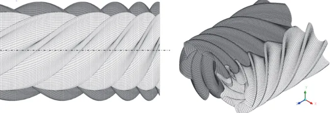
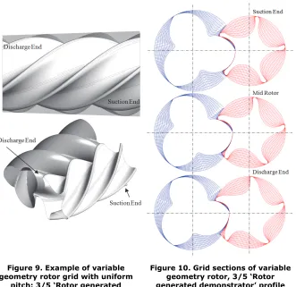
[image:8.482.76.407.248.569.2]An example of variable geometry rotor grid generated using approach 2 is shown in Figure 9. The rotor cross section profile changes continuously from the one to another end of the rotors. This set of rotors with parallel axis has a fixed centre distance so that the rotors are tapered. Namely, outer diameter of the main rotor is reducing from the suction to the discharge end while the inner diameter remains constant. On the gate rotor, the inner diameter is changing while the outer diameter is constant. Figure 10 shows the 2D cross sections grids for variable rotor “Rotor generated demonstrator” profile at the suction end, middle of the rotors and the discharge end.
Figure 9. Example of variable geometry rotor grid with uniform
pitch: 3/5 ‘Rotor generated demonstrator’ profile
3. CFD ANALYSIS
The validation of the new grid generation procedures is performed by use of numerical CFD analysis. Numerical mesh for all cases is generated by use of the updated SCORG© employing Approach 1 to generate all required cases. The
performance prediction of the variable lead screw compressor were obtained in order to evaluate
a. Indicator diagrams,
b. Increase in discharge port area for a given pressure ratio, c. Reduction in sealing line length towards the high pressure zones.
These characteristics are identified in the literature (3) as advantages of the variable lead rotors. Three cases were analysed, namely:
Case 1. Uniform Pitch rotors and a discharge port opening area to give a built in
volume index Vi of 1.8.
Case 2. Uniform Pitch rotors and a reduced discharge port opening area to give
built in volume index Vi > 1.8. In this case, the compression chamber is
exposed to the discharge pressure relatively late in the cycle as shown in Figure 14. This corresponds to an additional male rotor rotation of about 6.75° and allows for further pressure build up in the chambers.
Case 3. Variable Pitch rotors with the discharge port opening area equivalent to
[image:9.482.120.353.289.465.2]that of Case 1.
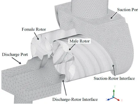
Figure 11. Different parts of the compressor numerical model
The configuration of the compressor is as follows; Rack generated ‘N’ profile, Male rotor with 4 lobes and a 60mm outer diameter, Gate rotor with 5 lobes, L/D ratio 1.55 and centre distance 42mm. The wrap angle on the male rotor was 306°. The compressor was run at 10000 rpm which gives a tip speed of 31.5m/s. The simulation was performed for oil free mode in order to avoid influence of oil on the process. Radial and interlobe clearances were set to 10µm. Axial end clearances were not included. The lead on the male rotor for the uniform pitch rotors was 108.8 mm. The variable lead male rotor had lead of 125.0 mm at the suction end, 108.8 mm in the middle of the rotors and 92.6mm at the discharge end. The wrap angle remains the same as for the uniform lead rotors. The rotor grids were generated with the same density in all three cases. The numerical grids for ports were generated externally using commercial grid generator. Figure 11 shows the
different parts of the numerical model. The compressor domain is decomposed into four main sub-domains, namely Male rotor flow domain, Female rotor flow domain, Suction port domain and Discharge Port domain. These domains are connected through sliding interface.
Constant pressure receivers were positioned at both ends using the procedure described in (6). The suction and discharge pipes were reasonably extended to obtain good convergence of the flow and reduce the numerical discrepancies arising from the pressure pulsations in the suction and discharge flows. The pressure in the suction receiver was set to 1.0bar while the Discharge receiver was set to 3.0bar. The convergence criteria for all equations were set to 1.0x10⁻³ and coefficient loops
for every time step was set at 10. During solution, r.m.s residuals for all time steps reached between 1.0x10⁻³ and 5.0x10⁻³ for momentum equation and below 1.0x10⁻³
for continuity and energy equations. The calculations were run sufficiently long such that a cyclic repetition of flow and pressure characteristics were identified at the boundaries. The working fluid was air following an ideal gas law with the molar mass of 28.96 kg kmol-1, Specific Heat Capacity 1004.4 J kg-1 K-1, Dynamic
Viscosity 1.831x10⁻⁵ kg m-1 s-1 and Thermal Conductivity 2.61x10⁻² W m-1 K-1.
3.1 Results and Discussion
3.1.1 Indicator diagram
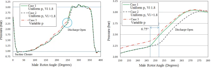
[image:10.482.73.412.351.464.2]Figure 12 shows the indicator diagram for three different cases. Case 3 with the variable rotor lead has a steeper rise in pressure than Case 1 and Case 2 which have constant rotor lead. At the same time Case 1, with the same discharge area as that in Case 3, builds up the least pressure before the compression chamber is exposed to the discharge pressure at about 246° male rotor rotation. Near this region, Case 2, with a reduced discharge port area, continues with the internal compression before it is exposed to the discharge pressure. This lag is about 6.75° of the male rotor rotation.
Figure 12. Absolute Pressure
variation with Male Rotation variation near discharge opening Figure 13. Absolute Pressure period of rotation
3.1.2 Discharge Port Area
Figure 14. Discharge Port Area gain with variable lead rotor for the same
delivery pressure
Figure 15. Mass Flow Rate at Suction and Discharge
Figure 15 shows the mass flow rate at the suction and discharge of the compressor. The average flow was found to be similar in all three cases. The dip in flow at the beginning of the cycle is due to under-compression in which case the discharge pressure is higher than the pressure reached in the compressor chambers just before the opening of the port. The highest dip in flow was obtained for Case 1 with uniform rotor pitch, which developed the least internal pressure (Figure 13).
3.1.3 Sealing Line Length
[image:11.482.72.420.47.193.2]The interlobe sealing line is the line of closest proximity between the two rotors. The leakage of gas takes place through this gap and is proportional to the length of the sealing line and clearance normal to it (2), (4) and (15). Contours of pressure distribution on the rotors can be established from numerical calculations and the dividing line between high and low pressure levels can be considered as the sealing line. The maximum pressure gradient is present across this division and is the driving force for leakages.
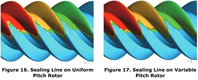
Figure 16. Sealing Line on Uniform
Pitch Rotor Figure 17. Sealing Line on Variable Pitch Rotor
Figure 16 shows the sealing line obtained on the uniform pitch rotors (Case 1 and
Case 2). Figure 17 shows the sealing line obtained on the variable pitch rotor (Case
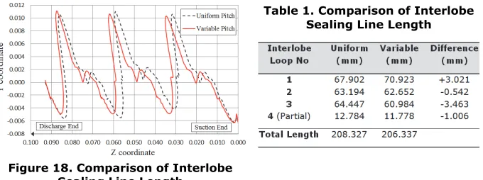
3). The projection of the sealing line on the rotor normal plane shows the difference more clearly in Figure 18. The sealing line on the uniform pitch rotor is of the same length for each interlobe space along the rotor. However, on the variable pitch rotors the sealing line is longer at the suction end and shorter at the discharge end of the rotor.
[image:11.482.72.409.372.508.2]Table 1 presents the variation in the sealing line lengths between the uniform and variable pitch cases at one of the rotor positions, and also gives the magnitude of the differences from the suction to the discharge ends of the rotors. At the suction end the sealing line on variable pitch rotor is 3mm longer but at the discharge end it is 3.5mm shorter. This helps to reduce leakage as the pressure difference across the sealing line is highest at the discharge end and smallest at the suction end. Also the total length was 2mm shorter.
4 CONCLUSION
3D CFD grid generation for twin screw compressors with variable pitch rotors was formulated and implemented successfully. The framework defined in this research is suitable for rotors with variable lead and variable profiles. Examples of grids are presented in the paper and CFD analysis was performed for the variable lead, constant profile rotors.
The analysis showed that by varying the rotor lead continuously from the suction to the discharge, it is possible to improve compression characteristics with a steeper internal pressure build up. The analysis also shows that varying the rotor lead allows a larger size of the discharge port area, thereby reducing throttling losses, and provides increase in volumetric efficiency by reducing the sealing line length in the high pressure zone. These latest enhancements in the grid generation open new opportunities for further investigation of the flow behaviour and performance predictions for variable lead and variable profile screw machines by the use of CFD.
REFERENCE LIST
(1) Eiseman PR, Hauser J, Thompson JF, Weatherill NP, Numerical Grid Generation in Computational Field Simulation and Related Fields, Proceedings of the 4th
International Conference, Pineridge Press, Swansea, Wales, UK, 1994.
(2) Fleming JS, Tang Y. The Analysis of Leakage in a Twin Screw Compressor and its Application to Performance Improvement, Proceedings of IMechE, Part E,
Journal of Process Mechanical Engineering, 1994; 209, 125.
(3) Gardner JW. US Patent No 3,424,373 – Variable Lead Compressor. Patented 1969.
[image:12.482.74.414.45.172.2](4) Hanjalic K, Stosic N. Development and Optimization of Screw machines with a simulation Model – Part II: Thermodynamic Performance Simulation and Design Optimization. ASME Transactions. Journal of Fluids Engineering. 1997; 119, 664.
Table 1. Comparison of Interlobe Sealing Line Length
(5) Kovacevic A, Stosic N, Smith IK. Grid Aspects of Screw Compressor Flow Calculations, Proceedings of the ASME Advanced Energy Systems Division, 2000; 40, 83.
(6) Kovacevic A. Three-Dimensional Numerical Analysis for Flow Prediction in Positive Displacement Screw Machines, Ph.D. Thesis, School of Engineering and Mathematical Sciences, City University London, UK, 2002.
(7) Kovacevic A. Boundary Adaptation in Grid Generation for CFD Analysis of Screw Compressors, Int. J. Numer. Methods Eng., 2005; 64, 3, 401-426.
(8) Kovacevic A, Stosic N, Smith IK. Screw compressors - Three dimensional
computational fluid dynamics and solid fluid interaction, ISBN 3-540-36302-5,
Springer-Verlag Berlin Heidelberg New York, 2007.
(9) Liseikin VD. Grid Generation Methods, ISBN 3-540-65686-3, Springer-Verlag (1999).
(10)Rane S, Kovacevic A, Stosic N, Kethidi M. Grid Deformation Strategies for CFD Analysis of Screw Compressors, Int Journal of Refrigeration, http://dx.doi.org /10.1016/j.ijrefrig.2013.04.008, 2013.
(11)Samareh AJ, Smith RE. A Practical Approach to Algebraic Grid Adaptation,
Computers & Mathematics with Applications, 1992; 24, 5/6, 69-81.
(12)Shih TIP, Bailey RT, Ngoyen HL, Roelke RJ. Algebraic Grid Generation For Complex Geometries, Int. J. Numer. Meth. Fluids, 1991; 13, 1-31.
(13)Soni BK, Grid Generation for Internal Flow Configurations, Computers &
Mathematics with Applications, 1992; 24, 5/6, 191-201.
(14)Steinthorsson E, Shih TIP, Roelke RJ. Enhancing Control of Grid Distribution In Algebraic Grid Generation, Int. J. Numer. Meth. Fluids, 1992; 15, 297-311. (15)Stosic N, Smith IK, Kovacevic A. Screw Compressors: Mathematical Modeling
and Performance Calculation, Springer Verlag, Berlin, ISBN: 3-540-24275-9,
2005.
(16)Thompson JF, Soni B, Weatherill NP. Handbook of Grid generation, CRC Press, 1999.