International Journal of Advanced Engineering, Management and Science (IJAEMS) Infogain Publication (Infogainpublication.com
www.ijaems.com
Preparing Generic Spiral Structure using
Optimized Design Parameters
Dheeraj Sharma,
Department of Electronics & Communication Engineering,
Abstract— In this paper, frequency reconfigurable spiral
patch antenna is designed. Frequency reconfiguration is achieved by changing the electrical length of antenna with the help of PIN diode switch. Design parameter
antenna are optimized to get improved results. After that, generic spiral structure is designed using these
values. This will reduce complexity and simulation time. Now, there is no need to redesign spiral structure for different values of design parameters. Just have to put values of parameter in their respective variable and this generic structure will be converted to desired structure. This will reduce design complexity and simulation time.
Keywords— FR4 Substrate, Rectangular Spiral Microstrip Antenna (RSMA), Coaxial feeding, PIN diode.
I. INTRODUCTION
Reconfigurable microstrip antenna plays a
wireless communication. Microstrip patch may have many conventional shapes example rectangular, circular, spiral [1]. Rectangular spiral structure consist thin spiral pattern printed on substrate and fed from the center. It has advantages like reduced size, low profile and high efficiency. These structures show characteristics of circularly polarization with moderate gain. It can have any number of turns. Spiral structures are broadly classified into two categories- Archimedean spiral and rectangular spiral. Spiral antennas are basically frequency independent antenna. Frequency independent antennas are antennas whose radiation pattern, impedance and polarization remain unchanged over wide bandwidth. Frequency pattern of such antennas depends only on physical dimensions. Spiral antenna’s radiation pattern direction is perpendicular to plane of spiral.
have wide half power beam width and it LAN, GSM, CDMA, RADAR applications
Thus, it can avoid use of different antenna for different services. Numerical analysis of spiral by moment method and this antenna can be mounted over ground plain to attain
International Journal of Advanced Engineering, Management and Science (IJAEMS) Infogainpublication.com)
Preparing Generic Spiral Structure using
Optimized Design Parameters
Dheeraj Sharma, Vinita Agrawal
Department of Electronics & Communication Engineering, Swami Keshvanand Institute of Technology, Management & Gramothan Jaipur, Rajasthan, India
frequency reconfigurable spiral Frequency reconfiguration is achieved by changing the electrical length of antenna with esign parameters of spiral improved results. After that, a using these optimized This will reduce complexity and simulation time. there is no need to redesign spiral structure for different values of design parameters. Just have to put values of parameter in their respective variable and this ll be converted to desired structure. This will reduce design complexity and simulation time.
FR4 Substrate, Rectangular Spiral Microstrip Antenna (RSMA), Coaxial feeding, PIN diode.
INTRODUCTION
Reconfigurable microstrip antenna plays a wider role in wireless communication. Microstrip patch may have many ectangular, circular, spiral etc Rectangular spiral structure consist thin spiral pattern printed on substrate and fed from the center. It has like reduced size, low profile and high efficiency. These structures show characteristics of circularly polarization with moderate gain. It can have any number of turns. Spiral structures are broadly classified into rectangular spiral. frequency independent Frequency independent antennas are those whose radiation pattern, impedance and polarization remain unchanged over wide bandwidth. depends only on its Spiral antenna’s radiation pattern direction is perpendicular to plane of spiral. These antennas have wide half power beam width and it can be used in LAN, GSM, CDMA, RADAR applications etc [2]-[4]. oid use of different antenna for different sis of spiral by moment method and this antenna can be mounted over ground plain to attain
bidirectional radiation and study of central loading to improve axial ratio[5]-[6].
Frequency Reconfigurability is the
change its resonant frequency by changing structure while radiation pattern and polarization remains unchanged. Its operating frequency can be
some length of the antenna any other means. The radiation length antenna possesses
because current distribution will remain same. Effective length of antenna
diodes, optical diodes or by mechanical methods. PIN diode switches are mostly used because they have advantages like fast switching speed, ease of handling capacity, resistance at RF frequency,
power consumption. Also, t on spiral structure.
II. THEORY AND DESIGN
The smallest and largest
defines their respective upper and lower cut Band theory defined working of spiral antenna as
in the region where the circumference of the spiral is equal to its wavelength [7]-[8] as shown in figure 1.
Fig. 1: Basic two wire rectangular spiral antenna
Where
r1: inner radius of spiral antenna r2: outer radius of spiral antenna W: width of spiral patch
[Vol-2, Issue-7, July- 2016] ) ISSN: 2454-1311
Page
|
1064
Preparing Generic Spiral Structure using
Optimized Design Parameters
Swami Keshvanand Institute of Technology, Management &
bidirectional radiation and study of central loading to
ency Reconfigurability is the property of antenna to resonant frequency by changing structure while pattern and polarization remains unchanged. Its operating frequency can be modified by adding or removing of the antenna through electrical, mechanical or any other means. The radiation pattern of this new modified same characteristics as first one because current distribution will remain same.
ength of antenna can be changed by MEMS, PIN or by mechanical methods. PIN diode re mostly used because they have advantages like ease of handling capacity, pure resistance at RF frequency, excellent isolation and less Also, this switch can easily be placed
THEORY AND DESIGN
The smallest and largest radius of the spiral structure their respective upper and lower cut-off frequencies. working of spiral antenna as operating in the region where the circumference of the spiral is equal
[8] as shown in figure 1.
Basic two wire rectangular spiral antenna
International Journal of Advanced Engineering, Management and Science (IJAEMS) Infogain Publication (Infogainpublication.com
www.ijaems.com
S: distance between turns
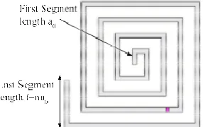
While designing spiral structure, spiral arm is increased b discrete steps in the manner a0, a0, 2a0,
4a0…….(M-1)a0, (M-1)a0 and Sa0 is designed as shown in figure 2 The value of a0 set as 0.503λ. The last turn length 4Ma0=C is taken as outer peripheral length of spiral antenna [9].
Fig. 2: Spiral patch configuration
Design parameters of spiral antenna are
width of the structure, length and width of the spiral segment and gap between two turns which are calculated below. The design frequency of this antenna
The operating wavelength of proposed structure is
λ = C/f = 120 mm (C= speed of light=
1. Thickness of Substrate
h= 0.134λ = 16.2 mm
2. Length of substrate
L=0.6λ = 70 mm
3. Width of spiral patch
w = 0.0135λ = 1.62 mm
4. First element length of spiral patch
a0 = 0.0503λ = 6.04 mm
5. Peripheral length of spiral patch
C = 4Ma0 = 1.61λ= 187 mm
We got length of the outermost spiral arm (C) is 187 mm which is within the range of 2λg < C < 3λ
and 216 mm). This ensures antenna radiates the circular polarization.
This spiral structure is placed on dielectric
further backed by conducting ground plane. FR4 material is selected as dielectric substrate
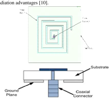
dielectric constant of 4.4. This dielectric substrate and ground plane both show same physical dimensions shape and same side length L which is 70 mm. Designed spiral patch antenna is excited wire feeding. Coax feed is applied at appropriate spiral structure. Coaxial connector is attach
surface of ground plane. Coaxial wire after passing through substrate is soldered to spiral patch as shown in figure 3.
International Journal of Advanced Engineering, Management and Science (IJAEMS) Infogainpublication.com)
spiral arm is increased by
2a0, 3a0, 3a0,4a0, is designed as shown in λ. The last turn length =C is taken as outer peripheral length of spiral antenna
Spiral patch configuration
height, length & length and width of the spiral s which are calculated antenna is 2.5 GHz.
The operating wavelength of proposed structure is
(C= speed of light=3×10⁸)
First element length of spiral patch
Peripheral length of spiral patch
length of the outermost spiral arm (C) is 187 mm g < C < 3λg (i.e. 144 mm ensures antenna radiates tilted beam of
is placed on dielectric material which is by conducting ground plane. FR4 type substrate which has ielectric substrate and show same physical dimensions square
70 mm.
is excited through coaxial appropriate location of attached to lower surface of ground plane. Coaxial wire after passing through patch as shown in figure 3.
Coaxial feeding is mostly used because of its
fabricate, good impedance matching and low spurious radiation advantages [10].
Fig. 3. Coaxial feeding of designed antenna
III. OPTIMIZATION OF THE DIFFERENT PARAMETERS
Effect of height of dielectric substrate and last segment length (l) of spiral patch on matching characteristics as well as radiation properties is analyzed. Variation of other parameter like the width of spiral is not discussed becaus has negligible effect on performance of antenna
A. Substrate height optimization (h)
The thickness of the substrate (H) is calculated 16 mm by using the relation (0.134
optimization the antenna geometry is analyzed for
values of H in multiple of 1.6 mm. Simulated return loss at both switch ON and OFF state for different substrate heights are given in figure 4
[Vol-2, Issue-7, July- 2016] ) ISSN: 2454-1311
Page
|
1065
Coaxial feeding is mostly used because of its ease to fabricate, good impedance matching and low spurious
Fig. 3. Coaxial feeding of designed antenna
OPTIMIZATION OF THE DIFFERENT PARAMETERS
Effect of height of dielectric substrate and last segment ) of spiral patch on matching characteristics as well as radiation properties is analyzed. Variation of other parameter like the width of spiral is not discussed because it has negligible effect on performance of antenna
Substrate height optimization (h)
The thickness of the substrate (H) is calculated 16 mm by ) from existing literature. For optimization the antenna geometry is analyzed for different values of H in multiple of 1.6 mm. Simulated return loss at both switch ON and OFF state for different substrate heights are given in figure 4.
International Journal of Advanced Engineering, Management and Science (IJAEMS) Infogain Publication (Infogainpublication.com
www.ijaems.com
(b)
Fig. 4. Return loss for different substrate heights (h) at (a) PIN ON state (b) PIN OFF s
Table.1: Return loss for different substrate heights (h) at pin on and off state
Parameter h=9.6 mm
h=11.2 mm
h=12.8 mm
PIN ON
PIN OFF
PIN ON
PIN OFF
PIN ON Resonant
frequency(f) (GHz)
2.27 2.7 2.23 2.63 2.18
Return loss at fr
(in dB) -19 -14 -41 -32 -27
From above figures and table, the optimize value of substrate height should be 11.2 mm. FR4 (Glass epoxy) materials of height 1.6 mm is used in seven stacked layers to maintain the height of 11.2 mm is selected as substrate.
B. Last segment length optimization (l)
The line segment length has important role in maintaining axial ratio at radiating frequency. This segment length is optimized for l=2a0 (12mm) to l=5a0
Segment lengths of designed spiral antenna are figure 5.
Fig. 5: Segment length representation of designed antenna
The value of last segment length (l) is obtained 24mm while designing four turn spiral antenna taking initial segment length 6 mm (a0=0.0134 ). Thickness of substrate is taken as 11.2 mm. Antenna is analyzed for nearby values of segment lengths (in multiple of a0=6 mm) to get best results
International Journal of Advanced Engineering, Management and Science (IJAEMS) Infogainpublication.com)
. Return loss for different substrate heights (h) at (a) PIN ON state (b) PIN OFF state
Return loss for different substrate heights (h) at
h=12.8 mm
h=16 mm
PIN PIN OFF
PIN ON
PIN OFF
2.18 2.57 2.11 2.1
-17 -10 -14
From above figures and table, the optimize value of substrate height should be 11.2 mm. FR4 (Glass epoxy) materials of height 1.6 mm is used in seven stacked layers to maintain the height of 11.2 mm is selected as substrate.
)
The line segment length has important role in maintaining axial ratio at radiating frequency. This segment length is
0 (30mm) length. Segment lengths of designed spiral antenna are shown in
Segment length representation of designed antenna
) is obtained 24mm while designing four turn spiral antenna taking initial segment ). Thickness of substrate is taken d for nearby values of =6 mm) to get best results
in terms axial ratio. Simulated axial ratio is given in f 6.
Fig. 6:Axial ratio for different segment length (l)
Table.2:Axial ratio for different segment lengths (
Parameters l=12
mm
Resonant
frequency (fr) (GHz)
2.24
Axial ratio at fr (in dB)
3.34
From above figure and table, it can be seen that lowest axial ratio (<3dB) is obtained for
at other length parameters will not result good circular polarization due to axial ratio>3dB.
IV. PREPARING GENERIC SPIRAL
Designing of spiral structure is difficult for every simulation for its every parametric variation. When we st
this structure in software (HFSS), it is quite difficult to place different size perpendicular segments. It is rigorous to remember the consecutive segments coordinate positions. This conventional process is time co
may have to change the dimensions many times. Therefore, variable based generic design is prepared which is used for further simulations.
The design parameters of generic s figure 7 below.
Fig. 7: Design properties of generic spiral structur
[Vol-2, Issue-7, July- 2016] ) ISSN: 2454-1311
Page
|
1066
in terms axial ratio. Simulated axial ratio is given in figure
Axial ratio for different segment length (l)
Axial ratio for different segment lengths (l)
=12 mm
l=18
mm
l=24
mm
l=30
mm
2.24 2.24 2.24 2.24
3.34 2.96 3.27 3.93
From above figure and table, it can be seen that lowest axial ratio (<3dB) is obtained for l=18mm at 2.24 GHz. Antenna at other length parameters will not result good circular polarization due to axial ratio>3dB.
PREPARING GENERIC SPIRAL STRUCTURE
Designing of spiral structure is difficult for every simulation for its every parametric variation. When we start modeling this structure in software (HFSS), it is quite difficult to place different size perpendicular segments. It is rigorous to remember the consecutive segments coordinate positions. This conventional process is time consuming as well. We to change the dimensions many times. Therefore, variable based generic design is prepared which is used for
The design parameters of generic structure are shown in
International Journal of Advanced Engineering, Management and Science (IJAEMS) [Vol-2, Issue-7, July- 2016] Infogain Publication (Infogainpublication.com) ISSN: 2454-1311
www.ijaems.com
Page
|
1067
Where
L, Ws and h: length, width and height of Substrate
wp, a0 and t: width, first segment length and thickness of Spiral structure
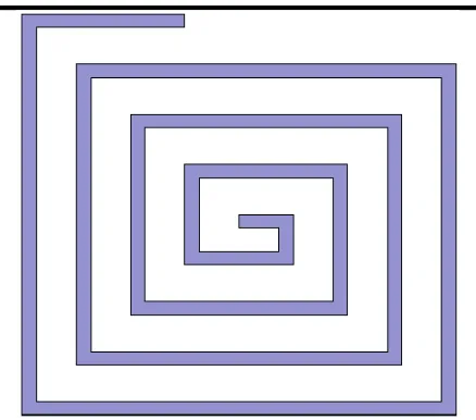
Coordinates and dimensions of all segments of spiral patch are expressed in terms of design parameters. Such preparing of generic structure is shown in figure 8 and explained below.
Fig. 8:Preparing generic spiral structure
Coordinates of point A: L/2, Ws/2, h Length of segment AB: a0
Coordinates of point B: L/2, Ws/2+a0-wp, h Length of segment BC: a0
Coordinates of point C: L/2+a0-wp, Ws/2+a0, h Length of segment CD: 2a0
Coordinates of point D: L/2+a0, Ws/2-a0, h Length of segment DE: 2a0
Coordinates of point E: L/2-a0, L/2-a0, h Length of segment EF: 3a0
Coordinates of point F: L/2-a0, Ws/2+2*a0-wp, h And so on……..
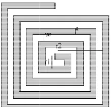
Prepared generic spiral structure using design parameters which are calculated for 5 GHz and 1 GHz is shown in figure 9 and 10 below.
Fig. 9:Small generic spiral structure radiating at 5 GHz
Fig. 10:Large generic spiral structure radiating at 1 GHz
V. CONCLUSION
Rectangular spiral microstrip antenna is designed and it is placed on FR4 substrate which is backed by conducting ground plane along with coax feeding. Different design parameters of antenna are optimized and optimized values of substrate height and last segment length obtained are 112 mm and 18 mm respectively. A universal spiral structure is prepared to avoid designing of spiral structure again and again for different design parameters and thus reducing simulation time and complexity.
REFERENCES
[1] G. C. Christodoulou, Y. Tawk, A. Youssef, A. S. Lane, and R. S. Scott, “Reconfigurable antennas for wireless and space applications,” Proceedings of the IEEE, vol. 100, no. 7, pp. 2250–2261, November 2012.
[2] C. A. Balanis “Antenna Theory Analysis and Design”, 3rd edition. New York: Wiley-Interscience, 2005, pp. 698–699.
[3] M. F. Abdul Khalid, M. A. Haron, A. Baharuddin, and A. A. Sulaiman, “Design of a spiral antenna for Wi-Fi application”, IEEE Inter. RF and Microwave Conf.
Proc., K.Lumpur, vol. 2-4, pp. 428–432, 2008
[4] U. Saynak and A. Kustepeli, “Novel square spiral antennas for broadband applications”, Frequenz, vol. 63, no. 1-2, p. 14, 2009
[5] Huifen Huang and Zonglin Lv, “A New Spiral Antenna with Improved Axial Ratio and Shorted Arm Length,”
Progress In Electromagnetic Research, Vol. 46, pp.
83-89, January, 2014.
International Journal of Advanced Engineering, Management and Science (IJAEMS) [Vol-2, Issue-7, July- 2016] Infogain Publication (Infogainpublication.com) ISSN: 2454-1311
www.ijaems.com
Page
|
1068
dielectric substrate,” IEEE Transactions on Antennas
and Propagation, Vol.5, pp.362 - 369, 2002.
[7] R. Bawer and J. J. Wolfe, “The spiral antenna,” IRE
Int. Convention Record, pt. T., pp. 84–95, 1960.
[8] J. Ely, C. Christodoulou, and D. Shively, “Square spiral microstrip antennas: Analysis for different sizes and substrate parameters using a personal computer,” in
Proc. IEEE Microwave Systems Conf., pp. 362–367,
Mar. 1995.
[9] H. Nakano, K. Nogami, S. Arai, H. Mimaki, and J. Yamauchi, “A spiral antenna backed by a conducting plane reflector”, IEEE Transactions on Antennas and
Propagation, vol. 34, no. 6, pp. 791–796, 1986.
[10] Karim Louertani, Regis Guinvarch, Nicolas Ribiere Tharaud and Marc Helier “External and coplanar feeding for spiral antenna,” In Proceeding IEEE
Antennas and Propagation society, international