Area and Power Efficient Booth’s Multipliers
Based on Non Redundant Radix-4
Signed-Digit Encoding
S.Reshma 1, K.Rjendra Prasad 2
P.G Student, Department of Electronics and Communication Engineering, Mallareddy Engineering College
Hyderabad, Telangana, India
Assistant Professor, Department of Electronics and Communication Engineering, Mallareddy Engineering College
Hyderabad, Telangana, India
ABSTRACT: In this paper, we introduce an architecture of pre-encoded multipliers for Digital Signal Processing
applications based on off-line encoding of coefficients. To this extend, the Non-Redundant radix-4 Signed-Digit (NR4SD) encoding technique, which uses the digit values {-1, 0, +1, +2} or {-2,-1,0,+1}, is proposed leading to a multiplier design with less complex partial products implementation. Extensive experimental analysis verifies that the proposed pre-encoded NR4SD multipliers, including the coefficients memory, are more area and power efficient than the conventional Modified Booth scheme.
KEYWORDS: Multiplying circuits, Modified Booth encoding, Pre-Encoded multipliers, VLSI implementation.
I. INTRODUCTION
MULTIMEDIA and Digital Signal Processing (DSP) applications (e.g., Fast Fourier Transform (FFT), audio/video CoDecs) carry out a large number of multiplications with coefficients that do not change during the execution of the application. Since the multiplier is a basic component for implementing computationally intensive applications, its architecture seriously affects their performance.
Constant coefficients can be encoded to contain the least non-zero digits using the Canonic Signed Digit (CSD) representation [1]. CSD multipliers comprise the fewest non-zero partial products, which in turn decreases their switching activity. However, the CSD encoding involves serious limitations. Folding technique [2], which reduces silicon area by time multiplexing many operations into single functional
units, e.g., adders, multipliers, is not feasible as the CSD-based multipliers are hard-wired to specific coefficients. In [3], a CSD-based programmable multiplier design was proposed for groups of pre-determined coefficients that share certain features. The size of ROM used to store the groups of coefficients is significantly reduced as well as the area and power consumption of the circuit. However, this multiplier design lacks flexibility since the partial products generation unit is designed specifically for a group of coefficients and cannot be reused for another group. Also, this method cannot be easily extended to large groups of pre-determined coefficients attaining at the same time high efficiency.
Modified Booth (MB) encoding tackles the aforementioned limitations and reduces to half the number of partial products resulting to reduced area, critical delay and power consumption. However, a dedicated encoding circuit is required and the partial products generation is more complex. Kim et al. proposed a technique similar to [3], for designing efficient MB multipliers for groups of pre-determined coefficients with the same limitations described in the previous paragraph.
II. MODIFIED BOOTH ALGORITHM
ISSN(Online) : 2319-8753 ISSN (Print) : 2347-6710
I
nternational
J
ournal of
I
nnovative
R
esearch in
S
cience,
E
ngineering and
T
echnology
(An ISO 3297: 2007 Certified Organization)
Vol. 5, Issue 9, September 2016
to the pre-encoded MB multiplier in which the encoded coefficients need 3 bits per digit, the proposed NR4SD scheme reduces the memory size. Also, compared to the MB form, which uses five digit values{-2,-1,0,+1,+2}, proposed NR4SD encoding uses four digit values. Thus, the NR4SD-based pre-encoded multipliers include a less complex partial products generation circuit. We explore the efficiency of the aforementioned pre-encoded multipliers taking into account the size of the coefficients’ ROM.
Modified Booth (MB) is a redundant radix-4 encoding technique [6], [7]. Considering the multiplication of the 2’s complement numbers A, B, each one consisting of n=2k bits, B can be represented in MB form as
-(1)
-(2)
where b−1 = 0. Each MB digit is represented by the bits s, one and two (Table 1). The bit s shows if the digit is negative (s=1) or positive (s=0). One shows if the absolute value of a digit equals 1 (one=1) or not (one=0). Two shows if the absolute value of a digit equals 2 (two=1) or not (two=0). Using these bits, we calculate the MB digits MB bj as follows:
-(3)
Equation (4)from the mb encoding signals
-(4)
Table 1.modified booth encoding table
III. NON REDUNDANT SIGNED DIGIT ENCODING
Fig.1 Block Diagram of the NR4SD- Encoding Scheme at the (a) Digit and (b) Word Level.
Fig.2 Block Diagram of the NR4SD+ Encoding Scheme at the (a) Digit and (b) Word Level.
NRS4D- algorithm
Step 1: Consider the initial values j = 0 and c0=0.
Step 2: Calculate the carry c2j+1 and the sum n+ 2j of a Half Adder (HA) with inputs b2j and c2j (Fig. 1a).
Step 3: Calculate the positively signed carry c2j+2 (+) and the negatively signed sum n 2j+1 (-) of a Half Adder* (HA*) with inputs b2j+1 (+) and c2j+1 (+) The outputs c2j+2 and n 2j+1 of the HA* relate to its inputs as follows
Step 4: Calculate the value of the bNR j digit.
-(5)
Equation (5) results from the fact that n2j+1 is negatively signed and n2j+ is positively signed. Step 5: j := j + 1.
Step 6: If (j < k 1), go to Step 2. If (j = k 1), encode the most significant digit based on the MB algorithm and considering the three consecutive bits to be b2k-1, b2k-2 and c2k-2 (Fig. 1b). If (j = k), stop.
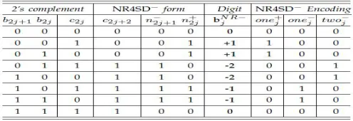
Table 2 shows how the NR4SD- digits are formed. Equations (6) show how the NR4SD- encoding signals.
ISSN(Online) : 2319-8753 ISSN (Print) : 2347-6710
I
nternational
J
ournal of
I
nnovative
R
esearch in
S
cience,
E
ngineering and
T
echnology
(An ISO 3297: 2007 Certified Organization)
Vol. 5, Issue 9, September 2016
-(6)
We observe that the NR4SD form has larger dynamic range than the 2’s complement form. NRS4D+ encoding
Step 1: Consider the initial values j = 0 and c0=0.
Step 2: Calculate the carry c2j+1 and the sum n+ 2j of a Half Adder (HA) with inputs b2j and c2j (Fig. 2a).
Step 3: Calculate the positively signed carry c2j+2 (+) and the negatively signed sum n 2j+1 (-) of a Half Adder* (HA*) with inputs b2j+1 (+) and c2j+1 (+)
The outputs c2j+2 and n 2j+1 of the HA* relate to its inputs as follows
Step 4: Calculate the value of the bNR j digit.
-(7) Equation (7) results from the fact that n2j+1 is negatively
signed and n2j+ is positively signed. Step 5: j := j + 1.
Step 6: If (j < k 1), go to Step 2. If (j = k 1), encode the most significant digit based on the MB algorithm and considering the three consecutive bits to be b2k-1, b2k-2 and c2k-2 (Fig. 1b). If (j = k), stop.
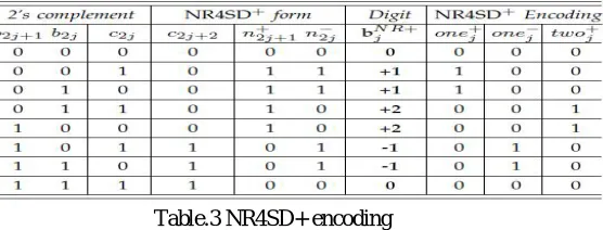
Table 3 shows how the NR4SD+ digits are formed. Equations (8) show how the NR4SD+ encoding signals.
Table.3 NR4SD+ encoding
As observed in the NR4SD- encoding technique, the NR4SD+ form has larger dynamic range than the 2’s complement form.
Considering the 8-bit 2’s complement number N, Table 4 exposes the limit values and two typical values of N, and presents the MB, NR4SD- and NR4SD+ digits that result when applying the corresponding encoding techniques to each value of N we considered. We added a bar above the negatively signed digits in order to distinguish them from the positively signed ones.
Fig3.system architecture of mb multiplier.
IV. PRE-ENCODED MB MULTIPLIER DESIGN
In this section, we explore the implementation of pre-encoded multipliers. One of the two inputs of these multipliers is pre-encoded either in MB or in NR4SD / NR4SD+ representation. We consider that this input comes from a set of fixed coefficients (e.g. the coefficients for a number of filters in which this multiplier will be used in a dedicated system or
the sine table required in an FFT implementation). The coefficients are encoded off-line based on MB or NR4SD algorithms and the resulting bits of encoding are stored in a ROM. Since our purpose is to estimate the efficiency of the proposed multipliers, we first present a review of the conventional MB multiplier in order to compare it with the pre-encoded schemes.
Fig.4the ROM of Pre-Encoded multipliers with standard coefficients in MB form.
In the pre-encoded MB multiplier scheme, the coefficient B is encoded off-line according to the conventional MB form (Table 1). The resulting encoding signals of B are stored in a ROM. The circled part of Fig. 3, which contains the ROM with coefficients in 2’s complement form and the MB encoding circuit, is now totally replaced by the ROM of Fig. 4. The MB encoding blocks of Fig. 3 are omitted. The new ROM of Fig. 5 is used to store the encoding signals of B and feed them into the partial product generators (PPj Generators - PPG) on each clock cycle. Targeting to decrease switching activity, the value ’1’ of sj in the last entry of Table 1 is replaced by ’0’. The sign sj is now given by the relation
sj = b2j+1 _ (b2j+1 ^ b2j ^ b2j 1):
ISSN(Online) : 2319-8753 ISSN (Print) : 2347-6710
I
nternational
J
ournal of
I
nnovative
R
esearch in
S
cience,
E
ngineering and
T
echnology
(An ISO 3297: 2007 Certified Organization)
Vol. 5, Issue 9, September 2016
Fig.5generation of ppj for conventional and pre-encoded mb multiplier.
Fig.6generation of ppj for NR4SD- and NR4SD+ multiplier.
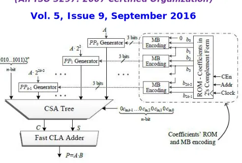
Pre-Encoded NR4SD Multipliers Design
The system architecture for the pre-encoded NR4SD multipliers is presented in Fig. 6. Two bits are now stored in ROM: n2j+1, n+2j (Table 2) for the NR4SD or n+ 2j+1, n 2j (Table 3) for the NR4SD+ form. In this way, we reduce the memory requirement to n+1bits per coefficient while the corresponding memory required for the pre-encoded MB scheme is 3n/2 bits per coefficient. Thus, the amount of stored bits is equal to that of the conventional MB design, except for the most significant digit that needs an extra bit as it is MB encoded. Compared to the pre-encoded MB multiplier, where the MB encoding blocks are omitted, the pre-encoded NR4SD multipliers need extra hardware to generate the signals of (6) and (8) for the NR4SD- and NR4SD+ form, respectively. The NR4SD encoding blocks of Fig. 6 implement the circuitry of Fig. 7. Each partial product of the pre-encoded NR4SD- and NR4SD+ multipliers is implemented based on Fig. 4c and 4d, respectively, except for the PPk1 that corresponds to the most significant digit. As this digit is in MB form, we use the PPG of Fig. 4b applying the change mentioned in Section 4.2 for the sj bit. The partial products, properly weighted, and the correction term (COR) of (11) are fed into a CSA tree. The input carry cin;j of (11) is calculated as cin;j = twoj_one j and cin;j = onej for the NR4SD- and NR4SD+ pre-encoded multipliers, respectively, based on Tables 2 and 3. The carry-save output of the CSA tree is finally summed using a fast CLA added.
Fig.7 system architecture of NR4SD encoding.
Fig.8 Extra Circuit Needed in the NR4SD Multipliers to Complete the (a) NR4SD and (b) NR4SD+ Encoding.
V. IMPLEMENTATION RESULTS
ise to synthesize the evaluated designs, considering the highest optimization degree and keeping the hierarchy of the designs.
Table 4.multiplier design
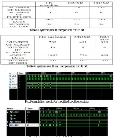
The below table 5 and table 6 are the synthasis results for the modified booth and non-redundant sign digit encoding minus and non redundant sign digit encoding plus for 16 and 32 bits respectively.
Table 5.syntasis result comparison for 16 bit.
Table 6 syntasis result and comparision for 32 bit.
Fig.9 simulation result for modified booth encoding.
ISSN(Online) : 2319-8753 ISSN (Print) : 2347-6710
I
nternational
J
ournal of
I
nnovative
R
esearch in
S
cience,
E
ngineering and
T
echnology
(An ISO 3297: 2007 Certified Organization)
Vol. 5, Issue 9, September 2016
Fig9,fig10,fig11 shows the simulation result for multiplier based on modified booth encoding and non redundant signed digit encoding minus and non redundant signed digit encoding plus respectively.
Fig.11 simulation result for NRS4D+encoding.
VI. CONCLUSION
In this paper, new designs of pre-encoded multipliers are explored by off-line encoding the standard coefficients and storing them in system memory .We propose encoding these coefficients in the Non-Redundant radix-4 Signed-Digit (NR4SD) form .The proposed pre-encoded NR4SD multiplier designs are more area and power efficient compared to the conventional and encoded MB designs. Extensive experimental analysis verifies the gains of the proposed pre-encoded NR4SD multipliers in terms of area complexity and power consumption compared to the conventional MB multiplier.
REFERENCES
[1] G. W. Reitwiesner, “Binary arithmetic,” Advances in Computers, vol. 1, pp. 231–308, 1960.
[2] K. K. Parhi, VLSI Digital Signal Processing Systems: Design and Implementation. John Wiley & Sons, 2007. [3] K. Yong-Eun, C. Kyung-Ju, J.-G. Chung, and X. Huang, “Csdbased programmable multiplier design for predetermined coefficient groups,” IEICE Trans. Fundam. Electron. Commun. Comput. Sci., vol. 93, no. 1, pp. 324–326, 2010.
[4] O. Macsorley, “High-speed arithmetic in binary computers,” Proc. IRE, vol. 49, no. 1, pp. 67–91, Jan. 1961.
[5] W.-C. Yeh and C.-W. Jen, “High-speed booth encoded parallel multiplier design,” IEEE Trans. Comput., vol. 49, no. 7, pp. 692– 701, Jul. 2000. [6] Z. Huang, “High-level optimization techniques for low-power multiplier design,” Ph.D. dissertation, Department of Computer Science, University of California, Los Angeles, CA, 2003.
[7] Z. Huang and M. Ercegovac, “High-performance low-power left-to-right array multiplier design,” IEEE Trans. Comput., vol. 54, no. 3, pp. 272– 283, Mar. 2005.