R E S E A R C H
Open Access
Performance limits of conventional and widely
linear DFT-precoded-OFDM receivers in
wideband frequency-selective channels
Kiran Kuchi
Abstract
This paper describes the limiting behavior of linear and decision feedback equalizers (DFEs) in single/multiple antenna systems employing real/complex-valued modulation alphabets. The wideband frequency-selective channel is modeled using a Rayleigh fading channel model with infinite number of time domain channel taps. Using this model, we show that the considered equalizers offer a fixed post detection signal-to-noise ratio (post-SNR) at the equalizer output that is close to the matched filter bound (MFB). General expressions for the post-SNR are obtained for zero-forcing (ZF)-based conventional receivers as well as for the case of receivers employing widely linear (WL) processing. Simulation is used to study the bit error rate (BER) performance of both minimum-mean-square-error (MMSE) and ZF-based receivers. Results show that the considered receivers advantageously exploit the rich
frequency-selective channel to mitigate both fading and inter-symbol interference (ISI) while offering a performance comparable to the MFB.
1 Introduction
Linear and decision feedback equalizers (DFEs) have been widely studied for the past 50 years. With the introduction of discrete Fourier transform-precoded-orthogonal frequency-division multiple access (DFT-precoded-OFDMA) [1,2] in the uplink of the long-term evolution (LTE) standard [3], there has been renewed interest in the design and analysis of these two receivers operating in wideband frequency-selective channels. DFT-precoded-OFDM, also known as single-carrier FDMA (SC-FDMA), is a variant of OFDM in which the modulation data is precoded using the DFT before mapping the data on the subcarriers. The resultant modulation signal exhibits low peak-to-average power ratio (PAPR). As the frequency-selective channel introduces inter-symbol interference (ISI), this method requires sophisticated channel equalization at the receiver.
In broadband wireless systems employing high band-widths, the propagation channel typically exhibits high frequency selectivity. For these systems, link performance measures such as the diversity order and bit error rate
Correspondence: [email protected]
Indian Institute of Technology Hyderabad, Hyderabad, India
(BER) of a conventional minimum mean-square error (MMSE)-based linear equalizers have not yet been fully characterized [4-9]. The noise enhancement phenomenon which is inherent in linear equalizers poses a difficulty in analyzing the receiver performance. The minimum mean-square error decision feedback equalizer (MMSE-DFE) [10,11], on the other hand, is an optimum canoni-cal receiver for channels with ISI. In frequency-selective channels, it provides full diversity, and the performance is generally comparable to the optimum matched fil-ter bound (MFB) [12]. Most of the prior works related to linear and decision feedback equalizers discuss the diversity order of the equalizers and do not quan-tify the exact performance of the equalizer. In many cases, simulation is typically used to determine the link performance.
The performance loss caused by the decision feedback section of the MMSE-DFE can be minimized by using a receiver structure that uses the MMSE-DFE feed-forward filter (FFF) as a pre-filter [13] which provides a minimum phase response followed by a reduced state sequence estimation (RSSE) [14] algorithm that uses set partition-ing and state dependent decision feedback principles. Note that the maximum likelihood sequence estimator (MLSE) [15,16] can be viewed as a special case of RSSE.
In typical channels, RSSE with an appropriately chosen number of states performs close to MLSE [17]. In spite of the availability of a number of alternatives to MLSE, linear and decision feedback equalizers are generally pre-ferred in wideband systems due to low implementation complexity.
In DFT-precoded-OFDM systems, the MMSE-DFE [18-20] equalizer can be implemented efficiently using a frequency domain FFF followed by a time domain DFE [21-31]. Computation of FFF and feedback filters (FBF) for DFT-precoded-OFDM differs from conventional single-carrier methods. Since DFT-precoded-OFDM permits frequency domain equalization, it simplifies the computa-tional requirements of both filter calculation and imple-mentation. In [32], an iterative block DFE method is proposed. This method uses a linear equalizer in the first iteration and applies block-level soft decision feedback in subsequent iterations. In this paper, we are mainly con-cerned with the analysis of conventional DFEs based on hard decision feedback.
For real-valued data transmission (e.g., binary phase-shift keying (BPSK) or amplitude-phase-shift keying (ASK)), widely linear (WL) equalizers which jointly filter the received signal and its complex-conjugate [33] are known to outperform conventional receivers. This concept has been applied for numerous wireless applications [34-43] including equalization, interference suppression, multi-user detection, etc. Implementation WL equalizers is dis-cussed in [39] for conventional time domain single-carrier systems. WL receiver algorithms are widely employed in global system for mobile communication (GSM) for (a) low-complexity equalization of binary Gaussian minimum shift keying (GMSK) modulation in frequency-selective channels (b) co-channel interference suppression using a single-receiver antenna. The latter feature is popularly known as single antenna interference cancelation (SAIC) [43,44].
Throughout this paper, we assume that the receiver has multiple spatially separated antennas. However, the anal-ysis, and the results of this paper hold for the case of single antenna as well. We consider a channel withvtime domain taps where the individual taps are modeled as independent and identically distributed (i.i.d.) complex Gaussian random variables with zero mean with per tap variance of 1v. The post-processing signal-to-noise power ratio (post-SNR) of the considered equalizers is analyzed in the limiting case asv → ∞. Using this model, Kuchi [45] has shown that the SNR at the output of a multi-antenna zero-forcing linear equalizer (ZF-LE) with Nr
antennas reaches a mean value ofNr−1 σ2
n , whereσ 2
ndenotes
the noise variance andNr > 1. For the case of the
single-receiver antenna, both ZF-LE and MMSE-LE are shown to perform poorly. Therefore, it is worthwhile to consider the DFE as an implementation alternative.
In this paper, we further generalize the results of [45] and analyze the limiting performance of three receiver algorithms, namely (a) conventional DFE, (b) WL ZF-LE and (c) WL ZF-DFE. While ZF-based methods per-mit analytical evaluation of the post-SNR of the receiver, simulation is used to study the performance of MMSE-based receivers. The post-SNR bounds developed in this paper provide new insights into the receiver performance. Specifically, we show that, in i.i.d. fading channels with infinitely high frequency selectivity, the post-SNR at the output of all the considered receivers reach a fixed SNR. Using these results, we quantify the performance gap of a given receiver with respect to the MFB. In contrast to the previous works where the focus is restricted to diver-sity analysis, the results of this paper provide a framework to analyze the link performance in channels with high frequency selectivity.
We would like to remark here that in multi-user OFDMA systems, impairments such as frequency off-sets, I/Q imbalance, and channel time variations affect the orthogonality of subcarriers and give rise to multi-user interference. Sophisticated equalization techniques are proposed in [46-49] to combat these impairments. In this paper, we restrict our attention to performance analysis in the presence of frequency-selective channels without considering any of the aforementioned impairments.
The organization of the paper is as follows: In section 3, we first generalize the finite-length ZF/MMSE-DFE results to the infinite-length case. Then, we obtain a gen-eral expression for the post-SNR of a ZF-DFE for the case of infinite length i.i.d. fading channel under the assumption of error-free decision feedback (ideal DFE). In section 4, we present the limiting analysis for receivers employing WL processing. Collection of complex and complex-conjugated copies of the received signal effec-tively doubles the number of receiver branches. We show that these additional signal copies obtained through WL processing helps the receiver to obtain a substantially higher post-SNR compared to conventional LEs. Analo-gous to the case of conventional ZF-DFE, in section 5, we obtain filter settings for the WL ZF/MMSE-DFE receiver. Then a general expression for the post-SNR of the WL ZF-DFE is obtained for the case of infinite-length i.i.d. fad-ing channel. In section 6, we present simulation results. Finally, conclusions are drawn in section 7.
Notation The following notation is adopted throughout the paper. Vectors are denoted using bold-face lower-case letters, matrices are denoted using boldface upper-case letters. Time domain quantities are denoted using the subscript t. The M-point DFT of a vector ht(l)
is defined as h(k) = M−1l=0 ht(l)e
−j2πkl
ht(l)= M1 M−1k=0 h(k)e j2πkl
M . The squared Euclidean norm of a row/column vectorh(k) = [h1(k),h2(k), ..,hn(k)] is
denoted as||h(k)||2 = nm=1|hm(k)|2. The circular
con-volution between two lengthN sequences is defined as x1(n)x2(n)=n=0N−1x1(n)x2((m−n))N where the
sub-script inx2((m−n))N denotes moduloNoperation and denotes circular convolution operation. The symbols
†,∗,Trdenote Hermitian, complex-conjugate and trans-pose operations, respectively andE[.] denotes expectation operator.
2 System model
The DFT-precoded-OFDMA transmitter sends a block of M i.i.d. real/complex-valued modulation alphabets with zero-mean and variance σ2
x. The DFT precoding of the
data streamxt(l)is accomplished using aM-point DFT as
x(k)= M−1
l=0 xt(l)e
−j2πlk
M , k=0, ..,M−1 (1)
where l and k denote the discrete time and subcarrier indices, respectively. Throughout this paper, we consider a wideband allocation. Therefore, the precoded data is mapped to all the availableMcontiguous subcarriers. The time domain baseband signal s(t) is obtained using an inverse discrete time Fourier transform (IDTFT)
s(t)= 1 M
M−1
k=0
x(k)ej2πkf(t−TCP), t∈[0,T+TCP]
(2)
whereT is the useful portion of OFDMA symbol,TCPis
the duration of the cyclic prefix (CP) andf = T1 is the subcarrier spacing.
3 MMSE-DFE receiver
The receiver front end operations such as sampling, syn-chronization, CP removal and channel estimation oper-ations are similar to a conventional system. Further, the memory introduced by the propagation channel is assumed to be less than that of the CP duration. Through-out this paper, ideal knowledge of channel state informa-tion is assumed at the receiver. We consider a receiver equipped withNrantennas. Stacking up the time domain
sample outputs of multiple-receiver antennas in a column vector format, we get
yt(l)=st(l)ht(l)+nt(l), l=0, 1, ..,M−1 (3)
where
yt(l) = yt,1(l), ..,yt,Nr(l)Tr, ht(l)=ht,1(l), ..,ht,Nr(l)Tr, nt(l) =
nt,1(l), ..,nt,Nr(l) Tr
denote the received signal, channel, and noise vectors of sizeNr×1. Here,st(l) corresponds to the sampled
ver-sion of the analog signals(t). The noise vector nt(l) is
composed of Nr i.i.d. complex-Gaussian noise random
variables each with zero-mean and varianceσn2
2 per
dimen-sion. Note that ht(n) is assumed to be a time-limited
channel vector where each element ofht(n)has a duration vsamples andM>>v. Taking theM-point DFT ofyt(l),
we get
y(k)=h(k)x(k)+n(k), k=0, 1, ..,M−1 (4)
where y(k) = DFTyt(l)
, h(k) = DFT [ht(l)], x(k) =
DFT [st(l)], n(k) = DFT [nt(l)]. In the MMSE-DFE
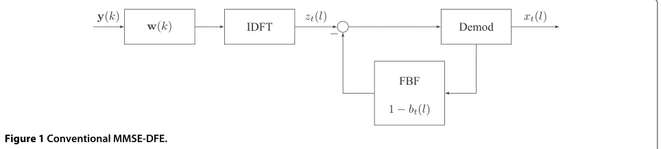
receiver (see Figure 1), the received signal is filtered using a vector-valued feed-forward filter to obtain: z(k) = w(k)y(k). Letz(k) = z(k)−b(k)x(k)is the ISI free sig-nal whereb(k)is the frequency domain FBF. Here, 1 + b(k)=1+Ll=1bt(l)e
−j2πkl
M where the FBF is constrained to have L time domain taps. Note that L is a receiver design parameter and its value can be chosen to be equal to the channel memory. As shown in Figure 1, the FBF is implemented in time domain to obtain a decision variable
zt(l)=zt(l)− L
m=1
bt(m)xt(lm)
ISI
(5)
wherezt(l)is obtained after taking the IDFT ofz(k)and
zt(l)is the ISI free time domain signal which is fed to the
symbol demodulator. Here, the symbol denotes right circular shift operation.
MMSE-DFE filter expressions are given in [21] for the single-receiver antenna case and results for multiple-input-multiple-output (MIMO) systems are available in [31]. In order to obtain an expression for the mean-square error (MSE) which enables closed-form analysis in i.i.d. fading channels, in Appendix 1, we first provide expres-sions for the MMSE-DFE filter for the finite-length case, then we generalize the results for the infinite-length sce-nario. Using these results, for M → ∞, the post-SNR defined as the SNR at the output of an unbiased MMSE-DFE receiver is given by
SNRMMSE-DFE,M→∞=elimM→∞
1
M M−1
k=0 ln
σ2
x||h(k)||2+σ2
n
σ2
n
−1. (6)
3.1 Limiting performance of ZF-DFE in wideband channels
Figure 1Conventional MMSE-DFE.
behavior for the proposed i.i.d. fading channel with infi-nite length. To this end, let
h(k)=
wherevis the effective channel length. We are interested in determining the performance of the link for the limiting case wherev→ ∞. Note that asvtends to∞, sinceM>>
Note that the variablevis replaced withMin (8) line 2 because asv → ∞,M → ∞, sincev << M. Next, we modelht(l)as an i.i.d. zero-mean, complex-Gaussian
vec-tor with covarianceE
ht(l)h†t(l)
= I
v. Note that per-tap
power is set to 1v so that the total power contained in the multi-path channel becomes unity. As v → ∞, we can express the covariance term as: limv→∞Eht(l)h†t(l)
=
limv→∞Iv = limM→∞MI. Again here,vis replaced with M in the limit as v → ∞. We have an infinite num-ber of taps with vanishingly small power. However, the sum total power of all the taps is equal to unity. Using (8), it can be shown thath(k)approaches an i.i.d. com-plex Gaussian vector with zero mean and the covariance tends to an identity matrix, i.e. limv→∞Eh(k)h†(k) → I. More specifically, the probability density function of the elements of the channel vector h(k) approaches an i.i.d. complex Gaussian distribution with zero mean and unit variance, and the vectors h(k) become statistically independent fork=0, 1, ..,M−1.
By settingσn2=0 in the numerator of (6), we obtain the post-SNR of a ZF-DFE as
SNRZF-DFE = σ
Applying the central limit theorem (CLT), the r.v., limM→∞M1 M−1k=0 ln||h(k)||2 approaches Gaussian
dis-The expected logarithm of a chi-square random variable with 2Nr degrees-of-freedom (DOF) is [50]: Eln||h(k)||2 = −β+Nr−1
m=1 m1
where β = 0.577 is the Euler’s constant, and the variance is [50]: Varln||h(k)||2 = ∞
p=1(p+N1r−1). Since the variance term takes a finite value (the series is absolutely con-vergent), the variance of limM→∞M1 M−1k=0 ln||h(k)||2 approaches zero. Therefore, the SNR at the output of the ZF-DFE approaches a constant value of
SNRZF-DFE =
Note that the ZF-LE provides a fixed mean SNR of [45]
SNRZF-LE =
For comparison, post-SNR corresponding to the MFB is given bySNRMFB= Nσ2r
n.
The above result suggests that highly dispersive nature of the frequency-selective channel can be exploited advantageously to obtain a performance comparable to the MFB. After evaluating the expression (13) for the case of a single-receiver antenna, the ZF-DFE provides a post-SNR of 0.5616σ2
n that is 2.5-dB less than the MFB. For this case, both ZF- and MMSE-based LEs perform poorly compared to the MFB [45]. However, the ZF-DFE does not suffer from this limitation and provides a substantial gain over MMSE/ZF-LE. ForNr = 2, the loss of ZF-DFE with
3.2 DFE initialization
In the MMSE-DFE implementation considered in this paper, the feedback filter is implemented in the time domain. In (5), the ISI term Lm=1bt(m)xt(l m) is
obtained by circularly convolving the FBFbt(l) with the
data sequence xt(l). For detecting the first data symbol xt(0), the receiver has to eliminate the ISI caused by the
last L data symbols of the data sequence xt(l).
Specifi-cally, the DFE requires knowledge of the data symbols xi = [xt(N−L), ..,xt(N−2),xt(N−1)]. As proposed
in [28], we use a linear equalizer to obtain hard deci-sions for the required elements contained in xi. These
symbol estimates are then used to initialize the DFE. Simulation shows that this approach works quite well and the loss in the performance compared to the case of an ideal DFE is acceptable. We would like to remark here that an iterative receiver is presented in [23] to address the DFE initialization problem. The results of this paper show that MMSE-LE-based initialization is sufficient to obtain near-ideal performance. An alterna-tive receiver initialization method is also discussed in [31] for trellis-based receivers. Different iterative block DFE methods have been proposed in [23,32] for DFE-precoded-OFDMA systems. These methods use a linear equalizer in the first iteration, then applies block level decision feedback based on soft decisions in subsequent iterations. In this paper, we are mainly concerned with the analysis of conventional DFEs based on hard decision feedback.
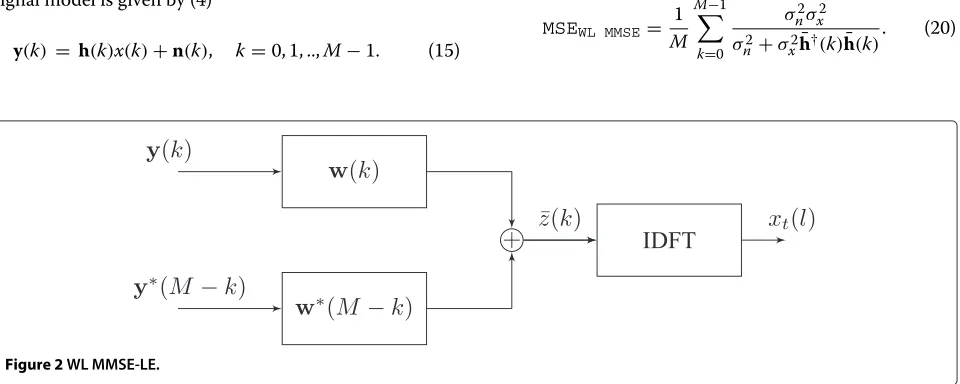
4 Widely linear frequency domain MMSE equalizer
For the special case of real constellations, we consider a frequency domain widely linear equalizer which jointly fil-ters the valued received signal and its complex-conjugated and frequency reversed copy in frequency domain (see Figure 2). Recall that the frequency domain signal model is given by (4)
y(k) = h(k)x(k)+n(k), k=0, 1, ..,M−1. (15)
Applying complex conjugation and frequency reversal operation ony(k), we get
y∗(M−k) = h∗(M−k)x∗(M−k)
+n∗(M−k) (16)
= h∗(M−k)x(k)
+n∗(M−k), k=0, 1, ..,M−1 (17)
where we use the fact thatx∗(M−k)=x(k)for real-valued modulation data. Combining (4) and (17) in vector form, we have
y(k) y∗(M−k)
=
h(k) h∗(M−k)
x(k)+
n(k) n∗(M−k)
.
(18)
We note that two copies of the frequency domain modu-lation signalx(k)are obtained with distinct channel coeffi-cients. Using compact vector notation,y¯(k)= ¯h(k)x(k)+
¯
n(k). The WL filter w¯(k) = [w(k),w∗(M−k)] jointly filters the frequency domain signaly(k), and its complex-conjugated and frequency-reversed copy y∗(M − k) to obtain the scalar decision variable denoted as ¯z(k). Let
¯
z(k) = w(k)y(k) +w∗(M−k)y∗(M−k) = ¯w(k)y¯(k). An estimate of the desired data is obtained as ¯zt(l) =
IDFT[z¯(k)]. Using standard MMSE estimation [18], the vector-valued WL MMSE filter is given by
¯
w(k) = h¯
†(k)
σ2
n σ2
x + ¯h
†(k)h¯(k). (19)
Since w¯(k) = [w(k),w∗(M−k)], where w(k) = h∗(k)
σ2
n
σ2
x+¯
h†(k)h¯(k)
, it is computationally efficient to calculate the
filterw(k)explicitly. The filterw∗(M−k)can be obtained fromw(k)with low computational complexity using com-plex conjugation and frequency reversal operations. The minimum MSE for this case is expressed as
MSEWL MMSE= 1 M
M−1
k=0
σ2 nσx2 σ2
n+σx2h¯†(k)h¯(k)
. (20)
Note that
¯
h†(k)h¯(k) = ||h(k)||2+ ||h(M−k)||2. Using this result, the MSE can be expressed as
MSEWL MMSE=
The post-SNR defined as the SNR at the output of the WL MMSE receiver is given by
SNRWL MMSE= σ
4.1 Liming performance of WL ZF-LE
To obtain a closed-form expression for the post-SNR at the output of the equalizer, we analyze the performance of a ZF WL-LE. Lettingσn2=0 in the denominator ofD, for
For an i.i.d. channel with infinite frequency selectivity, the entries of h(k) are i.i.d. complex Gaussian r.v.’s with zero mean and unit variance. Therefore,||h(k)||2has chi-square distribution. Since ||h(k)||2 always takes positive values, in the limiting case asM→ ∞, the first two terms ofDbecome vanishingly small. Then we end up with
D= lim
The expected value ofDis given by
E[D] = lim
Gaussian r.v’s. The term
1
[||h(k)||2+||h(M−k)||2]
has inverse chi-square distribution with 4Nrreal-valued DOF.
Apply-ing the result of [51], we haveE 1 Nr>1. Therefore, the variance ofDis given by
Var[D] = lim
The post-SNR of WL ZF-LE reaches a constant value of
SNRWL ZF-LE = σ
Note that the variance of
squares of Nr i.i.d. complex Gaussian r.v.’s which give
a chi-square random variable with 2Nr DOF while
||2 is unbounded since it
has inverse chi-square distribution with two DOF. How-ever, the mean of 1
[||h(k)||2+||h(M−k)||2] is bounded for any
value ofNr. In the limiting case asM → ∞, the
contri-bution of the first two terms in (24) vanishes. However, for the special case ofNr = 1, and for finite values ofv,
h(k)andh(M−k)become correlated random variables. Specifically for values ofk = 0 andk = M2, these terms become equal while for values ofkin the vicinity of 0 and
M
2 they become highly correlated. Considering the first
two terms of Equation 24, we see that the terms ||h(10)||2
or 1
||hM2||2 contribute to an increase in the MSE.
Simi-larly, sinceh(k)andh(M−k)can be highly correlated for certain subcarrier locations, the term [||h(k)||2+||1h(M−k)||2]
contributes to an increase in MSE for those subcarrier locations. The overall increase in the MSE can be con-trolled by considering a WL MMSE which regularizes the denominator terms. Simulation is used to quantify the gain of WL MMSE-LE over ZF case.
For detection of real-valued symbols, only the real part of the noise at the output of the equalizer contributes to the error rate. Taking this into account, the post-SNR of a conventional ZF-LE should be modified as
SNRConv ZF-LE, real = 2σ2
x(Nr−1) σ2
n
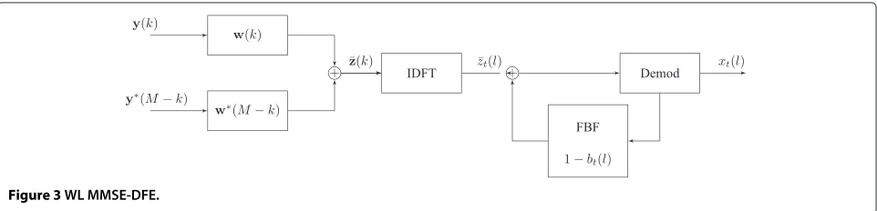
5 WL MMSE-DFE
In the WL MMSE-DFE receiver (see Figure 3), the received signal and its conjugated time-reversed replicas are filtered as
¯
z(k) = ¯w(k)y¯(k)
where w¯(k) = [w(k),w∗(M−k)] is composed of two vector-valued filters. Next, the ISI is eliminated using a feedback filter as
ˆ
z(k)= ¯z(k)− ¯b(k)x(k).
Note thatb¯(k) is the frequency domain feedback filter where 1+ ¯b(k)=1+Ll=1b¯t(l)e
−j2πkl
M . The coefficients of the FBF take real values only. The FBF is implemented in the time domain to obtain a decision variable
ˆ
zt(l)= ¯zt(l)− L
m=1 ¯
bt(m)xt(lm)
ISI
(32)
which is fed to the symbol demodulator. Here, z¯t(l) =
IDFT[¯z(k)] andzˆt(l) = IDFT[ˆz(k)]. In Appendix 2, we
generalize the MMSE-DFE results for the WL case and provide expressions for the FFF, FBF, and the MSE. We note here that the FFF and FBF expressions are distinct from the ones reported in the literature [30]. In addi-tion, the receiver design presented in the Appendix has low implementation complexity. Using the results in the Appendix 2, the post-SNR of the WL MMSE-DFE, for M→ ∞, is given by (60)
SNRWL MMSE-DFE= e
limM→∞M1 M−1
k=0 ln
σ2
x(||h(k)||2+ ||h(M−k)||2)+σ2 n
σ2 n
. (33)
5.1 Performance of WL ZF-DFE in wideband channels Settingσn2=0 in (33), the post-SNR of a WL ZF-DFE can be expressed as
SNRWL ZF-DFE=σ 2 x σ2
n
elimM→∞M1
M−1
k=0 ln
||h(k)||2+ ||h(M−k)||2
.
(34)
Inside the logarithm, we have a sum of squares of 2Nr
i.i.d. complex Gaussian r.v’s. In the limiting case asv →
∞, generalizing the analysis used for the conventional ZF-DFE, we can show that the SNR of WL ZF-DFE reaches a fixed value of
SNRWL ZF-DFE = σ 2 xe
−β+2Nr−1
m=1 m1
σ2 n
. (35)
For real-valued modulation, since only the real part of the noise is relevant, the conventional ZF-DFE provides a fixed SNR of
SNRZF-DFE = 2σ2
xe
−β+Nr−1
m=1 m1
σ2 n
. (36)
ForNr = 1, the ideal WL ZF-DFE offers a post-SNR
of 1.5265σ2
n that is 1.17 dB away from the MFB. The actual performance gap with practical FBF is determined using BER simulation.
5.1.1 Remarks
• For the case of WL ZF/MMSE-DFE, we ignore the potential MSE increase contributed by the terms located atk=0andk= M2. Since at these locations, the exponent in (34) involves the terms
Eln||h(0)||2,E
lnhM22
which take a finite value, the overall increase in the MSE can be neglected for finite values ofM.
• We note here that our main goal of the paper is to expose the basic properties of conventional and WL equalizers in wideband channels. Our aim is not to promote the use of real constellations over typically used complex modulation methods. However, the analysis and results related to WL equalizers are useful in systems where real constellations are employed. One such application is discussed in [52] where binary modulation along with duobinary precoding is employed in the uplink of
DFT-precoded-OFDM to reduce the PAPR.
6 Results
We present BER simulation results for BPSK and 8-PSK and 16-QAM (quadrature amplitude modulation) sys-tems. In all cases, the FBF length is set equal to the channel
memory. Throughout the paper, we present results for a 20-tap i.i.d. Rayleigh fading channel withM = 512 in all cases.
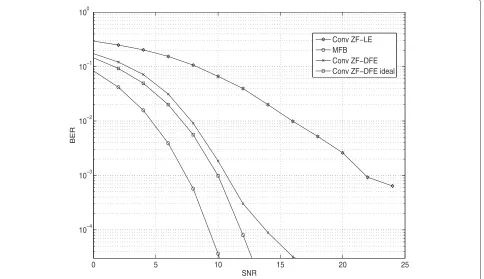
6.1 BER results for conventional equalizers
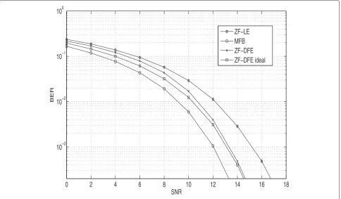
In the following, we consider the BER performance of the single-antenna receivers. In Figure 4, the results are shown for BPSK modulation using ZF receivers. The BER of ideal DFE is close to the conventional DFE up to BER=10−4and shows a degradation at low error rates. This loss is mainly caused by the imperfect initialization of the DFE. Note that the ZF-LE performs poorly due to high noise enhancement. Therefore, initialization of the ZF-DFE with ZE-LE decisions leads to severe error propagation. In Figure 5, BER results are given for 16-QAM system using ZF receivers. The results show that when the ZF-DFE is initialized using known data, the BER follows the ideal DFE case while initialization using the ZF-LE leads to an error floor. In Figure 6, BER is given for 16-QAM employing MMSE-based receivers. Unlike the ZF case, initialization of the MMSE-DFE using MMSE-LE does not cause severe error propagation and the BER is within 2.0 dB of ideal MMSE-DFE. With lower modulation alphabets, like BPSK, the difference between the BER of MMSE-DFE and ideal MMSE-DFE is small (see Figure 7) and the difference increases for higher order constellations. This loss may be reduced using
low-complexity sequence estimation techniques such as RSSE.
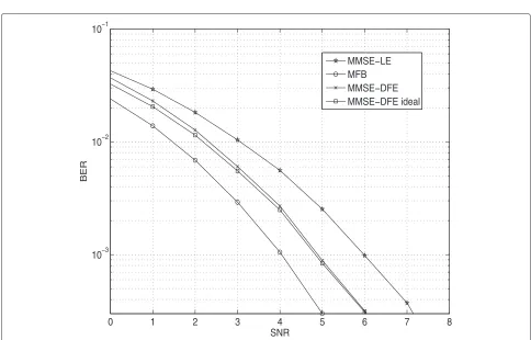
Next, we consider the BER performance of BPSK and 8-PSK system with two antennas (see Figures 8 and 9). We observe that in the presence of multiple-receiver antennas, the BER of LE improves considerably com-pared to the single antenna case. As a result, initial-ization of DFE using the LE does not cause significant degradation.
The theoretical performance gap between the post-SNR of the considered receivers and the MFB is tabulated in Table 1 for an i.i.d. channel with infinite length. In Tables 2 and 3, we report the gap measured at BERs of 0.01 and 0.001, respectively. For ZF-based receivers, the gap mea-sured using simulation is in good agreement with the analytically obtained results.
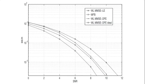
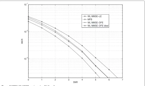
6.2 BER of WL equalizers
In Figure 10, we show the BER for WL MMSE-based receivers employing BPSK modulation for the case of Nr = 1. Comparing with the results of Figure 7, we see
that WL processing provides a gain over conventional receivers. In Figure 11, the results are given for WL ZF receiver withNr = 1. In section 4, it is shown that the
post-SNR of WL ZF-LE approaches(2Nr−1) σ2
n whenv→ ∞. For the case of Nr = 1 and for finite values of v, we
argued that certain SNR penalty is expected. For the single
0 5 10 15 20 25
10−4 10−3 10−2 10−1 100
SNR
BER
Conv ZF−LE MFB Conv ZF−DFE Conv ZF−DFE ideal
0 5 10 15 20 25 10−3
10−2 10−1 100
SNR
BER
ZF−LE MFB
ZF−DFE initialization using LE decisions ZF−DFE ideal DFE
ZF−DFE initialization with known data
Figure 516-QAM, conventional ZF receivers,L=20, Nr=1.
0 5 10 15 20 25
10−6 10−5 10−4 10−3 10−2 10−1 100
SNR
BER
MMSE−LE MFB MMSE−DFE MMSE−DFE ideal
0 2 4 6 8 10 12 14 10−3
10−2 10−1 100
SNR
BER
Conv MMSE−LE MFB
Conv MMSE−DFE MMSE−DFE ideal
Figure 7BPSK, conventional MMSE receivers,L=20, Nr=1.
0 1 2 3 4 5 6 7 8
10−3 10−2 10−1
SNR
BER
MMSE−LE MFB MMSE−DFE MMSE−DFE ideal
0 2 4 6 8 10 12 14 16 18 10−3
10−2 10−1 100
SNR
BER
ZF−LE MFB ZF−DFE ZF−DFE ideal
Figure 98-PSK, conventional ZF receivers,L=20, Nr=2.
antenna case, while we expect a 3.0-dB SNR gap between the post-SNR of WL ZF-LE and MFB, Tables 2 and 3 show a gap of 3.2 and 3.8 dB, respectively. However, for the dual antenna case, the gap reported in Tables 2 and 3 is in good agreement with the analytically obtained results given in Table 1.
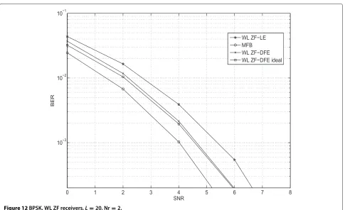
Referring to Figures 10 and 11, we note that the SNR difference between ideal DFE and actual DFE with LE-based initialization is approximately 0.4 dB for both ZF and MMSE cases for Nr = 1. In Figures 12 and 13,
results are given for the case of Nr = 2. We see
that the performance of actual DFE is very close to that of the ideal DFE. The additional DOF obtained by WL processing aid the WL DFEs to mitigate the error propagation.
Table 1 Theoretically expected SNR gap of the receiver with respect to the MFB in decibels (dB)
Receiver type Gap forNr=1 Gap forNr=2
Conv ZF-LE NA 3.0
Conv ZF-DFE 2.5 1.19
WL ZF-LE 3.0 1.25
WL ZF-DFE 1.17 0.5644
7 Conclusions
This paper describes the limiting behavior of conven-tional and WL equalizers in wideband frequency-selective channels. For systems employing DFT-precoded-OFDM modulation, closed-form expressions are obtained for the post-SNR of conventional and WL receivers employing ZF-LE and ZF-DFE; simulation is used to assess the per-formance of MMSE-based receivers. In i.i.d. fading chan-nels with infinite channel memory, the post-SNR reaches a fixed value that is comparable to the MFB in most cases.
Table 2 SNR gap of the receiver with respect to MFB in decibels (dB) at BER = 0.01 for BPSK
Receiver type Gap forNr=1 Gap forNr=2
Conv ZF-LE NA 3.0
Conv ZF-DFE 2.5 1.2
Conv MMSE-LE 3.4 1.65
Conv MMSE-DFE 1.4 0.75
WL ZF-LE 3.2 1.3
WL ZF-DFE 1.2 0.6
WL MMSE-LE 2.15 1.0
Table 3 SNR gap of the receiver with respect to MFB in decibels (dB) at BER = 0.001 for BPSK
Receiver type Gap forNr=1 Gap forNr=2
Conv ZF-LE NA 3.2
Conv ZF-DFE 2.6 1.1
Conv MMSE-LE 4.2 2.0
Conv MMSE-DFE 1.7 0.8
WL ZF-LE 3.8 1.4
WL ZF-DFE 1.17 0.6
WL MMSE-LE 2.55 1.0
WL MMSE-DFE 1.05 0.5
Both conventional MMSE-LE and ZF-LE offer near optimal performance only when the receiver has multi-ple antennas, whereas ideal ZF-DFE and ideal MMSE-DFE perform close to the MFB with a fixed SNR penalty even when the receiver has a single antenna. For single-antenna MMSE-DFE with decision feedback, the penalty compared to the ideal DFE is approximately 2.0 dB for 16-QAM systems at high SNRs. The total gap compared to MFB is 4.5 dB. Low-complexity receiver algorithms that further reduce this gap need to be devel-oped. Unlike the single antenna case, the presence of
multiple antennas helps the DFEs to reach a perfor-mance close to the MFB. Multiple-receiver antennas are also shown to reduce the error propagation of the DFEs.
For single-antenna systems employing real-valued mod-ulation alphabets, WL receiver processing can be used to obtain a performance advantage over conventional receivers. In particular, the WL MMSE-LE performs within 3.2 to 3.8 dB of the MFB while the WL MMSE-DFE reduces the gap with respect to the MFB to 1.0 dB. Results show that the multi-antenna WL receivers (both LEs and DFEs) perform very close to the MFB as predicted by the infinite length i.i.d. fading channel model.
We note here that the proposed infinite length i.i.d fad-ing channel model can be used to obtain the limitfad-ing performance of MIMO systems employing spatial multi-plexing (SM). The analysis has been carried out in [53] for the case of MIMO ZF-LE where it is shown that the post-SNR of the receiver reaches a constant value ofNr−Nt
σ2
n for Nr > Nt, whereNtis the SM rate. Extension to the
gen-eral case of SM employing ZF/MMSE-DFEs is yet to be considered.
Endnote
a(A+BCD)−1=A−1+A−1BC−1+DA−1B−1DA−1
0 2 4 6 8 10 12
10−3 10−2 10−1 100
SNR
BER
WL MMSE−LE MFB
WL MMSE−DFE WL MMSE−DFE ideal
0
2
4
6
8
10
12
14
10
−310
−210
−110
0SNR
BER
WL ZF−LE
MFB
WL ZF−DFE
WL ZF−DFE ideal
Figure 11BPSK, WL ZF receivers,L=20, Nr=1.
0 1 2 3 4 5 6 7 8
10−3 10−2 10−1
SNR
BER
WL ZF−LE MFB WL ZF−DFE WL ZF−DFE ideal
0 1 2 3 4 5 6 7 10−3
10−2 10−1
SNR
BER
WL MMSE−LE MFB
WL MMSE−DFE WL MMSE−DFE ideal
Figure 13BPSK, WL MMSE receivers,L=20, Nr=2.
Appendices Appendix 1
Derivation of MMSE-DFE filter settings
We obtain closed-form expressions for the FFF, FBF and MSE for the case when the FBF is restricted to have finite length. First, we show that the MSE minimizing solution for the FBF becomes a finite length prediction error fil-ter that whitens the error covariance at the output of the MMSE-LE. The solution obtained in our case becomes a multiple-receiver antenna generalization of the results presented in [21]. Similarly, Gerstacker et al. [31] pre-sented an alternative approach for MIMO systems where the problem of designing the FBF is formulated as one of finite length prediction error filter design. This alterna-tive approach results in a solution that agrees with our results for the multiple-receiver antenna case. We fur-ther generalize our results to the infinite length filter case which facilitates performance analysis in i.i.d. fading chan-nels. The derivations presented in this section follow the approach presented in [13,18]. We define an error signal
e(k)= z(k)−x(k). (37)
This is written in time domain as
et(l)=zt(l)−xt(l)− L
m=1
bt(m)xt(lm). (38)
Define:ree(k) =E
||e(k)||2. Using Parseval’s theorem: 1
M M−1
k=0 ||e(k)||2 = M−1l=0 ||et(l)||2. Taking expectation
on both sides, we get
1 M
M−1
k=0
ree(k)= M
l=0
E||et(l)||2
.
The MSE is defined as MSE = E||et(l)||2
which is independent of the time indexl. It can be written as
MSE= 1 M2
M−1
k=0 ree(k).
Next, we obtain an expression for the FFF in frequency domain. Applying orthogonality principle [18]
E
e(k)y†(k)
=0, for k=0, 1, ..,M−1. (39)
Substituting (37), in (39), and evaluating the expecta-tion, the FFF can be expressed as
w(k) = (1+b(k))Rxy(k)R−1yy(k) (40)
where Rxy(k) = E
x(k)y†(k) = rxx(k)h†(k) and
Ryy(k) = E
y(k)y†(k) = h(k)rxx(k)h†(k)+Rnn(k)
. Here rxx(k) = E
Note that (43) follows from applying matrix inversion lemmaa. With this choice of FFF, the minimum MSE can be shown to be [13,18]
MSE= 1
To obtain the coefficients bt(l), we take the partial
derivatives
Treating bt(l) and b∗t(l) as independent variables,
we get ∂b∂t(l)
. Substituting this result in (45) and setting the partial derivatives to zero, we obtain the MSE minimizing condition
We define the following IDFT pair
q(l)= 1
is the frequency domain error
covariance at the output of a MMSE-LE [18] whereq(l) is the corresponding time domain error covariance. Now, we can express (46) in compact form as
Ab∗= −q∗ (48)
where the (l,m)th element of the matrixA is given by A(l,m) = q(m − l), b = [bt(1),bt(2), ..,bt(L)]Tr, and
q = q(1),q(2), ..,q(L+1)Tr. The elements of the FBF can be obtained by solving (48). It can be seen that the MSE minimizing solution for the FBF becomes a finite length prediction error filter of orderLthat whitens the error covariance at the output of the MMSE-LE. The FBF coefficients can be calculated efficiently using the Levinson-Durbin recursion. The minimum MSE can be obtained by substituting the values of the FBF coeffi-cients in the MSE expression (44). Next, we characterize the MMSE-DFE for the case ofM→ ∞.
Expanding the log spectrum using the DFT
ln
. In the limiting case asM→ ∞, the DFTs approach discrete-time Fourier transforms (DTFTs) i.e.,
where
The result on line 2 is obtained by expanding the expo-nential function into an infinite series. The coefficients gt(l)are obtained by collecting appropriate terms in the
summation on line 2. Note thatg(f)is a causal, monic, and minimum-phase filter with all its poles and zeros inside the unit circle. Similarly,g∗(f)is a non-causal, monic, and maximum phase filter. ForM→ ∞, (50) can be written as
is a periodic inf with period 1. Further,
γ = elimM→∞
Now, we write the spectrum factorization for the con-tinuous case as [13,18]
The MSE given by (44) becomes
MSE = lim
The optimum choice which minimizes the MSE given in (53) is given by 1+b(f) = g(f)[13,18]. Using this, and
substituting (51) in the MSE expression (53), we obtain the minimum MSE as
MSEM→∞ = σ 2 n γ .
Assuming ideal decision feedback, the SNR at the output of the MMSE-DFE is given by
SNRMMSE-DFE = σ
Derivation of WL MMSE-DFE filter settings
In this section, we discuss the design aspects of WL MMSE DFE. The key implementation differences between conventional and WL equalizers are highlighted. Specif-ically, we notice that the noise covariance term at the output of the WL MMSE section exhibits even symme-try in frequency domain. This property is exploited to reduce the computational complexity of FFF and FBF filter calculation.
The error signal for WL case is defined as
¯
total MSE is given by
MSEWL DFE=
Following the conventional MMSE-DFE case, the MSE minimizing solution for the WL FFF can be obtained as
The minimum MSE can be expressed as
Consider the partial derivatives
∂MSEWL DFE
Substituting this result in (54) and setting the partial derivatives to zero, we get
1
Let us define the following transform pair
¯
It can be implemented with low complexity using stan-dard inverse fast Fourier transform (IFFT) algorithm. Alternatively, noting thatP(k)= P(M−k), we can write
The last term involves M2 point type-1 DCT of P(k). Note thatq(l)¯ needs to be calculated only for the first M2 terms since the rest of the coefficients can be obtained exploiting the even symmetry ofq¯(l)i.e.,q¯(l)= ¯q(M−l). The MSE minimizing condition (55) can be expressed in vector-matrix form as
Note that FBF can be calculated with low complexity using Levinson-Durbin recursion which involves real-valued quantities whereas the FBF for the conventional case involves complex values. Now we consider the infinite length filter case.
Following the derivations for the conventional case, we can show that
MSEWL MMSE-DFE= lim
M→∞
The authors declare that they have no competing interests.
Acknowledgements
This work was carried out as part of Converged Cloud Communication Technologies project sponsored by the Department of Electronics and Information Technology (DeitY), Government of India.
Received: 13 March 2014 Accepted: 26 August 2014 Published: 3 October 2014
References
1. 3GPP, 3GPP TS 36.211 V8.2.0 (2008-03). [Online]. Available http://www.3gpp.org
2. C Ciochina, D Mottier, H Sari, An analysis of three multiple access techniques for the uplink of future cellular mobile systems. European Trans. TeleCommun.19(2008)
3. 3GPP, Physical Layer Aspects for Evolved UTRA (Release 8), 3GPP Std, TS 36.211 (2008)
4. X Ma, W Zhang, Fundamental limits of linear equalizers: diversity, capacity, and complexity. IEEE Trans. Inform. Theory.54, 3442–3456 (2008) 5. C Tepedelenlioglu, Maximum multipath diversity with linear equalization
in precoded OFDM systems. IEEE Trans. Inform. Theory.50, 232–235 (2004) 6. A Hedayat, A Nosratinia, N Al-Dhahir, inSignals, Systems and Computers
(ASILOMAR), 2004. Outage probability and diversity order of linear equalizers in frequency-selective fading channels, (2004) 7. SP Shenoy, I Ghauri, DT Slock, inIEEE International Workshop Signal
8. S Song, KB Letaief, Diversity analysis for linear equalizers over ISI channels. IEEE Trans. Commun.59, 2414–2423 (2004)
9. Z Wang, X Ma, G Giannakis, OFDM or single-carrier block transmissions? IEEE Trans. Commun.52, 380–394 (2004)
10. J Cioffi, G Dudevoir, MV Eyuboglu, GD Forney, MMSE decision-feedback equalizers and coding-part 1: equalization results. IEEE Trans. Commun. 43, 2582–2594 (1995)
11. MMSE decision-feedback equalizers and coding-par 2: coding results. IEEE Trans. Commun.43, 2595–2603 (1995)
12. A Medles, DT Slock, inProceedings on the ISIT 2004. Decision-feedback equalization achieves full diversity for finite delay spread channels, (2004) 13. N Al-Dhahir, MMSE decision-feedback equalizers: finite length results.
IEEE Trans. Commun.41, 961–975 (1995)
14. MY Eyuboglu, S Quereshi, Reduced state sequence estimation with setpartitioning and decision feedback. IEEE Trans. Commun.36, 13–20 (1988)
15. GD Forney, Maximum-likelihood sequence estimation of digital sequences in the presence of intersymbol interference. IEEE Trans. Inform. Theory.18, 363–378 (1972)
16. G Ungerboeck, Adaptive maximum-likelihood receiver for carrier-modulated data-transmission systems. IEEE Trans. Commun. 22, 624–636 (1974)
17. WH Gerstacker, R Schober, Equalization concepts for EDGE. IEEE Trans. Wireless Commun.1, 190–199 (2002)
18. J Cioffi,EE:379 Stanford Class Notes. [Online]. Available: http://www.stanford.edu/class/ee379a/
19. SL Ariyavisitakul, JH Winters, I Lee, Optimum space-time processors with dispersive interference: unified analysis and required filter span. IEEE Trans. Commun.47, 1073–1083 (1999)
20. RFH Fischer,Precoding and Signal Shaping for Digital Transmission. (Wiley) 21. N Benvenuto, S Tomasin, On the comparison between OFDM and single carrier modulation with a DFE using a frequency-domain feedforward filter. IEEE Trans. Commun.50, 947–55 (2002)
22. D Falconer, S Ariyavisitakul, A Benyamin-Seeyar, B Eidson. in IEEE Commun. Mag. (2002)
23. N Benvenuto, S Tomasin, Iterative design and detection of a DFE in the frequency domain. IEEE Trans. Commun. (2005)
24. R Dinis, D Falconer, Iterative block decision feedback equalization techniques (IB-DFE) for broadband wireless systems
25. R Dinis, A Gusmão, N Esteves, On broadband block transmission over strongly frequency-selective fading channels
26. Iterative block-dfe techniques for single-carrier-based broadband communications with transmit/receive space diversity
27. R Dinis, P Carvalho, L Bernardo, R Oliveira, M Pereira, P Pinto, Frequency domain multipacket detection: a high throughput technique for SC-FDE system. IEEE Trans. Wireless Commun. (2005)
28. M Padmanabhan, R Vinod, K Kuchi, K Giridhar, inNational Conference on Communications. MMSE DFE for MIMO DFT-spread OFDMA (Guwahati, India, 2009)
29. N Prasad, S Wang, X Wang, Efficient receiver algorithms for DFT-spread OFDM systems. IEEE Trans. Wireless Commun. (2009)
30. Z Lin, P Xiao, V Vucetic, Analysis of receiver algorithms for LTE SC-FDMA based uplink MIMO systems. IEEE Trans. Wireless Commun. (2010) 31. W Gerstacker, P Nickel, F Obernosterer, UL Dang, P Gunreben, W Koch, in
Proceedings of the International Conference on Communications. Trellis-based receivers for SC-FDMA transmission over MIMO ISI channels, (2008), pp. 4526–4531
32. A Silva, J Assunção, R Dinis, A Gameiro, Performance evaluation of IB-DFE-based strategies for SC-FDMA systems. EURASIP J. Wireless Commun. Netw. [Online]. Available: http://jwcn.eurasipjournals.com/ content/2013/1/292
33. B Picinbono, P Chevalier, Widely linear estimation with complex data. IEEE Trans. Signal Process.43, 2030–2033 (1995)
34. YC Yoon, H Leib, Maximizing SNR in improper complex noise and application to CDMA. IEEE Commun. Lett.1, 5–8 (1997) 35. G Gelli, L Paura, A Ragozini, Widely linear multiuser detection. IEEE
Commun. Lett.4, 187–189 (2000)
36. S Buzzi, M Loops, A Tulino, inISIT. A new class of multiuser CDMA receivers based on minimum mean-output-energy strategy, (2000)
37. A Lampe, M Breiling, inProceedings of the Information Theory Workshop. Asymptotic analysis of widely linear MMSE multiuser detection-complex vs real modulation, (2001), pp. 55–57
38. A Lampe, R Schober, WH Gerstacker, J Huber, A novel iterative multiuser detector for complex modulation schemes. IEEE J. Select. Areas Commun. 20, 339–350 (2002)
39. WH Gerstacker, R Schober, A Lampe, Receivers with widely linear processing for frequency-selective channels. IEEE Trans. Commun. 51, 1512–1522 (2003)
40. WH Gerstacker, F Obernosterer, R Schober, A Lehmann, A Lampe, P Gunerben, Equalization concepts for Alamouti space-time block code. IEEE Trans. Commun.52, 1178–1190 (2004)
41. D Darsena, G Gelli, L Paura, F Verde, Widely linear equalization and blind channel identification for interference-contaminated multicarrier systems. IEEE Trans. Signal Process.53, 1163–1177 (2005) 42. D Darsena, G Gelli, L Paura, F Verde, Subspace-based blind channel
identification of SISO-FIR systems with improper random inputs. in EURASIP J. Signal Process (2004)
43. P Chevalier, F Pipon, New insights into optimal widely linear array receivers for demodulation of BPSK, MSK, and GMSK corrupted by noncircular interferers-application to SAIC. IEEE Trans. Signal Process. 54, 870–883 (2006)
44. H Trigui, D Slock, inProceedings of the International Conference on Universal Personal Communications. Cochannel interference cancellation within the current GSM standard, (1998), pp. 511–515
45. K Kuchi, Limiting behavior of ZF/MMSE linear equalizers in wideband channels with frequency selective fading. IEEE Commun. Lett. 16, 929–932 (2012)
46. D Darsena, G Gelli, L Paura, F Verde, Blind channel shortening for asynchronous SC-IFDMA systems with CFOs. IEEE Trans. Commun. (2013) 47. D Darsena, G Gelli, F Verde, Joint blind channel shortening and
compensation of transmitter I/Q imbalances and CFOs for uplink SC-IFDMA systems. Elsevier Physical Communication (2014) 48. F Verde, inEurasip Journal on Applied Signal Processing. Frequency-shift
zero-forcing time-varying equalization for doubly selective SIMO channels, (2006)
49. , inTenth International Symposium on Wireless Communication Systems (ISWCS). Low-complexity time-varying frequency-shift equalization for doubly selective channels (Ilmenau, Germany, 2013)
50. O Oyman, R Nabar, H Bolcskei, A Paulraj, Characterizing the statistical properties of mutual information in MIMO channels. IEEE Trans. Signal Process.51, 2784–95 (2003)
51. J Bernardo, A Smith,Bayesian Theory. (Wiley, 1993)
52. K Kuchi, Partial response DFT-precoded-OFDM modulation. Trans. Emerg. Telecommunications Technol. (2012)
53. MMSE-prewhitened-MLD equalizer for MIMO DFT-precoded-OFDMA. IEEE Wireless Commun. Lett.1, 328–331 (2012)
doi:10.1186/1687-1499-2014-159
Cite this article as:Kuchi:Performance limits of conventional and widely linear DFT-precoded-OFDM receivers in wideband frequency-selective channels.EURASIP Journal on Wireless Communications and Networking