6
Improving Performance and Reliability of Transmission
Line using UPFC
Foram Thaker
1, Vatsal Patel
2Department of Electrical Engineering, School of Engineering, R. K. University
Email: [email protected]1
Abstract- Growing needs of electrical energy, deregulation of market, constraints in capacity building have forced electric utility to make optimum use of the available resources and consistently deliver quality power. Advancement in technologies has made it possible to have improvised performance of existing infrastructure through devices like Flexible AC transmission systems (FACTS). In this paper a segment of transmission network of Rajkot city has been taken as a case study and how use of FACTS devices like UPFC helps to improve or control the power flow in the network under some of the hypothetical load conditions based on probable future scenario is studied. Transmission network model has been prepared in Simulink MATLAB on basis of the data collected Gujarat Electricity Transmission Corporation Ltd. (GETCO). Power flow in the network is studied under assumed load conditions both with and without using UPFC and results are compared.
Index Terms- FACTS, UPFC, Power systems.
1. INTRODUCTION
Electricity is a highly engineered product, however the ongoing expansion and growth of electric utility industry and introduction of deregulation in many countries have brought numerous changes in the domain. Electricity is now slowly looked upon and handled as a commodity. This evolving utility environment and market forces are forcing for more optimal and profitable operations of power system and this trend will continue and gain more importance in coming days. Further, to meet the growing market needs upgrading transmission system infrastructure in term of new transmission lines, substations and associated equipments does not always prove to the possible solution. In fact this proves to be time consuming, expensive and many a times controversial too. In regards to all these, more efficient utilization and control of existing transmission system infrastructure has become essential and inevitable. Effectively operating transmission system close to their stable and thermal limits with focus on delivery of quality power has become norm of the day.
Today, advance control technologies have made it possible to achieve improved utilization of existing power system. Flexible AC transmission systems (FACTS), that are power electronics based equipments, presents one of the possible solutions to new challenges in transmission system. FACTS allow efficient operation of transmission system with minimal infrastructure investment, implementation time and other environmental impacts compared to construction of new transmission lines [1, 2].
This paper briefly introduces the concept of FACTS and various types of FACTS devices and demonstrates the use of UPFC for controlled and improved power flow over a segment of actual transmission network of Rajkot city under hypothetical load condition based on future scenario. The paper is organized as follows. In Section 2, FACTS and its types are introduced with emphasis on FACTS under study, i.e. Unified power flow controller (UPFC). This is followed by discussion on the model of transmission network of Rajkot city, taken as case study, prepared on basis of the data collected form Gujarat Electricity Transmission Corporation Ltd. (GETCO) in Section 3. In Section 4 various hypothetical load conditions are taken and how UPFC can efficiently help in handling such load conditions is illustrated through simulations. This is followed by conclusion in Section 5. Transmission network model and all simulations have been done using SimPowerSystem of Simulink, MATLAB.
2. REVIEW OF FACTS AND UPFC
7 transient stability, etc. FACTS controller can be
classified as follows [1].
(1)Series connected controllers: Thyristor controlled series capacitor or compensator (TCSC), Static synchronous series compensator (SSSC) (series connected)
(2)Shunt connected controllers: Static VAR compensator (SVC), Static synchronous compensator (STATCOM)
(3)Combined series-series controllers: Interline power flow controller (IPFC)
(4)Combined shunt-series controllers: Thyristor Controlled Phase Shifting Transformer (TCPST), Unified power flow controller (UPFC).
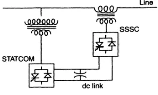
UPFC is one of the most versatile FACTS devices. As shown in Figure 1, it combines STATCOM and SSSC and gives complete control of active and reactive power as well as line voltage control. As shown in Figure 2 it comprises of two Voltage source converters (VSC) coupled through a common DC terminal. Convert 1 is connected in shunt with the line through a coupling transformer and converter 2 is inserted in series with the transmission line through an interface transformer. The DC voltage for both converters is provided by a common capacitor bank. The series converter is controlled to inject a voltage phasor, Vpq, in series with the line, which can be varied from 0 to Vpq max. Moreover, the phase angle of Vpq can be independently varied from 0 to 360 degrees. In this process, the series converter exchanges both real and reactive power with the transmission line. Although the reactive power is internally generated/ absorbed by the series converter, the real-power generation/ absorption is made feasible by the dc-energy–storage device—that is, the capacitor. The shunt-connected converter 1 is used mainly to supply the real-power demand of converter
a STATCOM and independently regulate the terminal voltage of the interconnected bus by generating/ absorbing a requisite amount of reactive power [2].
Literature is available discussing different approaches for installing UPFC in power system. The concept and characteristics have been discussed in detail in [3]. Number of literature represents use of UPFC in power flow control [4-6], in improving power quality [7, 8] and power system stability [9, 10]. Literature is also available discussing various models of UPFC [11, 12] and algorithms for optimum placement of UPFC [13, 14].
Fig. 2 Basic circuit arrangement of UPFC.
3. TRANSMISSION NETWORK MODEL UNDER STUDY
[image:2.595.318.474.70.164.2] [image:2.595.307.537.409.535.2]Fig. 3. Topology of transmission network under study.
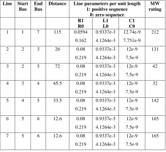
Table 1: Line data of the network under study.
Line Start Bus
End Bus
Distance Line parameters per unit length 1: positive sequence
0: zero sequence
MW rating
R1 R0
L1 L0
C1 C0 1 1 7 115 0.0594
0.162
0.9337e-3 4.1264e-3
12.74e-9 7.751e-9
212
2 2 3 26 0.08
0.219
0.9337e-3 4.1264e-3
12e-9 7.5e-9
131
3 2 5 72 0.08
0.219
0.9337e-3 4.1264e-3
12e-9 7.5e-9
42
4 3 4 45.5 0.08
0.219
0.9337e-3 4.1264e-3
12e-9 7.5e-9
32
5 4 5 33.5 0.08
0.219
0.9337e-3 4.1264e-3
12e-9 7.5e-9
142
6 5 6 12.6 0.08
0.219
0.9337e-3 4.1264e-3
12e-9 7.5e-9
165
7 5 6 12.6 0.08
0.219
0.9337e-3 4.1264e-3
12e-9 7.5e-9
[image:3.595.129.468.355.666.2]
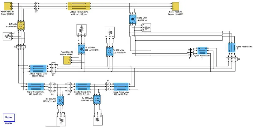
Fig. 4. Simulink model of the network under study. Table 2: Bus data of the network under study.
Bus Bus Voltage
(kV)
Generation (MW)
Load (MW)
1 400 800 0
2 220 0 800
3 220 0 160
4 220 0 240
5 220 70 340
6 220 0 600
7 400 1100 0
The model represents a seven bus system with two buses of 400 kV and others of 220 kV. Present study is focused on power flow control on double circuit line i.e. L6 and L7 between bus B5 and B6. Study of current loading pattern in the network shows that these 220 kV double circuit line is the key source in supplying power to Rajkot city. Some of the major highlights of these lines are as follow.
• Each of these 220 kV double circuit line imports average load of 160-170 MW from B6.
• Bus B5 is also connected to a generator of capacity 35 MW of wind energy type.
• Bus B5 has a major export of around 120-130 MW to B4 and it is also connected over 220 kV line to B2.
• Nine 66 kV lines goes to various substations from bus B5 which are considered here as a load.
The present study and implementation of UPFC for power flow control is based on following hypothesis on this network.
Currently lines L6 and L7 are at operating at nearly 60-70% of their full load capacity. In case when one of the lines is under tripping or is switched off, it is proposed to be studied that how UPFC can help to automatically control the power flow in other line at its best efficient performance and preventing it from tripping due to overload condition. Further, it has to be studied if the over load condition on line L6 and L7 can be eased by regulating the power flow on line L3 between buses B5 and B2.
4. AIMPLEMENTATION OF UPFC AND SIMULATION RESULTS
Fig. 5. Network line L7 switched off without UPFC .
Fig. 6.Network with line L7 switched off with UPFC implemented
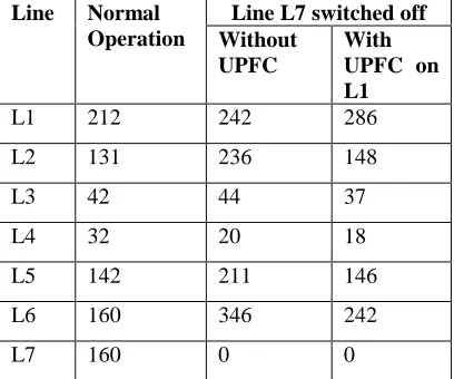
Table 3: Simulation results under various operating conditions
Line Normal Operation
Line L7 switched off Without
UPFC
With UPFC on L1
L1 212 242 286
L2 131 236 148
L3 42 44 37
L4 32 20 18
L5 142 211 146
L6 160 346 242
L7 160 0 0
5. CONCLUSION
[image:5.595.80.284.558.728.2]In Transmission Lines using Simulikmodel With UPFC, International Conference on Computing, Electronics and Electrical Technologies.
[5] Zhengyu Huang, Yixin Ni, C. M. Shen, Felix F. Wu, Shousun Chen, and Baolin Zhang, (2000), Application of Unified Power Flow Controller in Interconnected Power Systems—Modeling, Interface, Control Strategy, and Case Study, IEEE Transactions On Power Systems, Vol. 15, No. 2, pp. 817-823.
[6] H. Chengaiah, R.V.S. Satyanarayana & G.V. Marutheswar,(2012), Study on Effect of UPFC Device in Electrical Transmission System: Power Flow Assessment, International Journal of Electrical and Electronics Engineering (IJEEE), Vol 1, No.4, pp. 66-70.
[7] P.Kannan and S. Chenthur Pandian, (2011), Case Study on Power Quality Improvement of Thirty Bus System with UPFC, International Journal of Computer and Electrical Engineering, Vol. 3, No. 3, pp. 417-420
[8] Arup Ratan Bhowmik, Champa Nandi, (2011) Implementation of Unified Power Flow Controller (UPFC) for Power Quality Improvement in IEEE 14-Bus System International Journal on Comp. Tech. Appl., Vol 2, No. 6, pp. 1889-1896.
[9] Gholipour E., (2005), Improving of transient stability of power systems using UPFC, IEEE Transactions on Power delivery, Vol 20, No 2, 1677-1682.
[10]Ashiwin kumar Sahoo, (2010) An improved UPFC control to enhance power system stability, Modern applied science, Vol 4, No. 6, pp 37-48. [11]Keri A. J. F,(1999), Unified power flow
controller: modeling and analysis, IEEE Transactions on Power delivery, Vol 14, No 2, pp. 648-654.
[12]A.M.Vural and M.Tumay (2003), Steady State Analysis of Unified Power Flow Controller; Mathematical Modelling and Simulation Studies, IEEE Bologna Power Tech Conference, pp.23-26.